
 Submit a Paper
 Propose a Special lssue
 Open Access
ARTICLE
Investigation on the Long Term Operational Stability of Underground Energy Storage in Salt Rock
1 Petroleum Engineering School, Southwest Petroleum University, Chengdu, China
2 Oil & Gas Sales Center of Sinopec Southwest Oil & Gas Company, Chengdu, China
* Corresponding Authors: Jun Zhou. Email: ; Guangchuan Liang. Email:
Energy Engineering 2023, 120(1), 221-243. https://doi.org/10.32604/ee.2022.020317
Received 16 November 2021; Accepted 21 April 2022; Issue published 27 October 2022
 View Full Text
 Download PDF
Abstract
Underground energy storage is an important function of all energy supply systems, and especially concerning the seemingly eternal imbalance between production and demand. Salt rock underground energy storage, for one, is widely applied in both traditional and renewable energy fields; and this particular technique can be used to store natural gas, hydrogen, and compressed air. However, resource diversification and structural complexity make the supply system increasingly uncertain with the passing years, leading to great challenges for energy storage facilities in the present, and perhaps going into the future as well. Hence, it is necessary to research the operation stability of underground energy storage further. In this paper, a stability evaluation index system of Underground Gas Storage (UGS) is constructed with natural gas as the main medium, according to FLAC 3D cavity creep simulation software, along with fuzzy membership function to comprehensively determine the impact factor scoring model; the subjective weight is calculated based on the improved Analytic Hierarchy Process (AHP), the objective weight is calculated by the Entropy Weight Method (EWM), the combined constant weight is obtained by combining the variance maximization theory, and introducing the variable weight theory to obtain a more accurate combined variable weight. Finally, with this all being considered and accounted for, and with the four different conditions designed for UGS deployment case analysis and verification taken into consideration, the combined variable weight evaluation achieved excellent results; compared with the traditional constant weight method, in fact, the new evaluation results are more rigorous and objective.Keywords
Natural gas, as a clean, cheap, and high-valuable natural fuel, plays an irreplaceable role in the daily life of residents nearly everywhere across the world. With the gradual increase in global energy consumption, it is more and more critical to increase strategic energy reserves accordingly and proportionately [1]. Due to its very low permeability, good creep effect, and self-healing properties, salt rock is, therefore, widely used as an energy storage medium. Regarding China in particular, those local salt mines have complex geological conditions, many layers, a single thin layer, and many insoluble interlayers in the deposit, such as anhydrite, glauberite, and mudstone. Hysteresis dissolution will cause turbulence in the flow field in the cavity, and the shape of the cavity in this instance is quite difficult to control. If the shape is out of control, the cavity will be scrapped entirely [2]. At present, there are 80 large-scale salt cavern UGS globally, which have been in operation for nearly 50 years. Operating experience has shown that the stability of the gas storage cavity has become among the biggest keys to safe operation. The long-term stability evaluation of the salt rock UGS during the operation period requires, then, a more rigorous and comprehensive evaluation method to make the results of such studies more objective and credible, to better understand the actual operation status of the salt rock UGS, and to allow for the creation of better, more targeted recommendations and practical suggestions regarding the construction and operation management of salt cavern UGS in general.
According to the literature survey, it is found that the academic community has previously carried out a lot of research on the stability of salt cavern UGS. This research has mainly focused on the mechanical properties and creep properties of salt rock, and it has often analyzed the stability conditions of salt cavern UGS in a specific operating period using field experiments and numerical simulation.
The Federal Republic of Germany and the Democratic Republic of Germany started early. Their research results show that the underground caverns with a depth of 650--800 m can operate safely and economically at an internal pressure of 10–24 MPa. Menzel et al. [3] researched the size, shape, and buried depth of caverns in salt rock UGS, made corresponding recommendations, and provided safe storage pressures too. Wang et al. [4] used FLAC 3D to establish a finite element model regarding salt cavern UGS, and discussed the impact of pillar width, internal pressure, buried depth, creep time, and pressure difference in adjacent salt caverns on gas storage. Wang et al. [5] proposed a quantitative evaluation safety index system consisting of displacement, volumetric shrinkage, plastic zone, expansion safety factor, and equivalent strain. Yin et al. [6] proposed the Micro Leakage Intermediate Layer (MLI), established a three-dimensional geological model of adjacent caverns, and performed numerical simulations under different working conditions, optimizing flexibility for UGS field operations in the process. Yan et al. [7] aimed at the current situation where data is concentrated on the worst category and cannot correctly represent the importance of pollutants; the traditional Entropy weight method, (EWM) is improved based on the relative entropy theory, enhancing the rationality of weighting results. Tunsakul et al. [8] evaluated the stability and rock fracture patterns based on the element-free Galerkin method for a highly pressurized gas storage cavern. Bi et al. [9] studied a comprehensive weighted matter-element extension method for underground gas storage safety evaluation.
(1) By introducing the finite element difference, while using the software FLAC 3D to simulate the salt cavern creep simulation of multi-layered UGS, a complete scoring model was determined to objectively reveal the influence of interlayer thickness, number, inclination, stiffness, etc. on the stability of the UGS during the long-term operation period. This was in order to make up for the lack of the dimension of the stability study of gas storage in the operation period with mudstone interlayers and to enrich the numerical simulation research system for the stability of the interlayer salt rock UGS in the operation period.
(2) Furthermore, the introduction of the combination variable weight theory and traditional comprehensive evaluation constant weight method, came to form a complete evaluation index variable weight method. Compared with the constant weight method alone, the new process considers the mutual influence of the evaluation indicators of the evaluation system. The result is more rigorous and objective, which significantly avoids the interference of human factors in the comprehensive evaluation of the operation stability of the UGS, and helps the operation and management personnel of the gas storage to grasp the most accurate site conditions.
The research paper is organized as follows: Section 2 introduces the stability evaluation process of salt cavern UGS. Section 3 presents a comprehensive weight calculation method and stability evaluation levels. Section 4 establishes the comprehensive stability evaluation index system, determining the indexes scoring model. Section 5 provides an example to illustrate the model, then discusses and analyses the evaluation results. Finally, Section 6 provides the conclusion of this paper.
The comprehensive evaluation process of the long-term stability of the UGS with an interbedded salt rock during the operation period is mainly carried out from two aspects. On the one hand, it is to construct the evaluation index system of the operation stability of the UGS, to construct the index parameter scoring model, the simulation analysis of the cavern creep of the UGS, and to determine the index parameter scoring model of the gas storage; On the other hand, for the determination of the evaluation index weight, the subjective weight of the evaluation index is calculated from the improved analytic hierarchy process (AHP), the objective weight of the evaluation index is calculated by the entropy weight method, and the constant weight of the comprehensive evaluation index is calculated by the combination weighting method. Therefore, the process involves introducing the variable weight theory to calculate the variable weight of the comprehensive evaluation index; calculating the total score of the thorough stability evaluation of the interbedded salt rock UGS during the operation period and putting forward relevant practical suggestions and measures; Finally, relevant calculation examples are given for verification and analysis, and the corresponding comprehensive evaluation framework process is shown in Fig. 1.
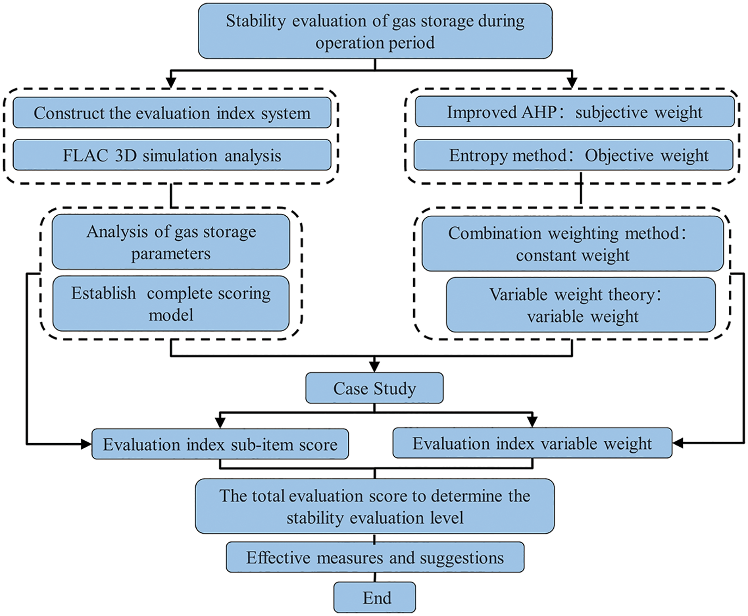
Figure 1: Flow chart of the comprehensive evaluation of stability during the operation period
3 Comprehensive Evaluation Index Weight Calculation
For the comprehensive index evaluation, the constant weight
3.1.1 Improved Analytic Hierarchy Process
(1) Construction of hierarchy model
Set the target level as the top level of the evaluation system. The criterion level and sub-criteria level constitute the middle level of the evaluation system. The evaluation system allows the criterion and sub-criteria layers to be composed of multiple layers; the criteria of the previous level will roughly determine the requirements of the next level. The evaluation object is the lowest level of the hierarchical structure. The sub-criteria level, the criterion level, and the decision-making goal are the bridges to establish the connection with the evaluation object.
(2) Construction of judgment matrix
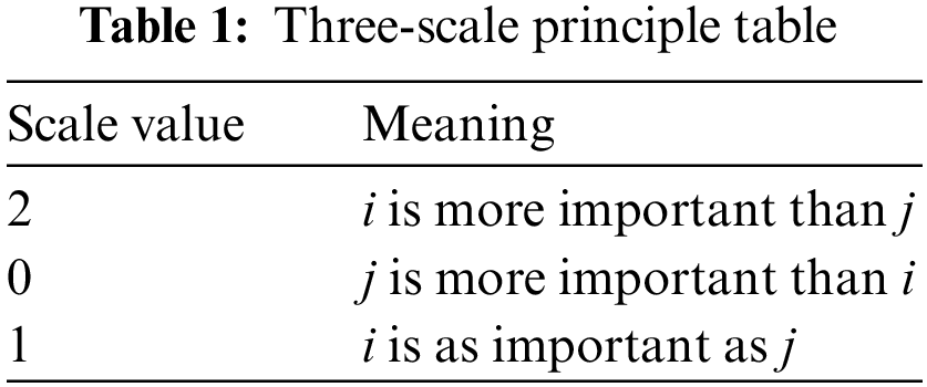
The importance of any two evaluation indicators at each hierarchy level needs to be compared for a specific criterion level of evaluation indicators. The comparison results of the pairwise evaluation index are described by the improved three-scale method. Then the pairwise evaluation judgment matrix A corresponding to the index level is constructed, and the judgment matrix element is the scale value
(3) Hierarchical Single Sorting and Consistency Check
For the eigenvector of the largest eigenroot
CI = 0, there is complete consistency; the closer the CI is to 0, there is satisfactory consistency; the more significant the CI, the more serious the inconsistency.
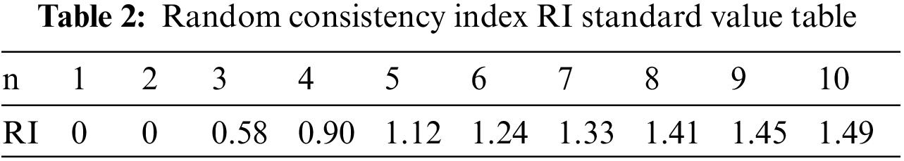
To facilitate the measurement of CI, the random consistency index RI is introduced:
where the random consistency index RI is related to the order of the judgment matrix, and the corresponding relationship is shown in Table 2.
Considering that random reasons may cause the deviation of consistency when testing whether the judgment matrix has satisfactory consistency, it is also necessary to compare CI and RI to obtain the test coefficient CR. The formula is as follows:
Generally, when the test coefficient CR < 0.10, the judgment matrix A is considered to pass the consistency test. Otherwise, it fails.
(4) Improved judgment matrix
Based on the judgment matrix A, it is stipulated that:
Set
Based on the judgment matrix constructed above, to obtain a judgment matrix that satisfies the consistency of judgment, it is necessary to transform the judgment matrix K to a certain extent with the help of the concept of an optimized transfer matrix. Therefore, the transformed judgment matrix can naturally meet the consistency test index CR requirements, and the ranking weight value of the comprehensive evaluation index can be obtained conveniently and directly.
The formula for constructing the transfer matrix is as follows:
The element
The matrix element
Solve the eigenvector
The entropy weight method EWM is an objective weighting method used to measure the amount of information. Based on the degree of variation of each indicator, entropy weight is obtained through information entropy. Information entropy can describe the degree of disorder and the quantitative degree of effectiveness of a natural system. The gas storage operation stability evaluation system is open, and changes due to different places and times. Therefore, the traditional objective weighting method cannot clearly describe the law of influencing indicators. In using the entropy method to construct the judgment matrix in order to determine the index weight, the interference of human factors should be avoided as much as possible, so that the evaluation index assignment result can be more consistent with the actual situation, detached as it is from human bias.
A gas storage with m operating conditions is drawn up, and each operating condition has n evaluation indicators, judgment matrix is constructed:
References the Eq. (24) be normalized:
Quoting Eq. (25) to calculate the entropy value of the evaluation index:
Use Eq. (26) to determine the entropy weight of the evaluation index:
3.1.3 Maximization of Variance
The evaluation index weight calculated by the improved AHP is called the subjective weight [10]. The evaluation index weight estimated by the EWM is called the objective weight, and the combined weight is composed of both the AHP and EWM. The variance maximization method can effectively solve the problem of the distribution of subjective and objective weights. The smaller the evaluation index value difference, the smaller the effect of the index, the smaller the weight is assigned, and the greater the weight is given to it. The combined weight
Normalize the judgment matrix
Refer to Eqs. (27) and (28) to calculate
where
Through calculating subjective weight
Various influencing factors interact in the safety evaluation system, and a poorly graded indicator will seriously impact the evaluation result. Therefore, it is unreasonable to deal with the evaluation index usually [11]. The variable weight theory is one of the essential modeling principles of the factor space theory of Li HX, introducing an equilibrium function based on it, and deriving a more explicit variable weight Eq. (16).
where
The calculation block diagram of the variable weight method for evaluating the operation stability of gas storage is shown in Fig. 2; the constant weight is calculated based on the improved AHP three-scale method and both the EWM, and the combined variable weight are calculated with the variable weight theory.
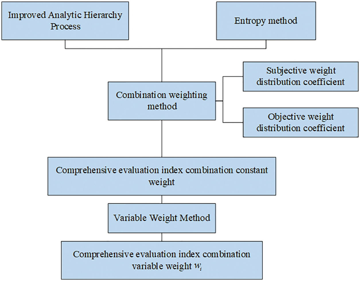
Figure 2: The calculation block diagram of the variable weight method for the operation stability evaluation of the salt cavern UGS
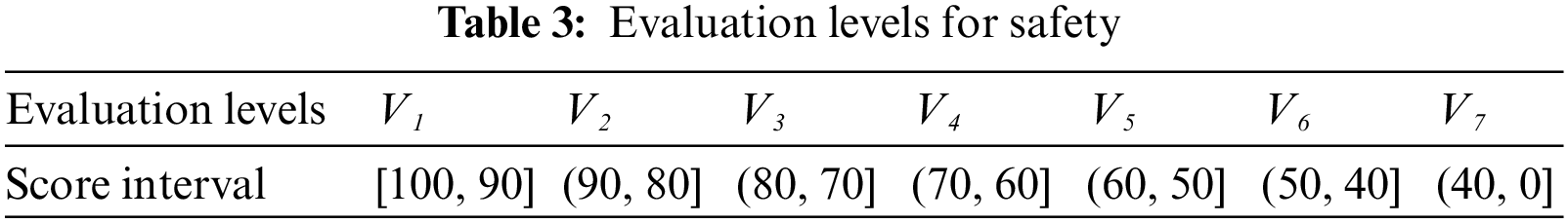
This paper proposes that the long-term stability evaluation set of the interlayer salt rock UGS during the operation period is V = {V1, V2, V3, V4, V5, V6, V7} = {particularly stable, very stable, relatively stable, generally stable, relatively unstable, very unstable, especially unstable}. For the convenience of evaluation, the evaluation set is transformed into a set of values, that is, V = { [100,90], (90,80], (80,70], (70,60], (60,50], (50,40], (40,0]}, and the corresponding score interval division is shown in Table 3 below.
4 Index System and Scoring Model
4.1 Comprehensive Index System
The safe operation of interbedded salt rock UGS is closely related to its long-term stability during its operation period, and as such, is determined by a bevy of influencing factors. The prerequisite and basis for the comprehensive evaluation of the long-term stability of the UGS during an operation period is the need to build a long-term stability evaluation system in the operation period that conforms to its operating rules. he relevant data on the operation stability evaluation of gas storage must be investigated, and combined with the stability standards of the salt rock UGS during the operation period so as to construct a corresponding stability evaluation system for the UGS [12,13]. The comprehensive evaluation system for the stability of the salt cavern UGS during the operation period is shown in Fig. 3.
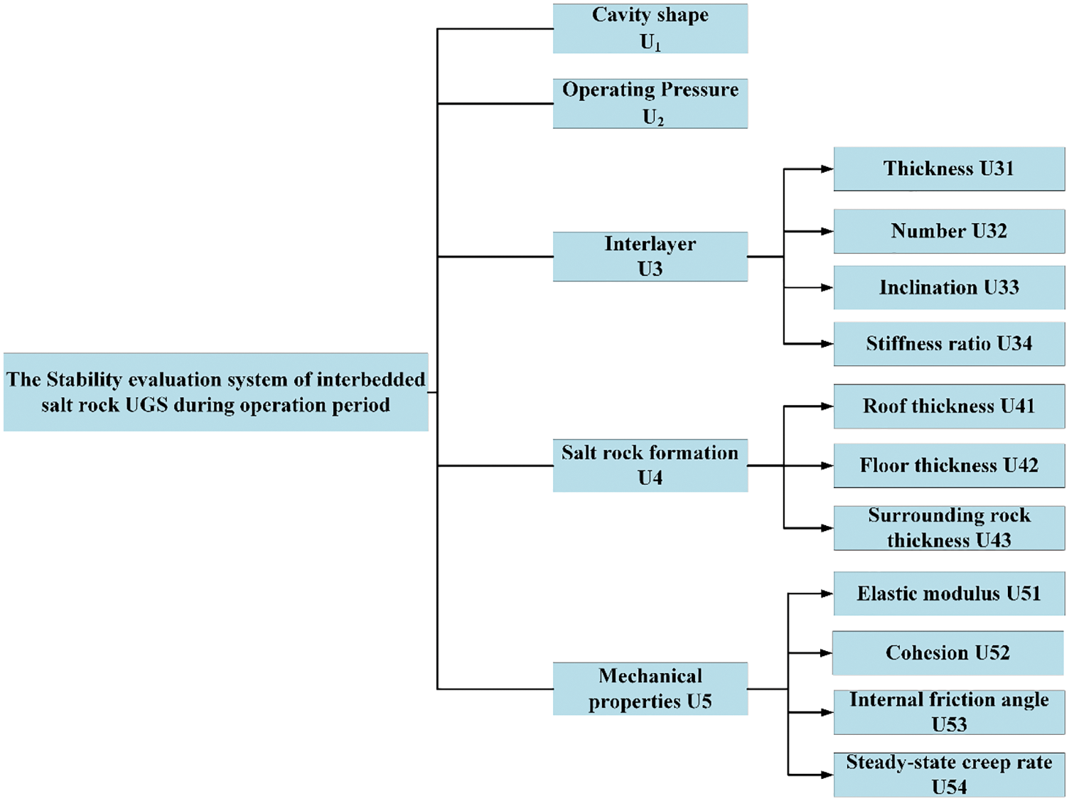
Figure 3: The stability evaluation system of interbedded salt rock UGS during the operation period
This paper uses ANSYS 15.0 finite element software to establish a numerical calculation model for UGS containing interbedded salt rock. The general numerical simulation software FLAC 3D, used for geotechnical engineering, is utilized in analyzing any cavern creep during the long-term operation of underground gas storage containing interbedded salt rock. A simulation study was carried out, and the influence of different parameters on the operation stability of the gas storage was explored in detail. Fig. 4 is a schematic diagram of salt cavern UGS with interlayers. The stratum is composed of alternating salt rock and mudstone layers, forming a stratum geological model. The ellipse represents the dissolved cavity of the salt cavern gas storage. Connected with the tubing string of the external production operation system, the right side is the intake valve, the left side is the exhaust valve, and the right side of the wellhead is provided with a regulating valve.
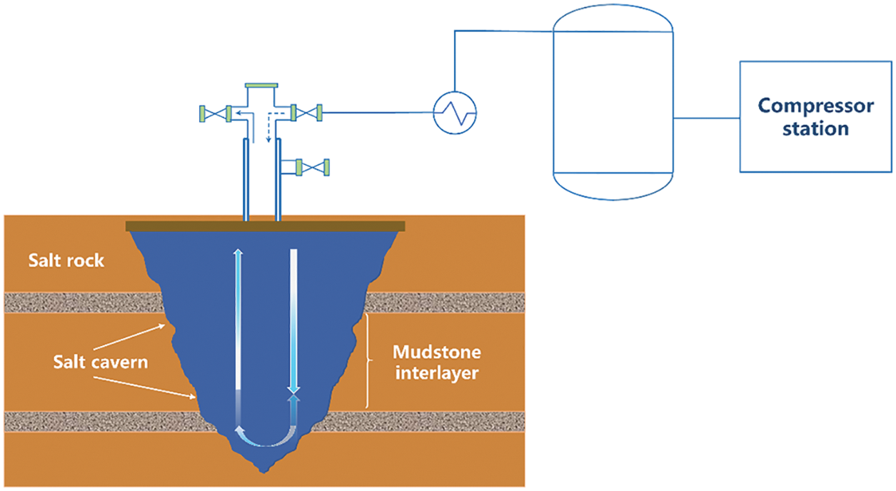
Figure 4: The schematic diagram of salt cavern UGS with interlayer
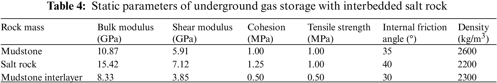
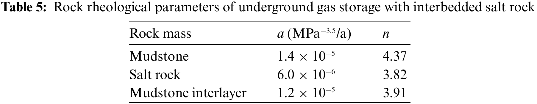
The Norton Power-Law model (MODEL cpower) is selected as the constitutive model for creep calculation of the interbedded salt rock underground gas storage for this work. Based on the corresponding geological survey data of the studied interbedded salt rock underground gas storage, the static parameters and rheological parameters of each rock layer of the established calculation model of the salt rock underground gas storage with interlayer were obtained, as are shown in Tables 4 and 5.
At present [14], the research results show that when the width of the calculation model is more than five times the diameter of the caverns of the salt rock underground gas storage group, the influence of the boundary effect on the deformation of the surrounding rock of the salt rock underground gas storage group can be reasonably ignored. The research object of this paper is a karst cavern of underground gas storage containing an interbedded salt rock with a burial depth of 1000 m. The length and width of the entire calculation area are set to 500 m, and the height is set to 800 m. The short radius is 50 m, the long radius is 80 m, and the interlayer passes through the cavity. The corresponding physical model and numerical calculation model are shown in Fig. 5.
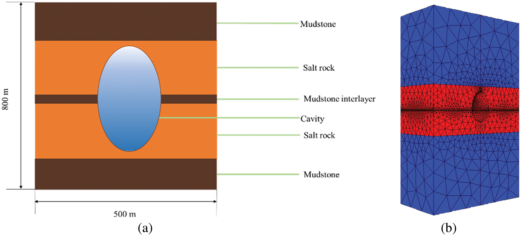
Figure 5: The salt cavity model diagram of UGS with interlayer: (a) Physical model; (b) Numerical calculation model
4.3 Indexes Analysis and Scoring Model
The cavity creeps simulation study was carried out on the cavity shape, operating pressure, and interlayer (thickness, number, inclination, stiffness), salt rock formation (roof, floor, surrounding rock thickness), mechanical properties (elastic modulus, cohesion, internal friction angle, steady-state creep rate). The score models of the corresponding evaluation indexes were determined through analysis of the cavity creep displacement results. This paper uses a percentile system to score each influencing factor to study the stability theory of salt rock gas storage [15,16], combined with the previous comprehensive stability evaluation system, and to obtain the scoring model of each index of the interbedded salt rock gas storage.
The model separately designed three gas storage cavity shapes, namely: ellipsoid, egg-shaped, and spherical, to study the influence of different cavity shapes on the operation stability of the gas storage. Fig. 6 shows the calculation model of the three cavity shapes.
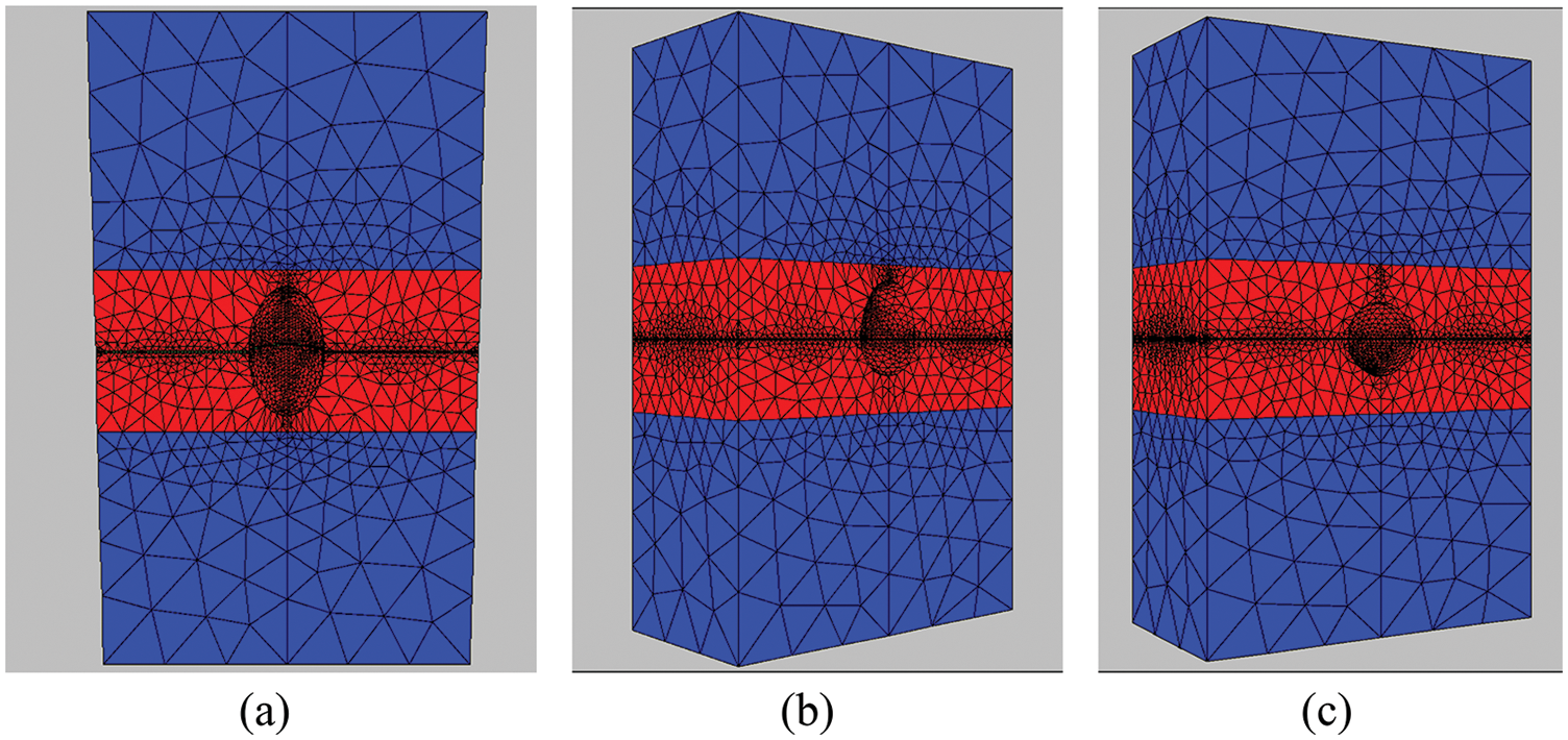
Figure 6: The numerical calculation model diagrams of different cavity shapes for UGS: (a) ellipsoid; (b) egg-shaped; (c) spherical
For specific underground gas storages containing interbedded salt rock, the scoring model of the cavity shape index is shown in Eq. (17).
From Eq. (17), the cavity shape index score decreases linearly with the increase of the cavity creep rate. According to the results of cavern creep displacement, it can be concluded that the three gas storage cavity shapes are: ellipsoidal (82.91), egg-shaped (87), and spherical (86.94).
Operating pressure index scoring model, as shown in Eqs. (18) and (19).
where
Fig. 7 presents the creep displacement result of the cavity under the different operating pressure.s time goes by, the maximum displacement continues to increase, and the volume of the cavern keeps shrinking; under the same operating time, the maximum displacement will decrease with the increase of operating pressure; when the operating pressure is greater than or equal to 8 MPa, the maximum displacement changes approximately linearly with the time; when the operating pressure is lower than 4 MPa, the maximum displacement increases significantly in the first 15 years, and grows slowly in the next 15 years. Therefore, it is reasonable to set 8 MPa as the minimum operating pressure of the underground gas storage with interbedded salt rock. Meanwhile, to avoid leakage of the gas storage due to excessive operating internal pressure during the operation of the gas storage, the operating pressure should also be less than 16 MPa. From Eq. (18), It can be seen that the pressure ratio should be maintained between 1 and 2, and the best value is 1.5.
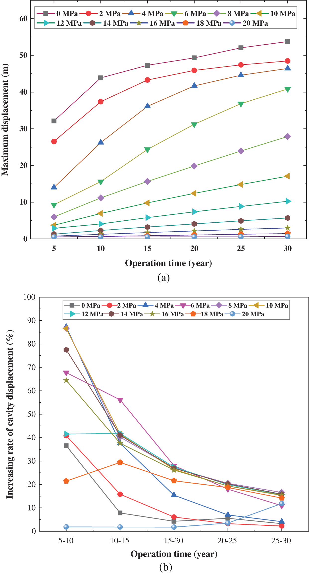
Figure 7: The creep displacement diagram of the salt cavern in different internal pressure: (a) Maximum displacement; (b) Displacement creep rate
This section starts with four aspects of thickness, number, inclination, and stiffness, using the simulation software FLAC 3D to research its stability, and obtain the indexes score model.
The scoring model of the interlayer index is shown in Eqs. (20)~(23).
where
where
where
where
The above formula presents the score model of the interlayer thickness, number, inclination, and stiffness ratio, respectively. As the thickness and quantity of the interlayer increase, it can be seen that corresponding index scores gradually decrease. In the storage construction process, the area with less interlayer thickness and quantity should be selected as much as possible. For the interlayer inclination, 7.5°~17.5° should be chosen as far as possible to maintain stability better. The stiffness ratio is defined as the ratio of the stiffness of the mudstone interlayer to the salt rock. When the stiffness ratio is minimal, the score is particularly susceptible to it in fact, and it increases rapidly with the increase of stiffness ratio, and then slowly increases to the peak value from there. When the stiffness ratio increases, on the other hand, the index scoring gradually begins to decrease. When the stiffness ratio takes the maximum and minimum values, the corresponding index scores are lower. In actual, practical engineering applications, we are trying to keep the stiffness ratio between 2 and 4, where 3 is the best.
For the long-term safe operation of the interbedded salt rock underground gas storage, setting a certain thickness of the roof salt rock layer can offset or weaken the influence of the cavern deformation caused by the salt rock creep on the upper rock layer and the ground surface. The actual field experience shows that the low permeability of the roof and floor of the salt cavern and the surrounding salt rock layer guarantee the tightness and stability of the salt rock UGS. The salt rock layer index includes three sub-indices: the roof thickness, the floor thickness, and the thickness of the surrounding salt rock.
where
d is the maximum diameter of the salt cavern, m.
From the above score model, As the thickness of the roof salt rock increases, the stability score gradually rises; when the value is 0.5 to 1, the score is the highest and continues to increase, the stability is quickly destroyed until the score tends to 0. As floor thickness and surrounding thickness index are similar to the score of roof thickness, not the same. In practical engineering applications, the site should be selected for construction where the roof, floor, and surrounding thickness are close to the diameter of the cavern.
The mechanical properties of salt rock include elastic modulus, cohesion, internal friction angle, and steady-state creep rate. The scoring model of mechanical properties is shown in Eqs. (27)~(30), respectively.
where
where
where
where
For the elastic modulus, it is to determine the elastic modulus stress required to plastically deform under the applied force of rock salt. The greater the elastic modulus, the stronger the ability of the salt rock to resist external deformation, and, accordingly, the less likely it is to deform during actual operation. The higher the elastic modulus, the better the stability; in real engineering applications, attempting to choose high elastic modulus to build the UGS with remains critical. Salt rock cohesion is defined as the mutual attraction between adjacent parts of the rock, which reflects the strength of the salt rock to a certain extent; the greater the cohesion, the greater the mechanical strength of the salt rock. The internal friction angle reflects the shear strength of salt rock. The higher the internal friction angle, the better the salt rock gas storage stability. Therefore, the high internal friction angle should be selected as far as possible to ensure the operational stability of the salt rock gas storage. The creep rate refers to the derivative of elongation to the time when the salt rock undergoes creep deformation; the lower the steady-state creep rate, the less prone to deformation of the salt rock, the stronger the ability to resist external stress interference, and the better the stability of salt rock gas storage [17].
5.1 Underground Gas Storage Parameters
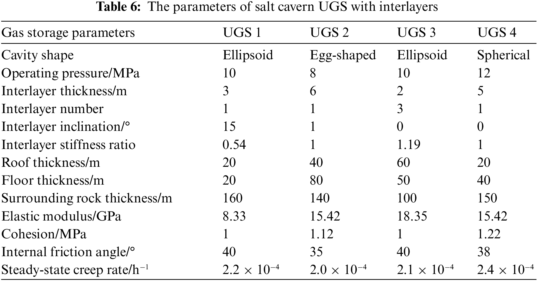
According to the research results above, with further evidence and work demonstrated and explained below, a comprehensive stability evaluation of the salt cavern UGS during the operation period was carried out. Four salt cavern UGS under four different operating conditions are given in the study. The cross-section view of the UGS is shown in Fig. 8, and the specific parameters are shown in Table 6.
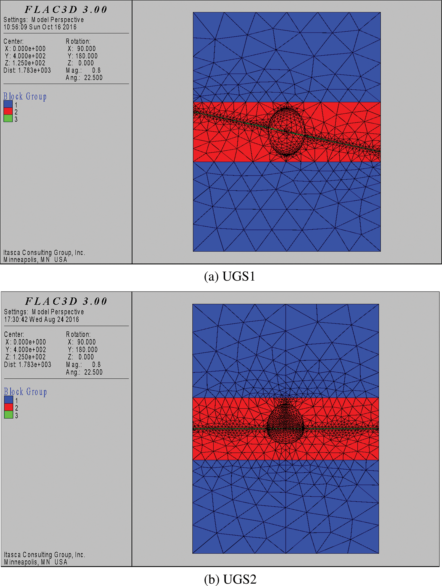
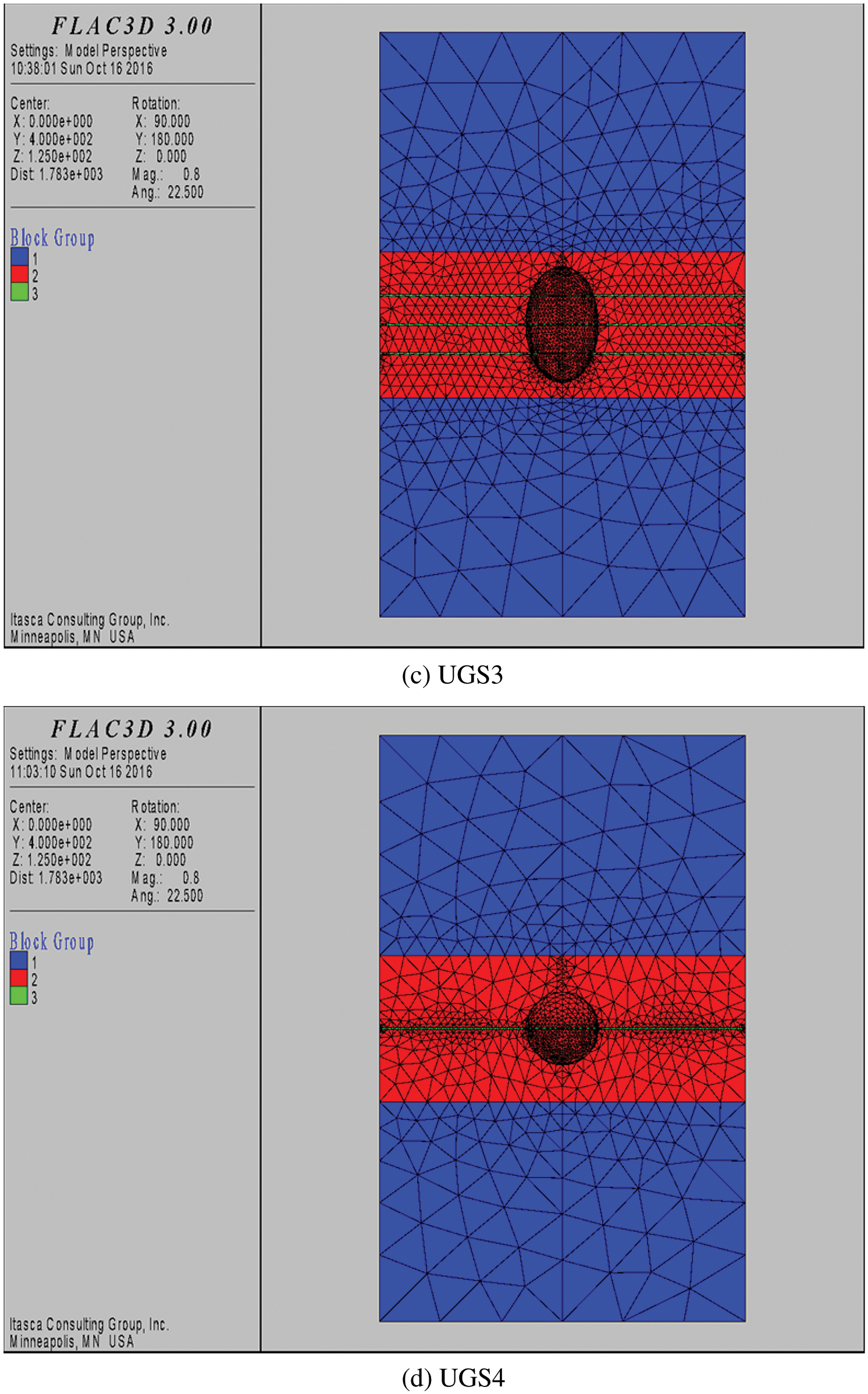
Figure 8: The cross-section view of the salt cavern UGS with interlayers: (a) UGS 1; (b) UGS 2; (c) UGS 3; (d) UGS 4
5.2 Gas Storage Operators Stability Evaluation
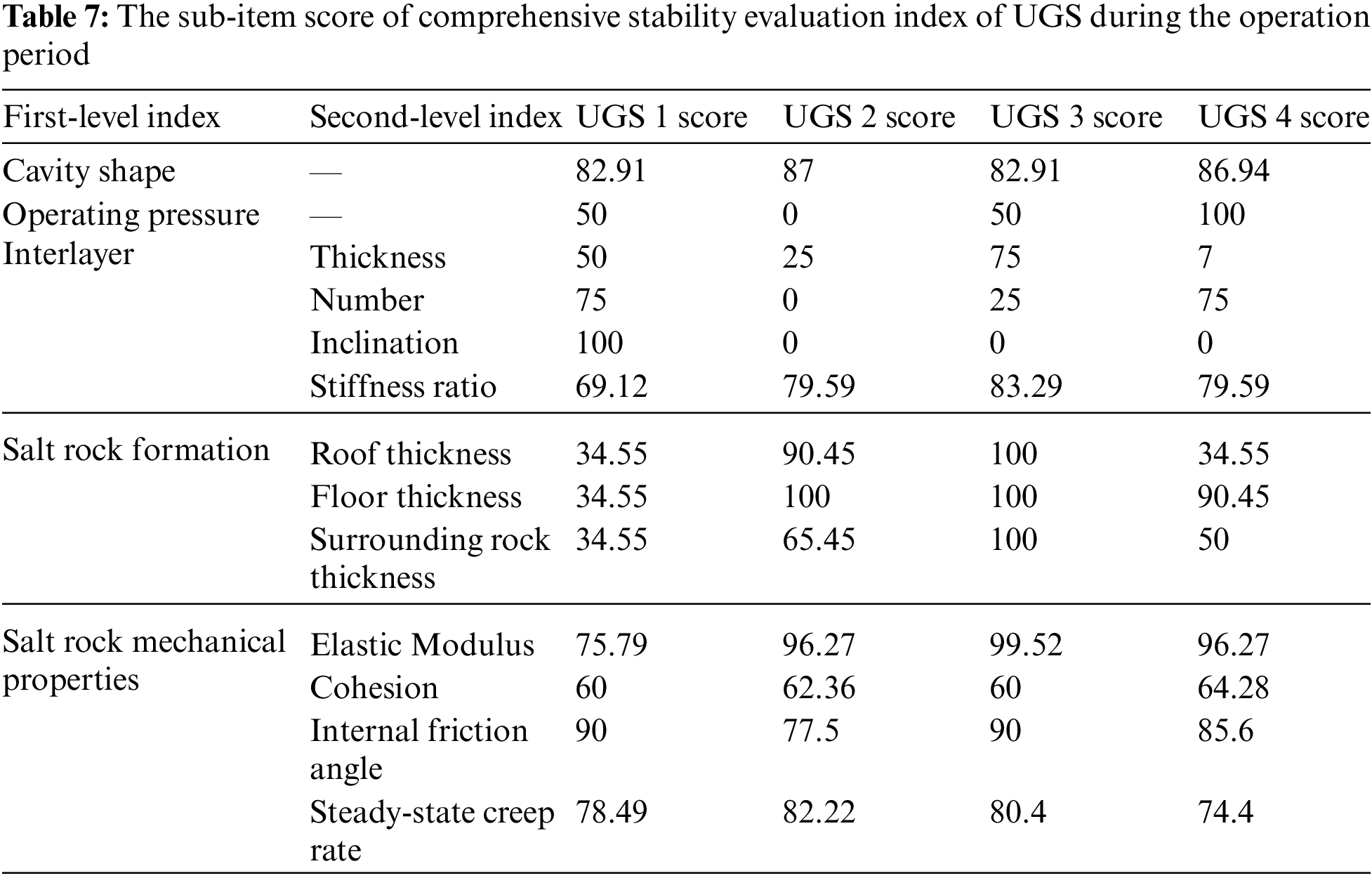
According to the parameter Table 6, substituting the evaluation index parameter scoring model to obtain the sub-item score of each index of the UGS, as shown in Table 7.
According to the various factors that affect the stability of the interbedded salt rock underground gas storage during the long-term operation, the sub-indices of the interlayer, the surrounding salt rock formations, and the mechanical characteristic parameters of the salt rock are all compared in pairs. Based on the improved AHP, the corresponding index level comparison judgment matrix is constructed, and the judgment matrix is shown in Eq. (31).
where
According to the various factors that affect the stability of the interbedded salt rock underground gas storage during the long-term operation, the first-level indicators (mainly including the cavity shape, operating pressure, interlayer, surrounding salt rock layer, and mechanical properties of the salt rock) that affect the long-term stability of the salt rock underground gas storage during the operation period were compared. The result of the judgment matrix is shown in Eq. (32).
where
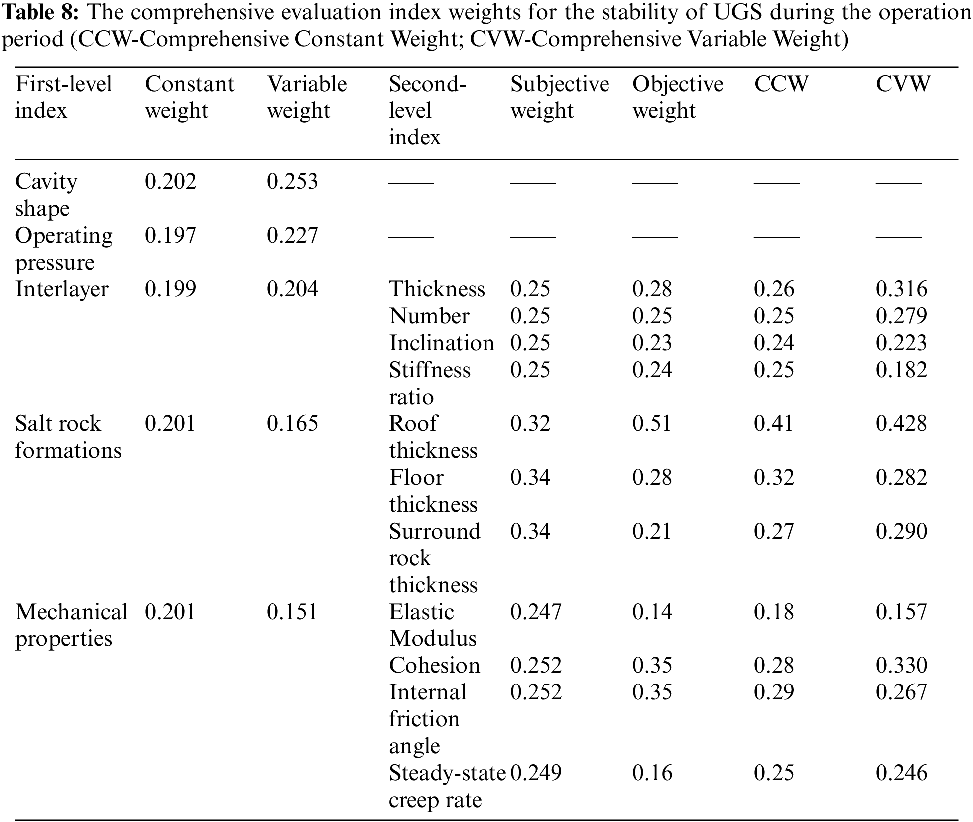
Based on the theories of variable weight method and constant weight method given above, combined with the evaluation index judgment matrix Eqs. (31) and (32), the comprehensive evaluation index weight is calculated. The results are shown in Table 8.
Based on the variable weight method, the total long-term stability comprehensive evaluation scores for the four given working conditions of the interbedded salt rock UGS during the operation period are 63.38, 52.32, 70.14, and 72.52, respectively. Meanwhile, referring to the long-term stability evaluation grade table of the underground gas storage with an interbedded salt rock during the operation period, it is judged that the operation stability grades of the four design conditions of the gas storage are generally stable, relatively unstable, relatively stable, and relatively stable. It shows that the stability of the underground gas storage with interbedded salt rock under the four given working conditions is generally good in the long-term operation process. The cavern construction and operation management are reasonable. The cavern construction method and operation management measures are conducive to the safe operation of the salt cavern UGS under the four conditions.
According to the calculation of the traditional constant weight evaluation method, the total scores of the four different conditions of UGS stability evaluation are 63.97, 55.91, 72.23, and 73.11. Considering the thick interlayer and poor mechanical parameters of the UGS2, therefore, under the evaluation of constant weight and variable weight, the total score is the lowest, which should be avoided as much as possible in the actual scene. Analysis Fig. 9, a comprehensive comparison of the evaluation results of constant weight and variable weight, found that the overall stability evaluation score obtained by the variable weight method is relatively low. This fully illustrates that the comprehensive evaluation of the long-term stability of the interbedded salt rock underground gas storage during the operation period using the variable weight method is relatively more stringent. It provides a better way to help the operation and management personnel of the salt cavern UGS genuinely grasp the most accurate conditions of the gas storage and take more effective control measures.
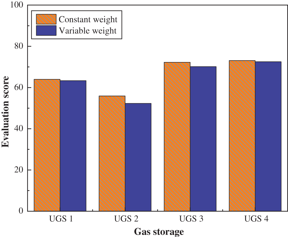
Figure 9: Stability evaluation score comparison of salt cavern UGS in operation period based on constant weight and variable weight method
With the rapid development and structural transformation of the energy industry, the energy supply system gradually presents the uncertainty of operation and the imbalance of supply and demand. Therefore, as an important peak-shaving facility, underground energy storage is required to maintain high stability in the case of large fluctuations in operating parameters. This paper focuses on the stability evaluation of salt cavern UGS with interlayers, and innovatively proposes a stability evaluation index system and comprehensive evaluation model for salt cavern UGS with interlayers. Based on the proposed stability evaluation method, it can effectively identify the instability factors of underground energy storage, thus providing more scientific and theoretical guidance for field operation control. The conclusions of this paper are as follows:
(1) Construct a comprehensive evaluation system for the stability influencing factors of the interbedded salt rock UGS during the operation period. Through FLAC 3D simulation of the cavern creep of the UGS, determining the scoring model corresponding to each index.
(2) To improve the accuracy of the stability evaluation of salt cavern UGS, the index weights are constructed in the form of combined weights. The improved AHP calculates the subjective weight of each index, and the objective weight of each index is calculated by the entropy method.
(3) When constructing the dissolution cavity, the egg shape and spherical shape are suitable. Try to choose the rock formation with greater stiffness. during operation, control the operating pressure range of 8 to 16 MPa; additionally, try to choose the formation with an interlayer inclination angle of about 15° to ensure the operation stability of the salt rock UGS.
(4) The case study shows that, compared with the constant weight method, the stability evaluation using the variable weight method is more rigorous and objective. The combination variable weight theory is applied to the stability evaluation of engineering gas storage, which can further improve the accuracy of the evaluation results.
Statement of Data Availability:All data, models, and code generated or used during the study appear in the submitted article.
Funding Statement: This work was supported by the National Natural Science Foundation of China [51704253].
Conflicts of Interest:The authors declare that they have no conflicts of interest to report regarding the present study.
References
1. Zhang, J. D., Tan, Y. F., Zhang, T., Yu, K. C., Wang, X. M. et al. (2020). Natural gas market and underground gas storage development in China. Journal of Energy Storage, 29, 101338. DOI 10.1016/j.est.2020.101338. [Google Scholar] [CrossRef]
2. Dostál, Z., Ladányi, L. (2018). Demands on energy storage for renewable power sources. Journal of Energy Storage, 18, 250–255. DOI 10.1016/j.est.2018.05.003. [Google Scholar] [CrossRef]
3. Menzel, W., Schreiner, W. (1989). Geomechanical aspects for the establishment and the operation of gas cavern stores in salt formations of the GDR. International Journal of Rock Mechanics and Mining Sciences & Geomechanics Abstracts, 29(1), 115–120. [Google Scholar]
4. Wang, T., Yan, X. Z., Yang, H. L., Yang, X. J. (2011). Stability analysis of the pillars between bedded salt cavern gas storages by cusp catastrophe model. Science China Technological Sciences, 54(6), 1615–1623. DOI 10.1007/s11431-011-4401-5. [Google Scholar] [CrossRef]
5. Wang, T., Ma, H. L., Shi, X. L., Yang, C. H., Zhang, N. et al. (2018). Salt cavern gas storage in an ultra-deep formation in Hubei. China International Journal of Rock Mechanics and Mining Sciences, 102(15), 57–70. DOI 10.1016/j.ijrmms.2017.12.001. [Google Scholar] [CrossRef]
6. Yin, H. W., Yang, C. H., Ma, H. L., Shi, X. L., Zhang, N. et al. (2020). Stability evaluation of underground gas storage salt caverns with micro-leakage interlayer in bedded rock salt of Jintan. China Acta Geotechnica, 15(3), 549–563. DOI 10.1007/s11440-019-00901-y. [Google Scholar] [CrossRef]
7. Yan, F., Yi, F. H., Chen, L. (2019). Improved entropy weighting model in water quality evaluation. Water Resources Management, 33(6), 2049–2056. DOI 10.1007/s11269-019-02227-6. [Google Scholar] [CrossRef]
8. Tunsakul, J., Jongpradist, P., Kim, H. M., Nanakorn, P. (2018). Evaluation of rock fracture patterns based on the element-free Galerkin method for stability assessment of a highly pressurized gas storage cavern. Acta Geotechnica, 13(4), 817–832. DOI 10.1007/s11440-017-0594-5. [Google Scholar] [CrossRef]
9. Bi, A., Luo, Z., Kong, Y., Zhao, L. (2020). Comprehensive weighted matter-element extension method for the safety evaluation of underground gas storage. Royal Society Open Science, 7(4), 191302. DOI 10.1098/rsos.191302. [Google Scholar] [CrossRef]
10. Zhang, F. Y., Geng, B., Li, D. Y., Liu, Z. L. (2014). Study on comprehensive weighting method based on subjective and objective weights. Advances in Intelligent Systems Research, 101, 737–741. DOI 10.2991/lemcs-14.2014.169. [Google Scholar] [CrossRef]
11. Yan, Q. Y., Zhang, M. J., Li, W., Qin, G. Y. (2020). Risk assessment of new energy vehicle supply chain based on variable weight theory and cloud model: A case study in China. Sustainability, 12(8), 1–22. DOI 10.3390/su12083150. [Google Scholar] [CrossRef]
12. Hwang, D. Y., Taha, B., Lee, D. S., Hatzinakos, D. (2021). Evaluation of the time stability and uniqueness in PPG-based biometric system. IEEE Transactions on Information Forensics and Security, 16, 116–130. DOI 10.1109/TIFS.2020.3006313. [Google Scholar] [CrossRef]
13. Takei, Y., Yoshida, H., Komatsu, E., Arai, K. (2021). Uncertainty evaluation of the static expansion system and its long-term stability at NMIJ. Vacuum, 187(1–2), 110034. DOI 10.1016/j.vacuum.2020.110034. [Google Scholar] [CrossRef]
14. Ning, Z. X., Xue, Y. G., Su, M. X., Qiu, D. H., Zhang, K. et al. (2021). Deformation characteristics observed during multi-step excavation of underground oil storage caverns based on field monitoring and numerical simulation. Environmental Earth Sciences, 80(6), 222. DOI 10.1007/s12665-021-09496-8. [Google Scholar] [CrossRef]
15. Habibi, R., Moomivand, H., Ahmadi, M., Asgari, A. (2021). Stability analysis of complex behavior of salt cavern subjected to cyclic loading by laboratory measurement and numerical modeling using LOCAS (Case study: Nasrabad gas storage salt cavern). Environmental Earth Sciences, 80(8), 317. DOI 10.1007/s12665-021-09620-8. [Google Scholar] [CrossRef]
16. Li, W. J., Miao, X., Yang, C. H. (2020). Failure analysis for gas storage salt cavern by thermo-mechanical modelingmodelling considering rock salt creep. Journal of Energy Storage, 32, 102004. DOI 10.1016/j.est.2020.102004. [Google Scholar] [CrossRef]
17. Shi, X. L., Liu, W., Chen, J., Yang, C. H., Li, Y. P. et al. (2017). Geological feasibility of underground oil storage in Jintan salt mine of China. Advances in Materials Science & Engineering, 2017(1), 1–11. DOI 10.1155/2017/3159152. [Google Scholar] [CrossRef]
Cite This Article
 Copyright © 2023 The Author(s). Published by Tech Science Press.
This work is licensed under a Creative Commons Attribution 4.0 International License , which permits unrestricted use, distribution, and reproduction in any medium, provided the original work is properly cited.
 Downloads
 Citation Tools