
 Submit a Paper
 Propose a Special lssue
 Open Access
ARTICLE
Data Mining Based Integrated Electric-Gas Energy System Multi-Objective Optimization
1 North China Electric Power University, Beijing, 102206, China
2 State Grid Integrated Energy Service Group, Beijing, 100052, China
* Corresponding Author: Zhukui Tan. Email:
Energy Engineering 2022, 119(6), 2607-2619. https://doi.org/10.32604/ee.2022.019550
Received 29 September 2021; Accepted 15 February 2022; Issue published 14 September 2022
 View Full Text
 Download PDF
Abstract
With the proposal of carbon neutrality, how to improve the proportion of clean energy in energy consumption and reduce carbon dioxide emissions has become the important challenge for the traditional energy industry. Based on the idea of multi-energy complementarity, a typical integrated energy system consisting of electric system and gas system is constructed based on the application of power to gas (P2G) technology and gas turbine in this paper. Furthermore, a multi-objective optimization model with economic improvement, carbon emission reduction and peak-load shifting as objectives is proposed, and solved by BSO algorithm. Finally, a typical power-gas coupling system is selected as an example to verify the effectiveness of the model. The results showed that the proposed multi-objective optimization model based on BSO algorithm can better play the complementary characteristics of the electric and gas system, and significantly improve the comprehensive benefits of system operation.Keywords
At present, China is undergoing profound energy reform [1]. China vigorously advocates the concept of green development. Energy consumption supply, energy structure transformation and energy system form all present the development trend of network, intelligence and digitalization [2]. After the double carbon target was proposed, the development of clean energy accelerated, and the connection between different energy systems became closer. At the same time, the development of integrated energy services improves energy efficiency, reduces energy consumption costs, and promotes competition and cooperation [3].
The core problem of integrated energy system development lies in system operation optimization [4], which has been studied by experts and scholars at home and abroad. Li et al. [5] established a model for optimal scheduling of thermal and electric energy integrated energy system, and verified the benefits of the model in fuel saving, clean energy consumption, capacity saving and other aspects with actual grid data based on considering the reserve benefits of heat storage tank and operation strategy. Cong et al. [6] constructed the asynchronous operation mechanism and framework of the power-natural gas joint market with the participation of comprehensive energy service providers, established a two-stage nested two-layer optimization model of the integrated energy system, which can improve the operation efficiency, reliability and flexibility of the integrated energy system. Natural gas has the advantages of high energy efficiency, low emissions and strong controllability [7], so it plays a crucial role in the development of integrated energy system. However, the uncertainty of natural gas pressure energy and the random fluctuation of pipe network load limit the improvement of pressure energy utilization efficiency in the integrated energy system [8]. There are some limitations in the current research, the coupling depth of electricity and gas is not enough. Natural gas is only taken as a primary energy, the deep coupling between electricity and gas and the constraint of natural gas network are not considered.
In view of this situation, basis on the electric power network and natural gas network operation characteristic, this paper puts forward a kind of electricity-gas coupling integrated energy system multi-objective optimization scheduling model which considering economic benefit, environmental benefit and peak-load shifting benefit, and provides theoretical support for the comprehensive benefit improvement of integrated energy system.
2 Power-Gas Coupling System IES Multi-Objective Optimization System
As shown in Fig. 1, the power-gas coupling system consists of an electric power network and a natural gas network, and realizes the conversion of electric energy through P2G and gas turbine. P2G can convert surplus wind power output into natural gas. Therefore, the electric energy input of P2G can be regarded as the charge of the power network, while its natural gas output can be regarded as the source of the natural gas network. On the contrary, the gas turbine converts natural gas into electricity, so the natural gas input of the gas turbine is regarded as the charge of the natural gas network, and its electrical energy output is regarded as the source of the power network [9]. The multi-objective optimal scheduling of power-gas coupling system is to achieve the optimal operation state of the entire power-gas coupling system by coordinating the economic, low-carbon and peak-load shifting objectives on the premise of satisfying the load supply [10,11] and the security constraints of power and natural gas networks.
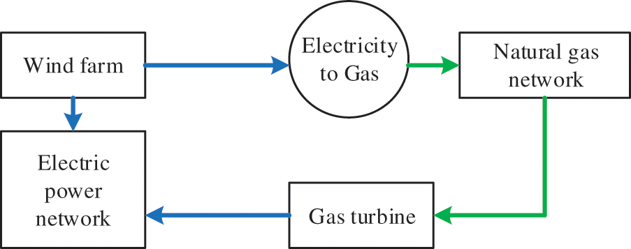
Figure 1: Frame diagram of power-gas coupling system
(1) Economic objective
The economic objective of the multi-objective optimal scheduling of the electrical coupling system is to minimize the operating cost of the system [12], including the cost of coal-fired power generation, the cost of natural gas purchase and the cost of wind curtailment.
where:
(2) Carbon emission objective
The carbon emission of the power-gas coupling system in the whole operation cycle is the difference between the sum of CO2 emitted by coal-fired units and gas turbines and CO2 consumed by power-gas conversion.
where:
(3) Peak-load shifting objective
The goal of multi-objective optimal scheduling of power-gas coupling system is to minimize net power load variance.
where:
The constraints of multi-objective optimal scheduling of power-gas coupling system include power subsystem constraints, natural gas subsystem constraints and coupling constraints of their networks [13,14].
2.3.1 Power Network Constraints
Power network constraints include node power balance constraints, unit active power output constraints, unit climbing constraints, node voltage constraints and branch capacity constraints, as follows:
where: the variables labeled max and min are the upper and lower limits of the corresponding variables, respectively;
2.3.2 Natural Gas Network Constraints
Like the power network, the natural gas network can also be regarded as composed of source, network, load, storage, etc. [15]. The natural gas provided by the gas source is transmitted to the user through the pressure station and natural gas pipeline. At the same time, the gas storage tank can also play the role of storing natural gas and replacing the gas source [16].
(1) Gas source
The gas source is similar to a generator, injecting natural gas into the natural gas network, and each gas source must meet the output flow limit.
where:
(2) Pipelines
The transmission flow in natural gas pipeline is mainly related to the pressure of the nodes on both sides of the pipeline and the transmission characteristics of the pipeline [17].
where:
where:
(3) Pressure station
Due to friction resistance in natural gas pipelines, part of the energy will be lost in the transmission process, resulting in pressure drop. Therefore, a certain number of pressure stations should be installed in the natural gas network to ensure reliable transmission of natural gas.
Pressure stations mainly use compressors to increase the pressure. The compressors consume natural gas, and their consumption is related to the natural gas flow through the compressors and the compression ratio:
where:
(4) Storage tank
When the natural gas load fluctuates greatly or the natural gas network breaks down, the gas storage tank can be used as an alternative gas source to ensure the reliable supply of natural gas [18]. Similar to power network energy storage devices, gas storage tanks should meet the following constraints:
where:
(5) Flow balance
Similar to node power balance constraint in power network, natural gas network also needs to meet node flow balance constraint:
where:
Coupling constraints between power network and natural gas network include P2G constraint and gas turbine constraint.
(1) P2G
P2G constraint including power transformation equation and maximum output gas flow restrictions.
where:
(2) Gas turbine
Gas turbine constraint also include power conversion equations and output active power limits [19,20]. Since the output active power limit is included in the unit active power output constraint of Eq. (13), only the power conversion equation is described here.
where:
3 Solving of the Optimization Problem
BSO (Brain Storm Optimization) is a swarm intelligence optimization algorithm, compared with other algorithms, such as genetic algorithm, PSO algorithm, etc., BSO algorithm can use one or two “old” individuals or groups to generate new individuals, new groups, and thus out of the original search range, and effectively avoid falling into the local optimum. The core idea is to simulate the crowd to propose a large number of solutions to problems. Each solution is regarded as a feasible solution, and the process of obtaining the optimal solution through discussion and integration. It has the advantages of good stability, high accuracy, and fast convergence [21]. In view of this, this paper uses the BSO algorithm to solve the multi-objective optimization problem of electrically coupled system operation. The solution process is shown in Fig. 2. The main steps of the solution are as follows [22]:
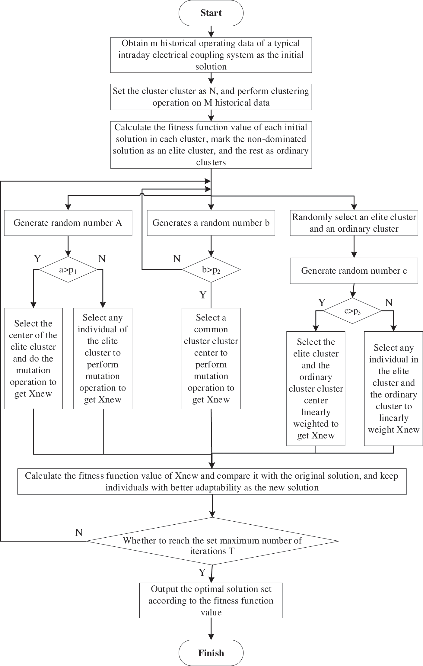
Figure 2: Schematic diagram of multi-objective optimization solution flow of electrical coupling system based on BSO
(1) Initial solution population is generated
Obtain m pieces of historical data of a typical intraday electrical coupling system as the initial feasible solution of the optimization problem. Perform clustering operations on m initial feasible solutions to obtain n clusters of initial solution populations, and calculate the fitness function value of each initial feasible solution. The clusters containing at least one non-dominated solution are marked as elite clusters, and the clusters without non-dominated solutions are marked as ordinary clusters.
(2) Generation of new solutions
In BSO algorithm, new solutions are generated in the following ways:
(1) Select a random elite cluster and generate a random number
(2) Generate a random number
(3) Select an elite cluster and a common cluster, and generate random number
(4) Calculate the fitness function value of the new individual and compare it with the original solution, and keep the individual with good fitness function value as the new solution.
Among them, the mutation operation is achieved by adding random values to selected individuals, and the mutation operation is as follows:
(3) Solution generation of multi-objective optimization problem
Repeat (1) and (2) until the number of iterations reaches the set value T, and then output the optimal solution set according to the fitness function value.
4 Empirical Example and Analysis
This article takes the modified IEEE39-node electric power network and 20-node natural gas network interconnection electrical coupling system as the object, takes one day as the analysis period and 1 h as the scheduling period, to analyze and test the effectiveness of the model proposed in this article. The schematic diagram of the electrical coupling system is shown in Fig. 3.
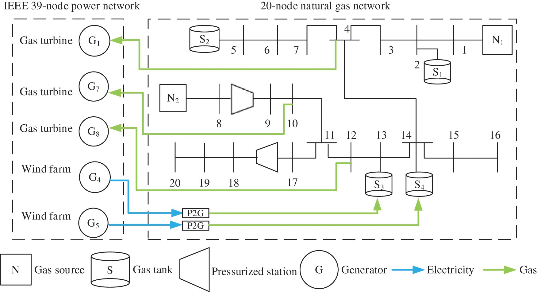
Figure 3: The schematic diagram of the electrical coupling system
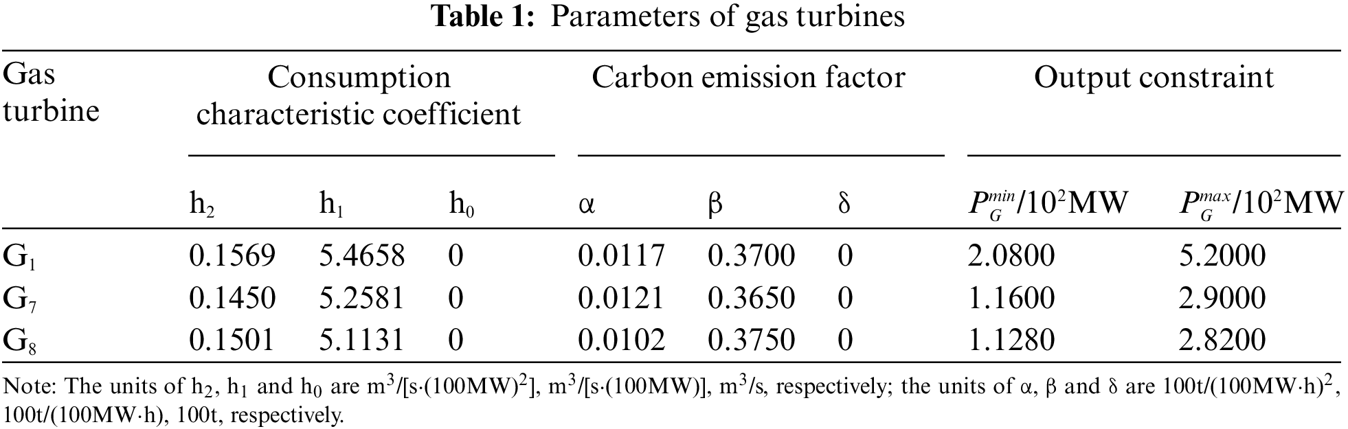
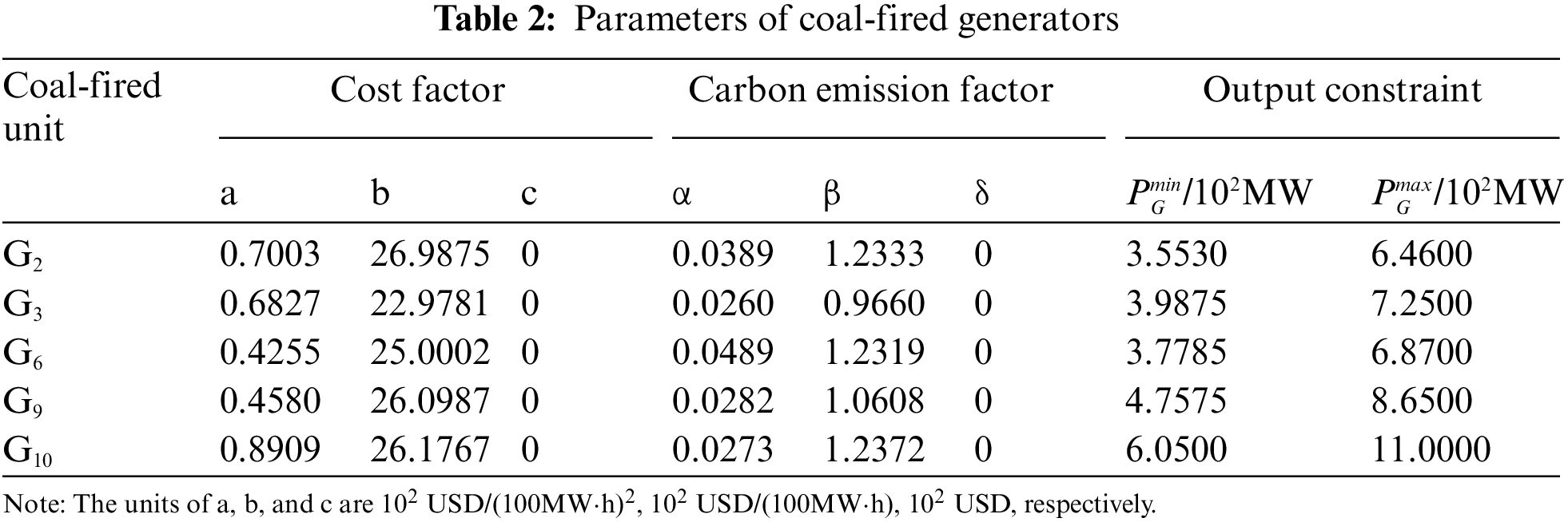
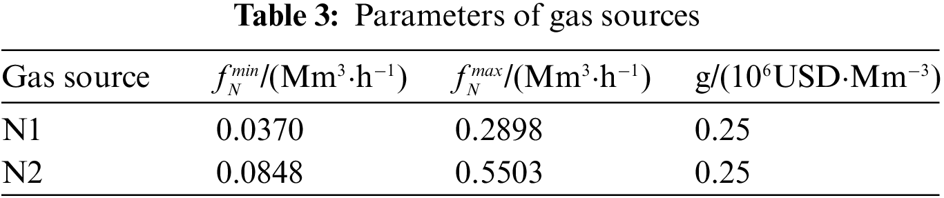
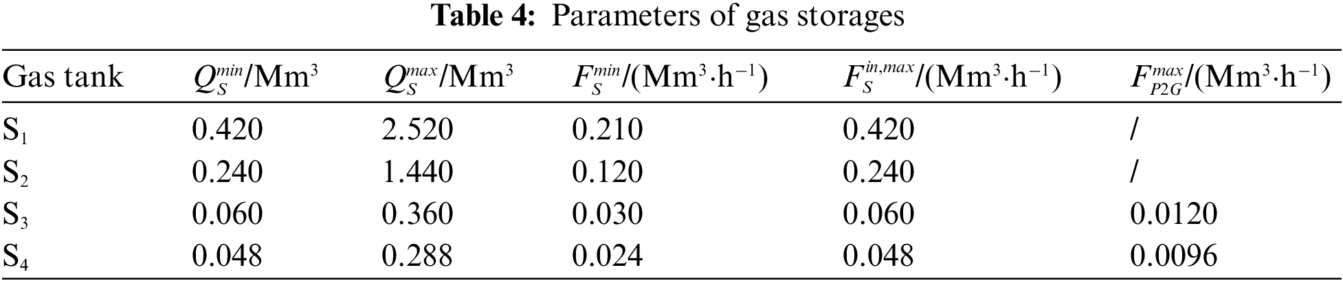
The load of each node of the power sub-network becomes 80% of the IEEE 39-node power network standard test network, units G1, G7 and G8 are gas turbines, connected to load nodes 4, 10 and 12 of the natural gas network, units G4 and G5 are wind farms with a rated power of 600 MW, both wind farms are equipped with P2G equipment and are connected to natural gas network gas storage tanks S3 and S4. The wind farm abandonment penalty coefficient is both US$ 50(MW·h). The remaining units in the power network are coal-fired units. The parameters of gas turbine and coal-fired units are shown in Tables 1 and 2. The natural gas sub-network contains 20 nodes and 19 pipelines, parameters of gas source and storage are shown in Tables 3 and 4, respectively.
In the dispatch day, the available wind farm power, electrical load and gas load of the system are shown in Fig. 4.
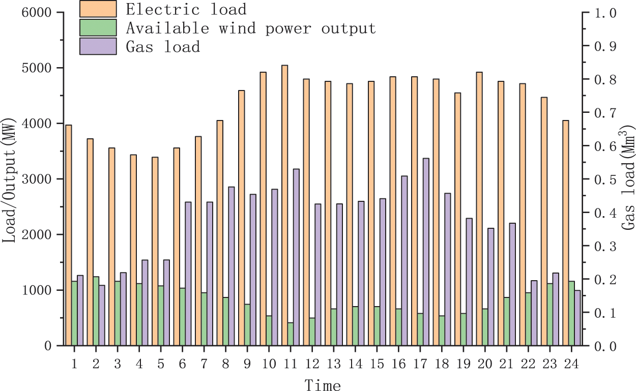
Figure 4: Available wind power, electric and gas load
In order to fully illustrate the superiority of the multi-objective optimal scheduling of the electric-to-gas-electric coupling system in this article, two scenarios are designed for the calculation example: one is a single-objective optimization scenario that targets economy, and the other is a three-objective optimization scenario that targets economy, carbon emissions, and the comprehensive benefits of peak shaving and valley filling. In order to make full use of wind power to reduce operating costs and carbon emissions, the output of wind farms under Scenario 2 of this article is consistent with Scenario 1.
Make the weights of each target in Scenario 2 equal, the wind farm output corresponding to the optimal solution of the single target in Scenario 1 and the compromise solution of multiple targets in Scenario 2, gas turbine output. The injection power of electric-to-gas and the net electric load are shown in Figs. 5 and 6. The corresponding wind power consumption ratio and each target value are shown in Fig. 7.
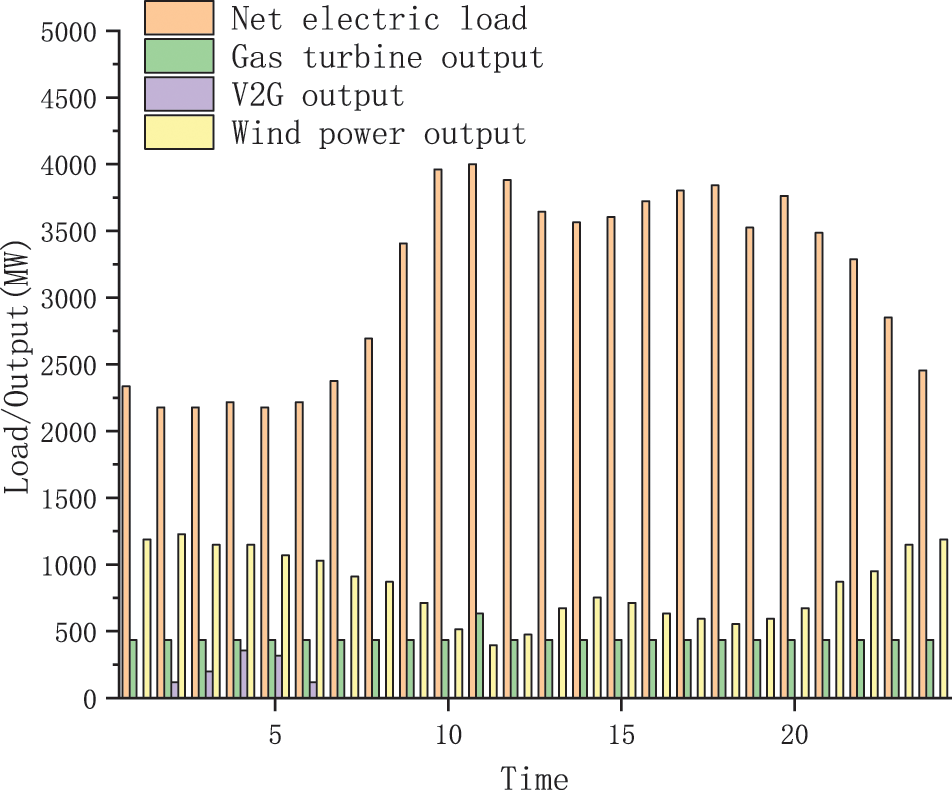
Figure 5: Simulation results in scene 1
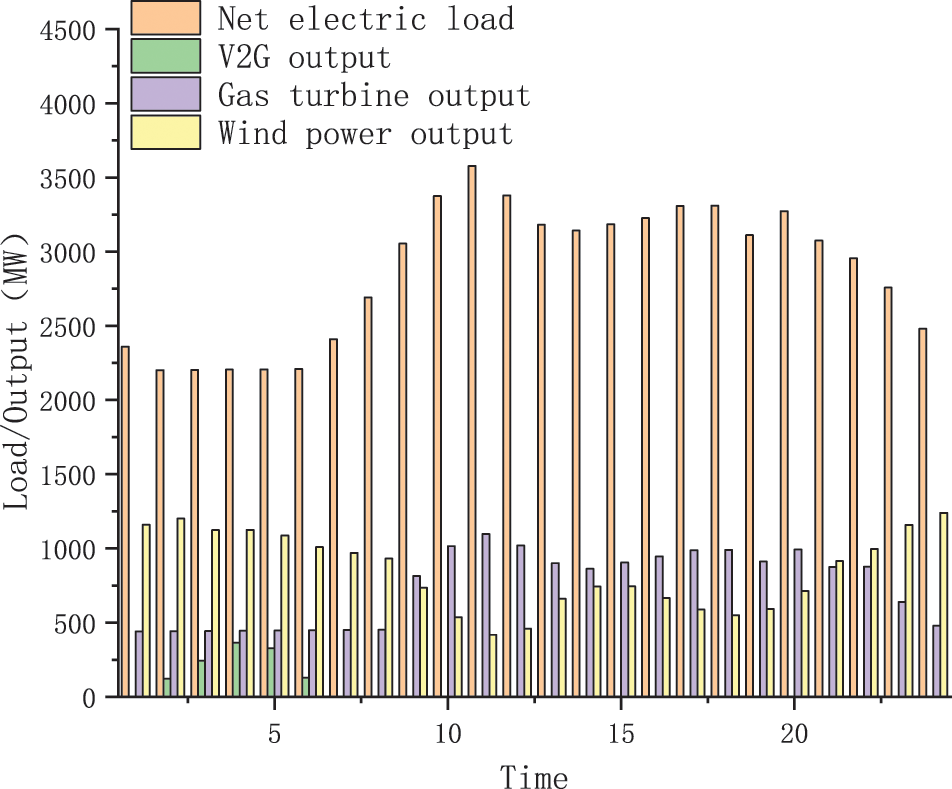
Figure 6: Simulation results in scene 2
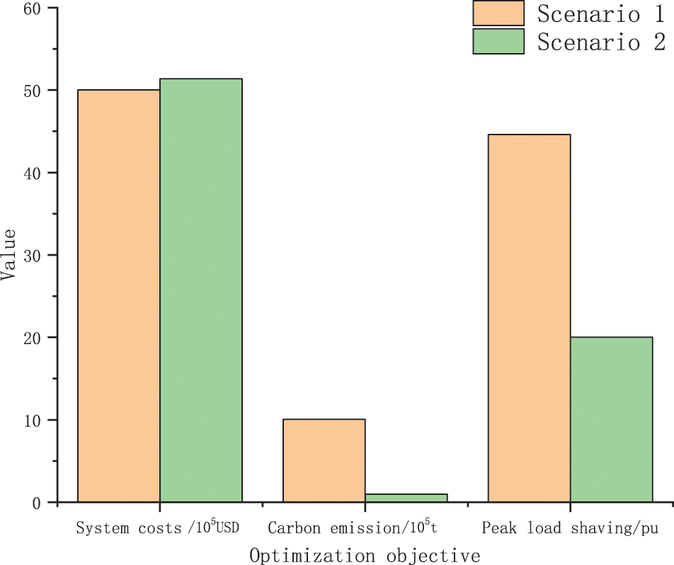
Figure 7: Dispatch rates of wind power and objective values
It can be seen from Fig. 5 that in Scenario 1, the wind farm power is more surplus from 01:00–07:00, and the power load is at a low stage during this period. Therefore, P2G equipment works from 01:00–07:00, which can convert surplus wind energy into natural gas for storage, thereby improving the system’s ability to absorb wind energy. In addition, since the price of natural gas is more expensive than that of coal, gas turbines operate at almost the minimum output and only increase their output at 11:00 during the peak power consumption period to make up for the shortage of power supply for coal-fired units. In Scenario 2, due to the comprehensive consideration of economy, carbon emissions, and peak-shaving and valley-filling, the three target P2G equipment and gas turbines work together to reduce system carbon emissions and smooth the net power load curve, subject to P2G efficiency, additional P2G conversion will increase system operating costs and carbon emissions. Therefore, the injection power of the P2G equipment in Scenario 2 does not change significantly compared with Scenario 1, while the output of gas turbine has a significant change compared with Scenario 1. The increase in gas turbine output can not only significantly reduce the carbon emissions of the system, but also play a role in peak shaving, thereby smoothing the net power load curve of the system. It can be seen from the data in Fig. 7 that in Scenario 2, although the economic target is increased by 2.72% compared to Scenario 1, the remaining carbon emission targets and peak-shaving and valley-filling targets are improved by 8.10% and 55.09%, respectively. The superiority of multi-objective optimal dispatching of the electrical coupling system that takes into account economy, carbon emissions, and peak-to-valley-filling targets.
Based on considering the operation characteristics and constraints of power system and natural gas system, this paper proposes a multi-objective optimization model of electric coupling integrated energy system, which considers economic benefits, environmental benefits, and peak-cutting and valley filling utility, based on electricity to gas technology and gas turbine technology and uses BSO algorithm to solve it. In this paper, the effectiveness of the model is further verified by an example, the results show that compared with the traditional scheduling optimization based on economy, the proposed model can give better play to the comprehensive benefits of the electric-coupling integrated energy system.
Funding Statement: This work was supported by the State Grid Corporation Technology Project (Research and Application of Integrated Energy System Regulation Technology of Power Source, Grid, Load and Storage Interaction (No. SGFJJY00GHJS1900066)).
Conflicts of Interest: The authors declare that they have no conflicts of interest to report regarding the present study.
References
1. Zhou, X. X., Zeng, R., Gao, F., Qu, L. (2017). Development status and prospects of the energy internet. Scientia Sinica (Informationis), 47(2), 149–170. [Google Scholar]
2. Li, K., Zhang, Y. K. (2019). Development situation and opportunities of China’s energy saving market. China’s Energy, 41(12), 28–32. [Google Scholar]
3. Meng, H. (2019). Development status and countermeasures on energy disruptive technologies. Global Science, Technology and Economy Outlook, 34, 71–78. [Google Scholar]
4. Yuan, C. G. (2021). Research on optimal operation and market bidding strategy of electric-gas integrated energy system (Master Thesis). Northeast Electric Power University, China. [Google Scholar]
5. Li, J., Li, X. F., Zhang, N., Zhang, Y., Lv, Q. (2021). An optimal dispatch model of the electricity-heat integrated energy system considering the reserve benefits of the heat storage. Power System Technology, 45(10), 3851–3859. [Google Scholar]
6. Cong, H., Wang, X., Jiang, C. W. (2019). Strategies of optimal operation of integrated energy system in asynchronous market environment. Power System Technology, 43(9), 3110–3120. [Google Scholar]
7. Qiu, B., Zhang, Z. C., Wang, K., Mu, H. B., Yang, Z. (2022). Pressure energy generation of natural gas pipeline considered optimal dispatching research for IES. Power System Technology, 46(4), 1457–1464. DOI 10.13335/j.1000-3673.pst.2021.0557. [Google Scholar] [CrossRef]
8. Cao, B., Lv, G. Y., Wang, N., Jia, D. X. (2021). Research and application of demand response based on optimal scheduling of integrated energy system. Power Demand Side Management, 23(4), 45–50. [Google Scholar]
9. Zhang, T. (2021). Study on coordination and optimization of supply and demand benefits of integrated energy system (Master Thesis). Zhejiang University, China. [Google Scholar]
10. Zhang, J., Fan, H., Zhang, X. J., Dong, Y., Li, M. Y. et al. (2021). Optimal model of cross-regional integrated energy system dispatching considering risk cost. Thermal Power Generation, 2021(8), 121–130. DOI 10.19666/j.rlfd.202104070. [Google Scholar] [CrossRef]
11. Xu, J., Xu, K., Wang, S. J., Li, J., Zhang, X. F. (2021). A multi-energy flow calculation method based on discrete iteration of electricity-gas integrated energy systems. Proceedings of the CSU-EPSA, 34(1), 114–120. DOI 10.19635/j.cnki.csu-epsa.000783. [Google Scholar] [CrossRef]
12. Wang, S. (2021). Reliability evaluation of integrated energy systems considering flexibility on demand side (Ph.D. Thesis). Zhejiang University, China. [Google Scholar]
13. Shuai, X. Y., Wang, X. L., Huang, J. (2021). Optimal configuration of shared energy storage capacity under multiple regional integrated energy systems interconnection. Journal of Global Energy Interconnection, 4(4), 382–392. [Google Scholar]
14. Fang, C., Zhang, Y., Liao, W., Shi, S. S., Liu, D. (2021). Benefit evaluation of energy storage in multi-energy collaborative optimization of regional energy internet. Electric Power Construction, 42(5), 48–56. [Google Scholar]
15. Jiang, Y., Li, X. F., Gao, D. C., Duan, R. Q., Zhou, H. et al. (2021). Combined forecasting of electricity and gas load for regional integrated energy system. Electrical Measurement & Instrumentation. https://kns-cnki-net.webvpn.ncepu.edu.cn/kcms/detail/23.1202.TH.20210429.1059.008.html. [Google Scholar]
16. Zhou, S. C., Guo, Z. X., Cheng, X., Chen, L., Zuo, Z. M. et al. (2021). Planning approach of P2G stations for integrated energy system of electricity-gas interconnection. Guangdong Electric Power, 34(2), 36–44. [Google Scholar]
17. Wang, Y. B., Quan, Z. H., Jing, H. R., Wang, L. C., Zhao, Y. H. (2021). Thermodynamic analysis and operation optimization of multi energy complementary energy storage system. CIESC Journal, 72(5), 2474–2483+2906. [Google Scholar]
18. Qu, J. T. (2020). Analysis of integrated energy system planning based on multi-energy complementation. Electric Engineering, 2020(24), 43–46. [Google Scholar]
19. Chen, Y. (2020). Multi-energy complementary clean energy collaborative optimization scheduling analysis. China New Telecommunications, 22(14), 134–135. [Google Scholar]
20. Yang, Y. P., Duan, L. Q., Du, X. Z., Wang, X. D., Xu, C. (2020). Research foundation and prospect on distributed energy system with the complementation of multiple energy sources. Bulletin of National Natural Science Foundation of China, 34(3), 281–288. [Google Scholar]
21. Wu, Y. L., Fu, Y. L., Li, G. T., Zhang, Y. C. (2020). Many-objective brain storm optimization algorithm. Control Theory & Applications, 37(1), 193–204. [Google Scholar]
22. Guo, Y. N., Jiang, D. Z., Wang, R. R., Gong, D. W. (2021). Structural design of heat exchanger plate with wide-channel based on multi-objective brain storm optimization. Control and Decision. https://kns.cnki.net/kcms/detail/detail.aspx?FileName=KZYC2021070100W&DbName=CAPJ2021. [Google Scholar]
Cite This Article
 Copyright © 2022 The Author(s). Published by Tech Science Press.
This work is licensed under a Creative Commons Attribution 4.0 International License , which permits unrestricted use, distribution, and reproduction in any medium, provided the original work is properly cited.
 Downloads
 Citation Tools