| Energy Engineering |
DOI: 10.32604/ee.2022.019128
ARTICLE
Modeling and Simulation Analysis of Solar Thermal Electric Plants Based on Petri Net
1State Grid Gansu Provincial Electric Power Company Electric Power Research Institute, Gansu Provincial Key Laboratory of New Energy Grid-Connected Operation Control, Lanzhou, 730070, China
2Lanzhou Jiaotong University, Lanzhou, 730070, China
*Corresponding Author: Xiaojuan Lu. Email: luxj@mail.lzjtu.cn
Received: 04 September 2021; Accepted: 12 November 2021
Abstract: At present, solar thermal power generation is in the demonstration stage, and the large-scale production is affected by many factors. In view of the characteristics of different operating modes of photothermal power generation, it is analyzed that the turbine needs to be started and stopped frequently due to different operating modes, which will lead to the instability of the output energy and the reduction of power generation efficiency. In this paper, the dynamic equation of energy conversion process is established by using the law of conservation of energy and conservation of mass. Combined with the logic switching criterion of the system, the system model was established by using the extended differential Petri net, and the validity and accuracy of the model were verified. Through the Petri net model of the system, the system’s working mode switching and power generation situation are analyzed due to the difference of direct normal irradiation intensity (DNI). Finally, the accuracy of the model is proved by comparing it with experimental data of the photovoltaic and thermal demonstration projects that have been connected to the grid.
Keywords: Solar power; hybrid system; petri nets; direct molten salt; mode switch
Due to the increasing demand for the sustainability of energy use, the use of renewable energy has recently attracted interest [1]. Solar thermal power generation has attracted widespread attention because of its energy storage, peak adjustment, and continuous power generation, excellent power quality, and direct access to the grid [2]. At present, the commercial solar thermal power generation projects that have been built in the world are mainly parabolic trough and tower. The two technologies are relatively mature, but the construction cost is difficult. Linear Fresnel technology is relatively new, with simple structure, low construction and operating costs, strong wind and sand resistance, and obvious advantages in Western China. However, due to its long transmission pipeline and direct exposure to the air, the linear Fresnel type solar thermal power generation projects that have been built in the world all use water or thermal oil as the working medium, and the heat storage efficiency is low [3]. At the end of 2019, China completed the world’s first commercial project of molten salt linear Fresnel solar thermal power generation-Dunhuang Fresnel solar thermal project, using binary molten salt as the direct heat transfer and storage medium, the work temperature of molten salt is between 290°C–580°C [4]. Unlike systems that use heat transfer oil as the working fluid, molten salt as a heat transfer fluid allows the system to have a higher heat transfer temperature while reducing the system pressure, resulting in higher thermodynamic efficiency and safety [5].
Hybrid energy system management has always been a major issue in the field of energy engineering. In the field of hybrid batteries, literature [6] proposed an energy management strategy based on adaptive rules to extend the battery life of solar wireless sensor nodes. Literature [7] used a multi-objective optimization algorithm to solve the problem of using retired electric vehicle batteries in the PV-hydrogen-REVB hybrid energy system. Literature [8] proposed an independent hybrid microgrid management system with broad application prospects. Literature [9] proposes to use supercapacitor-battery hybrid energy storage system to extend the cycle life of the battery. The solar thermal power generation system is also a comprehensive energy management system. The difference is that there are very complex energy coupling and conversion relationships in the solar thermal power generation system.
At present, the solar thermal power station with heat storage system that uses molten salt as the heat transfer medium is the main development direction at present, and it is necessary to study the system. Literature [10] combined the thermo-hydrodynamic model of the trough collector with the model of the traditional steam power plant, and established a unified model of the solar power system, but lacked systematic analysis of complex working conditions. Literature [11] verified through experimental tests that compared with other concentrated solar power (CSP) systems, linear Fresnel technology is more suitable for direct molten salt (DMS) heat storage technology, but the current research on CSP systems using DMS is mainly on a certain local module or a certain transient dynamic modeling. Literature [12] used the one-dimensional steady-state distributed parameter model of the collector and uses an object-oriented method to establish the transient model of the parabolic trough collector with molten salt as the heat transfer fluid. Literature [13] established a dynamic model of the CSP system steam power generation system through the lumped parameter method, and simulated the interference that solar thermal electric plants might encounter under variable load conditions. Literature [14] proposed an economic model of solar trough solar thermal power station, which improved the efficiency of solar energy utilization. Literature [15] developed a simulation tool for solar thermal power generation to simulate and analyze the energy conversion process of solar thermal cycle and power cycle respectively. However, the solar thermal power generation system will have different coupling operation modes under different working conditions. In order to achieve the energy conversion and mode switching of the system at the same time, it is necessary to use the modeling method of the hybrid system to realize the hybrid control of the system. Table 1 shows the comparison of related literature and the research content of this article.

Petri net is an important modeling and analysis tool for describing hybrid systems. It can simultaneously describe the control of discrete processes on continuous variables and the dynamic processes of continuous variables. Mixed state Petri nets are widely used in the modeling, analysis and design of temperature control and working condition switching systems. Literature [16] proposed a hybrid petri net model (hybrid state Petri net, HSPN) for process control hybrid system modeling, and designed a hybrid controller based on the HSPN model. Literature [17] established the switching criterion and switching strategy for the large-scale heating process of the electric heating furnace, and realized the accurate and stable switching of the system by using the Petri net model. Literature [18] proposed a hybrid Petri net method to model the system for the scheduling problem of crude oil with different melting points in the refinery, and determine the schedule ability condition by analyzing the dynamic behavior of the network model. Literature [19] proposed a hybrid random timing Petri net for a type of hybrid system, which can simultaneously represent a hybrid system with discrete, continuous, conflict, delay and random characteristics. By establishing an equivalent model of HPN, the advantages of HPN in describing hybrid systems are verified. Literature [20] provided a new hybrid control method based on Petri nets, which combines the existing discrete event system theory and continuous system dynamic theory to model, analyze and synthesize hybrid systems. CSP system has both continuous variables and discrete processes during operation, which is a typical hybrid system [21]. The dynamic equation of the energy conversion process and the logic switching criterion of the mode switching process are established respectively. Based on this, the ex-tended differential Petri net model of the CSP system is established, and the state evolution behavior of the system is analyzed, so as to provide practical engineering for the system using molten salt for heat storage. The above operating program provides a theoretical basis.
2 Analysis of Dynamic Process of Solar Thermal Power Generation System
The energy conversion process of solar thermal power generation system includes solar thermal cycle and power cycle. The solar thermal cycle unit is composed of a concentrated heat collection subsystem and a double-tank heat storage subsystem, which collects and converts solar energy into thermal energy storage; the power cycle is composed of a double-tank heat storage subsystem, a steam generation subsystem, and a power generation subsystem. The stored thermal energy is converted into electrical energy. The continuous part of the Petri net modeling process is realized by the dynamic equation of the energy conversion process.
The heat collecting field focuses the solar energy and heats the molten salt flowing through the heat collecting pipe to convert the solar energy into heat energy. The heat energy absorbed by the heat collecting field is shown in Eq. (1) [22].
where, I is the direct solar radiation intensity, G is the aperture area,
The most significant transient effect in the collector field is the thermal mass of the HTF in the collector tube and pipeline. Therefore, the energy change of the thermal mass needs to be considered when deriving the energy balance equation. Assuming that the incompressible HTF passes through a constant volume heat collection element, its energy balance includes inlet energy
The heat of import and export can be expressed as:
The internal energy term represents the energy change of thermal mass, which can be expressed as:
where,
Substituting Eqs. (3) and (4) into Eq. (2), the partial differential equation of the molten salt temperature at the outlet of the collector field is obtained as shown in Eq. (5).
The heat storage system adopts a double tank model, and uses molten salt sensible heat to store heat. The low-temperature heat storage tank provides liquid molten salt for system operation, and the high-temperature heat storage tank stores heat to ensure the stable power generation of the system. The low-temperature heat storage tank and the high-temperature heat storage tank operate independently, but the same model can be used to simulate the energy conversion process [9].
The mass conservation equation of the thermal storage salt tank is as follows:
where,
In order to prevent the molten salt in the molten salt tank from condensing, the electric accompanying heating method is used to provide supplementary heat to the HTF in the low-temperature heat storage tank. The required heat is calculated based on the volume and temperature of the HTF at the end of the time step, as shown in Eq. (7) shown.
The heat loss model of the low-temperature storage tank is shown in Eq. (8).
where,
The power cycle consists of a dual-tank heat storage subsystem, a steam generation subsystem, and a power generation subsystem. The conversion model from thermal energy to electrical energy is established according to the basic heat transfer equation on the hot side of the heat exchanger, and the thermal energy provided by the high-temperature heat storage tank is shown in Eq. (9).
where,
Assuming that the system provides the same power output during the simulation time, the rated power generation of the system at the design point is P = 50 MW, the conversion efficiency of the known rated cycle is
3 Solar Thermal Power Generation Mode
At present, the technology of solar thermal power generation is developing at a high speed. The operation mode of the system is developing from the direct power generation of heat transfer oil [23] to the direct heat storage of molten salt. The system adopts the direct heat storage of molten salt, and the energy storage system combines the power cycle module with solar energy. The resources are completely decoupled, so that the system can maintain a constant power output in the short transient state of the solar field, so it has better stability and reliability.
Due to the instability of the DNI, the system will have different coupled operation modes under different working conditions. The line Philippine solar thermal power generation system includes anti-condensation protection, heat collection field loop preheating, high temperature heat storage tank heat storage and load Four modes are output. The logic switching between the modes is realized by the switching states of the high and low temperature molten salt pump sets, the bypass valve, the main circuit valve and the external power block. The low-temperature molten salt pump unit pro-vides low-temperature molten salt for the heat collection field and realizes the conversion of solar energy to thermal energy. The high-temperature molten salt pump set provides the required thermal energy for the steam turbine generator set, and realizes the conversion of thermal energy to electrical energy. The external power block heats the heat storage tank to prevent the condensation of molten salt. In each time step, three performance indicators of temperature, mass flow and heat are calculated, and the switching criteria for high and low temperature molten salt pump sets, external power blocks and valve states are set as follows.
• Mode 1: Anti-condensation protection
When closed for a long time or when the temperature is low at night, due to the heat exchange between the tank and the outside, there is an inevitable heat loss, and the heat transfer fluid in the heat storage tank may be cooled to an unacceptably low temperature. In order to avoid this situation, heat insulation and accompanying heating are needed to prevent condensation of the heat transfer medium. The energy conversion process is shown in Fig. 1.

Figure 1: Anti-condensation protection energy conversion process
When
• Mode 2: Preheating of the collector loop
In order to ensure the quality of the high-temperature molten salt in the high-temperature storage tank, the low-temperature molten salt that does not reach the minimum design temperature enters the bypass channel and returns to the low-temperature molten salt tank, and at the same time plays the role of preheating the mirror field. The energy conversion process is shown in Fig. 2.

Figure 2: Circuit preheating energy conversion process
When
• Mode 3: High-temperature heat storage tank heat storage
When the temperature of the molten salt at the outlet of the heat collection field reaches the minimum design temperature of the high temperature storage tank, all the high temperature molten salt output from the heat collection pipeline enters the high temperature storage tank for storage. The energy conversion process is shown in Fig. 3.

Figure 3: Thermal storage energy conversion process
When
• Mode 4: Load output
The heat storage system provides heat energy to the load end according to the output demand of the load end. The energy conversion process is shown in Fig. 4.

Figure 4: Load output energy conversion process
When
The basic principle of FCS-MPC is to first perform online traversal calculations within the sampling period, according to the established system prediction model, to obtain the system output under the combination of each group of switches in the control set, and then establish an evaluation function for comparison, and finally select the order evaluation function. The switch function combination with the smallest value is used as the output signal to act on the inverter.
4 Establish EDPN Model of Solar Thermal Power Generation System
This chapter first defines the extended differential Petri based on the Petri net theory, and then establishes the Petri net model of the system according to the switching conditions.
4.1 Extended Differential Petri Net
Definition 1. The extended differential Petri net is an octet [24],
1. P is a set of limited libraries;
2. T is a finite set of transitions;
3. A is the set of node flow relations, that is, the set of directed arcs
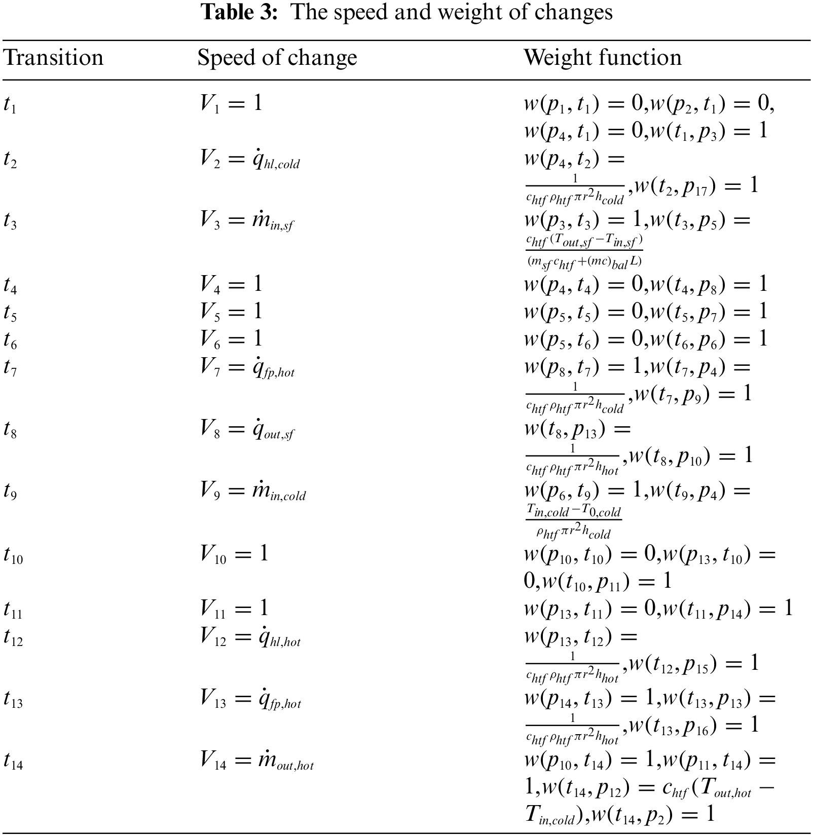
4. W is the generalized weight function matrix of directed arc; its matrix elements are
5.
6. f means
7.
8.
Definition 2. The conditions under which changes occur. In Petri net, the library represents the state of the system, and the change of the system state is described by transition. The Petri net’s network structure is static, and its dynamic characteristics are through the continuous occurrence of discrete events, so that the enabling conditions of change are stimulated, and the conditions for the occurrence of changes are as follows:
1. If
2. If
Definition 3. Evolution rule. The enablement of change leads to the continuous change of the state of the place, which realizes the evolution of Petri net. The transition
1. If
2. If
Definition 4. Net activity [25]. If for any reachable mark
4.2 EDPN Modeling of the System
According to the differential equations of continuous variables and the switching conditions of discrete states, the Petri net model of the solar thermal power generation system is established as shown in Fig. 5. Among them, p3, p6, p7, p8, p13, p16 are discrete places, and p1, p2, p4, p5, p9, p10, p11, p12, p14, p15, p17 and p18 are continuous places. The meaning of the place is shown in Table 2.

Figure 5: Process extended differential Petri net model of solar thermal power generation system

After the system is initialized, it enters the waiting state. When is satisfied
5 Model Verification and Result Analysis
This chapter verifies the reliability of the model by comparing model simulation data with actual experimental data. Then the thermal performance of the system is further analyzed through model simulation.
Through comparison with experimental data, the validity of the Petri net model is verified. Fig. 6 shows the direct solar irradiance received by the solar electric field within a week. Figs. 7 and 8 respectively represent the loop outlet temperature and HTF mass flow rate and relative deviation calculated by the simulation tool and experimental data during the whole week. It can be seen from these charts that the simulation results of the model and the experimental data generally match well. Due to the large fluctuation of DNI on No. 9.17, the relative deviation of temperature reached 10%, but the deviation of cumulative net heat transfer results was less than 1%. It is acceptable for this study. The Petri net model accurately captures the system dynamics in different operating modes, and also ensures continuous conversion between operating modes.
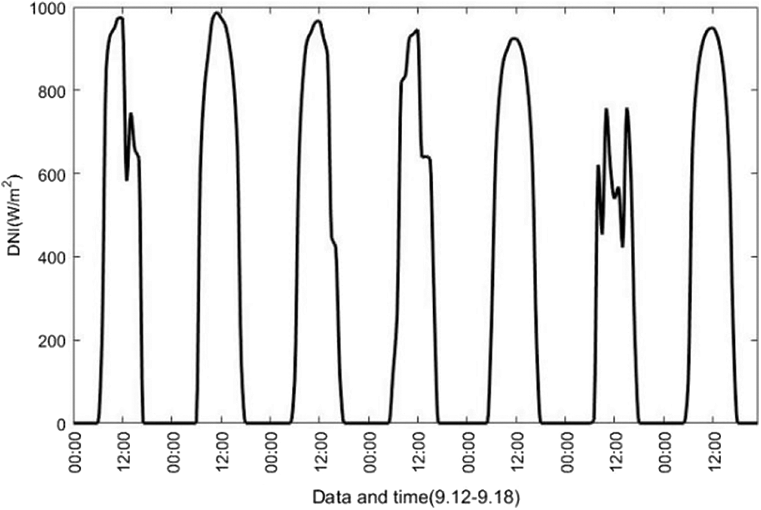
Figure 6: DNI data used in a week of solar farm operation

Figure 7: Comparison of simulated data and experimental data of a solar farm running for a week

Figure 8: Relative deviation between simulated data and experimental data
5.2 Typical Weather Performance Analysis
The Petri net model simulates the thermal energy transfer and mode switching process of the entire factory by considering the solar heat and power cycle of the entire system model. Two days with different irradiance levels were used to simulate and analyze the energy transfer and mode switching of the system, as shown in Figs. 9 and 10. The simulation was carried out for a full 24 h, which is the complete operating cycle of the solar field.

Figure 9: The energy conversion process of a solar power plant on a sunny day. (a) The energy absorbed by the heat collection field, the heat loss of the high and low temperature storage tank, and the mass flow of the heat collection field HTF; (b) High and low temperature heat storage tank HTF inlet temperature and average temperature. (c) High and low temperature heat storage tank HTF level, high temperature heat storage tank output energy. (d) Identification value of discrete changes

Figure 10: The energy conversion process of a solar power plant on a day covered by clouds. (a) The energy absorbed by the heat collection field, the heat loss of the high and low temperature storage tank, and the mass flow of the heat collection field HTF; (b) High and low temperature heat storage tank HTF inlet temperature and average temperature. (c) High and low temperature heat storage tank HTF level, high temperature heat storage tank output energy. (d) Identification value of discrete changes
As shown in Fig. 9, at the beginning of each day, the low-temperature molten salt pump is turned on to output low-temperature molten salt to the heat collection field, and the HTF circulates back to the low-temperature heat storage tank through the heat collection field to preheat the heat collection field. The thermal field gradually warms, the inlet temperature of the collector field rises and the liquid level of the high-temperature storage tank does not change. During this period, the main reflector continues to track the sun (defocus rate = 0%), as shown in Fig. 9 from 6:00 to 17:00 this time. When the allowable inlet temperature of the high-temperature heat storage tank is reached (in this example, it is about 425°C), HTF is circulated to the high-temperature heat storage tank and stores heat, as shown in Fig. 9 from 7:00 to 16:00. As long as the HTF temperature output by the heat collection field reaches the set temperature and the high-temperature salt storage tank is not full, the HTF is completely guided to the high-temperature heat storage tank. Otherwise, the HTF is recycled into the low-temperature heat storage tank, as shown in the two time periods of 6:00 to 7:00 and 16:00 to 17:00 in Fig. 9. The outlet temperature of the heat collection field is maintained at its rated level by controlling the mass flow rate of the HTF. If the DNI exceeds the absorption capacity of the heat collection field, it will be defocused by the main reflector. At the end of the day, when the available DNI is not enough to maintain the minimum operating temperature at the minimum mass flow rate, the HTF mass flow rate is gradually reduced to the minimum value until the DNI is 0, the main mirror is defocused, and the heat collection field begins to slowly cool. During the period from 08:00 to 01:00 the next day, the heat in the high-temperature heat storage tank can meet the output demand of the steam turbine, and the high-temperature molten salt pump is turned on to provide high-temperature molten salt to the steam generator and generate steam to drive the steam turbine unit For power generation, the low-temperature molten salt after heat exchange is recycled to the low-temperature molten salt tank as a reserve of molten salt at the entrance of the heat collection field.
5.3 Typical Annual Thermal Performance Analysis
In order to better evaluate the performance of the solar thermal power generation system, it is necessary to calculate the thermal performance of the system under annual working conditions. Select the local annual irradiance in 2018 as the input data, and the monthly statistics of solar resources are shown in Fig. 11.

Figure 11: Monthly statistics of solar energy resources
Using the typical annual radiation data, the simulated monthly average power generation and cumulative value of the molten salt direct heat storage linear Fresnel power station are shown in Fig. 12, and the total annual power generation is 287.82 GWh. The average annual power generation efficiency is one of the important factors for evaluating the economic performance of solar thermal power plants. The annual power generation efficiency is the ratio of the power generation capacity of the power station in one year to the annual accumulated solar radiation collected, namely:
For solar power plants, the two parts involved in energy conversion are the heat collection subsystem and the power generation subsystem. The heat collection sub-system focuses the solar energy on the surface of the heat collection tube through the main reflector, and then heats the heat transfer flowing through the heat collection tube. The medium realizes the conversion of light energy to heat energy; the power generation subsystem transfers the heat of the high-temperature molten salt to the water vapor through the steam generator, and finally uses the superheated steam to drive the steam turbine unit to realize the conversion of heat energy to electric energy. Using the annual radiation data, the calculated energy absorbed by each energy con-version process is shown in Fig. 13. It can be seen that there is a large amount of energy loss during the photothermal conversion process, and its annual average photo-thermal conversion efficiency is 39.22%. Secondly, the heat loss of the steam turbine generator unit in the thermoelectric conversion process is more, and the average annual thermoelectric conversion efficiency is 40.97%. According to formula 4.8, the thermo electric conversion efficiency of the entire solar thermal power generation system is 16.04%. Therefore, improving the photothermal conversion efficiency and thermoelectric conversion efficiency of the system is an effective measure to improve the photoelectric conversion efficiency of the system, effectively use solar resources, and reduce the cost of electricity. Increasing the heat source temperature can improve the thermo-electric conversion efficiency, but an excessively high operating temperature will reduce the safety and stability of the system. Therefore, improving the light-to-heat conversion efficiency of the collector at an optimal temperature is the main break-through to reduce the cost of solar thermal power stations.

Figure 12: Monthly average power generation

Figure 13: Monthly a energy change of the power station
Using the extended differential Petri net theory to model and analyze the 50 MW line Philippine solar thermal power generation system, compared with other extended forms of the existing Petri net, the extended differential Petri net relaxes the limitation of the arc weight on the triggering conditions, so that the triggering conditions can be defined separately. At the same time, the value type of the arc weight is expanded, the modeling ability of the differential Petri net is improved, and the net model has greater flexibility. focusing on the state evolution behavior of the system, using the state flow simulation tool to visualize the operation process of the system, which is the operation mode of the direct heat storage line Philippine system optimization provides intuitive and powerful tools. The simulation results of the model operation are in line with the expectations of the actual operation, which proves the feasibility and effectiveness of the model. By analyzing the operation modes under two different weather conditions, the results show that the solar thermal power station adopting the molten salt direct heat storage method, because the high temperature molten salt from the collector all enters the high temperature storage tank, and then the high temperature storage tank Input to the steam generator, the process of converting solar energy into heat in the heat collection field and the process of converting heat energy into electric energy by the steam generator do not interfere with each other, which not only protects the steam generator, but also can make short-term mutations in DNI This ensures the stable power generation of the system and avoids the sudden stop of the steam turbine. In order to better evaluate the performance of the solar thermal power generation system, the thermal performance of the system under the annual working conditions is preliminarily estimated. Under the parameters of the molten salt direct heat storage linear Fresnel power station set in this paper, the annual average light-to-heat conversion the efficiency is 39.22%, the average annual thermoelectric conversion efficiency is 40.97%, and the thermoelectric conversion efficiency of the entire solar thermal power generation system is 16.06%. The mirror field accounts for about 1/2 of the total investment. Therefore, the main breakthrough for the reduction of the cost of CSP stations in the future is the improvement of the photothermal conversion efficiency.
Funding Statement: This paper is supported by the Science Technology Project of State Grid Corporation of China (Grant No. 52272219000 V) and the Major Science and Technology Project of Gansu Province (Grant No. 20ZD7GF011).
Conflicts of Interest: The authors declare that they have no conflicts of interest to report regarding the present study.
1. Davarpanah, A., Jamali, D. H., Ahmadi, A., Aliehyaei, M., Ghazanfari, A. (2020). Investigation the integration of heliostat solar receiver to gas and combined cycles by energy, exergy, and economic point of views. Jordan Journal of Applied Science, 10, 5307. DOI 10.3390/app10155307. [Google Scholar] [CrossRef]
2. Fernandez, A. I., Paksoy, H., Kocak, B. (2020). Review on sensible thermal energy storage for industrial solar applications and sustainability aspects. Solar Energy, 209(10), 135–169. DOI 10.1016/j.solener.2020.08.081. [Google Scholar] [CrossRef]
3. Desai, N. B., Bandyopadhyay, S. (2016). Line-focusing concentrating solar collector-based power plants: A review. Clean Technologies & Environmental Policy, 19(1), 1–27. DOI 10.1007/s10098-016-1238-4. [Google Scholar] [CrossRef]
4. Yu, Q., Fu, P., Yang, Y., Qiao, J., Zhang, Q. (2020). Modeling and parametric study of molten salt receiver of concentrating solar power tower plant. Energy, 200(6), 117505–117516. DOI 10.1016/j.energy.2020.117505. [Google Scholar] [CrossRef]
5. Christoph, A. P., Rafael, G., Frank, D., Thomas, M. H. (2019). A Techno-economic comparative analysis of thermal oil and molten salt parabolic trough power plants with molten salt solar towers. AIP Conference Proceedings, vol. 2126, pp. 20014–120023. [Google Scholar]
6. Qi, N., Dai, K., Yi, F., Wang, X., You, Z. et al. (2019). An adaptive energy management strategy to extend battery lifetime of solar powered wireless sensor nodes. IEEE Access, vol. 7, pp. 88289–88300. DOI 10.1109/ACCESS.2019.2919986. [Google Scholar] [CrossRef]
7. Huang, Z., Xie, Z., Zhang, C., Chan, S. H., Milewski, J. et al. (2019). Modeling and multi-objective optimization of a stand-alone PV-hydrogen-retired EV battery hybrid energy system. Energy Conversion and Management, 181, 80–92. DOI 10.1016/j.enconman.2018.11.079. [Google Scholar] [CrossRef]
8. Benlahbib, B., Bouarroudj, N., Mekhilef, S., Abdeldjalil, D., Abdelkrim, T. et al. (2020). Experimental investigation of power management and control of a PV/wind/fuel cell/battery hybrid energy system microgrid. International Journal of Hydrogen Energy, 45(53), 29110–29122. DOI 10.1016/j.ijhydene.2020.07.251. [Google Scholar] [CrossRef]
9. Qi, N., Yin, Y., Dai, K., Wu, C., Wang, X. et al. (2021). Comprehensive optimized hybrid energy storage system for long-life solar-powered wireless sensor network nodes. Applied Energy, 290, 116780. DOI 10.1016/j.apenergy.2021.116780. [Google Scholar] [CrossRef]
10. Odeh, S. D. (2003). Unified model of solar thermal electric generation systems. Renewable Energy, 28(5), 755–767. DOI 10.1016/S0960-1481(02)00044-7. [Google Scholar] [CrossRef]
11. Morin, G., Karl, M., Mertins, M., Selig, M. (2015). Molten salt as a heat transfer fluid in a linear fresnel collector–commercial application backed by demonstration. Energy Procedia, 69(5), 689–698. DOI 10.1016/j.egypro.2015.03.079. [Google Scholar] [CrossRef]
12. Xu, H., Li, Y., Sun, J., Li, L. (2019). Transient model and characteristics of parabolic-trough solar collectors: Molten salt vs. synthetic oil. Solar Energy, 182(4),182–193. DOI 10.1016/j.solener.2019.02.047. [Google Scholar] [CrossRef]
13. Qiang, Z. A., Zw, A., Xdb, A., Gang, Y. A., Hw, C. (2019). Dynamic simulation of steam generation system in solar tower power plant. Renewable Energy, 135(5), 866–876. DOI 10.1016/j.renene.2018.12.064. [Google Scholar] [CrossRef]
14. Alinezhad, K. A., Mohammad, N., Kourosh, J., Mohammadreza, K. (2017). Design of a 25 MWe solar thermal power plant in Iran with using parabolic trough collectors and a two-tank molten salt storage system. International Journal of Photoenergy, 2017(11),1–11. DOI 10.1155/2017/4210184. [Google Scholar] [CrossRef]
15. Bachelier, C., Stieglitz, R. (2017). Design and optimisation of linear fresnel power plants based on the direct molten salt concept. Solar Energy, 152(8),171–192. DOI 10.1016/j.solener.2017.01.060. [Google Scholar] [CrossRef]
16. Engler, F. T. (2005). Design of embedded control systems using hybrid petri nets. Boston, MA: Springer, CiteSeer. [Google Scholar]
17. Xu, B. C., Cai, S. Q., Feng, A. X. (2016). Petri-net based self-prediction and control for switching process of varying duty. CIESC Journal, 67(3), 839–845 (in Chinese). DOI 10.11949/j.issn.0438-1157.20151764. [Google Scholar] [CrossRef]
18. Wu, N. Q., Zhu, M. C., Bai, L. P., Li, Z. W. (2016). Short-term scheduling of crude oil operations in refinery with high-fusion-point oil and two transportation pipelines. Enterprise Information Systems, 10(6), 581–610. DOI 10.1080/17517575.2014.948936. [Google Scholar] [CrossRef]
19. Cao, R. M., Hao, L. N., Wang, F. L., Gao, Q. (2019). Modelling and analysis of hybrid stochastic timed petri net. Journal of Control & Decision, 6(2), 90–110. DOI 10.1080/23307706.2017.1419079. [Google Scholar] [CrossRef]
20. Wan, J., Zhao, B. H. (2019). Hybrid control using cyber net system. Control Theory & Application, 36(9), 1528–1535 (in Chinese). DOI 10.7641/CTA.2019.80539. [Google Scholar] [CrossRef]
21. Kannaiyan, S., Bhartiya, S., Bhushan, M. (2019). Dynamic modeling and simulation of a hybrid solar thermal power plant. Industrial & Engineering Chemistry Research, 58(18), 7531–7550. DOI 10.1021/acs.iecr.8b04730. [Google Scholar] [CrossRef]
22. Elias, T. D. A., Renato, D. C. M. P., Normey-Rico, J. E. (2019). Hybrid predictive controller for overheating prevention of solar collectors. Renewable Energy, 136(6), 535–547. DOI 10.1016/j.renene.2019.01.001. [Google Scholar] [CrossRef]
23. Huang, S. Y., Huang, S. H. (2012). Principles and technologies of solar thermal power generation, 1st ed., pp. 415–456 (in Chinese). Electric Power Press: China, Beijing. [Google Scholar]
24. Cheng, G. P. (2008). Stability analysis and control of several classes of hybrid dynamic systems (in Chinese). Xidian University, China, Xian. [Google Scholar]
25. Liang, X. Z. (2006). Modeling and analyzing the process industry by hybrid petri nets (in Chinese). Beijing University of Chemical Technology, China, Beijing. [Google Scholar]
 | This work is licensed under a Creative Commons Attribution 4.0 International License, which permits unrestricted use, distribution, and reproduction in any medium, provided the original work is properly cited. |