| Energy Engineering |
DOI: 10.32604/ee.2022.018693
ARTICLE
Multifunction Battery Energy Storage System for Distribution Networks
1Department of Electrical Power & Machines, Helwan University, Cairo, Egypt
2Technical Affairs Sectors, South Cairo Electricity Distribution Company, Cairo, Egypt
3Department of Energy Efficiency and Renewables, Egyptian Electric Utility and Customer Protection Regulatory Agency, Cairo, Egypt
*Corresponding Author: Omar H. Abdalla. Email: ohabdalla@ieee.org
Received: 11 August 2022; Accepted: 22 October 2021
Abstract: Battery Energy Storage System (BESS) is one of the potential solutions to increase energy system flexibility, as BESS is well suited to solve many challenges in transmission and distribution networks. Examples of distribution network’s challenges, which affect network performance, are: (i) Load disconnection or technical constraints violation, which may happen during reconfiguration after fault, (ii) Unpredictable power generation change due to Photovoltaic (PV) penetration, (iii) Undesirable PV reverse power, and (iv) Low Load Factor (LF) which may affect electricity price. In this paper, the BESS is used to support distribution networks in reconfiguration after a fault, increasing Photovoltaic (PV) penetration, cutting peak load, and loading valley filling. The paper presents a methodology for BESS optimal locations and sizing considering technical constraints during reconfiguration after a fault and PV power generation changes. For determining the maximum power generation change due to PV, actual power registration of connected PV plants in South Cairo Electricity Distribution Company (SCEDC) was considered for a year. In addition, the paper provides a procedure for distribution network operator to employ the proposed BESS to perform multi functions such as: the ability to absorb PV power surplus, cut peak load and fill load valley for improving network’s performances. The methodology is applied to a modified IEEE 37-node and a real network part consisting of 158 nodes in SCEDC zone. The simulation studies are performed using the DIgSILENT PowerFactory software and DPL programming language. The Mixed Integer Linear Programming optimization technique (MILP) in MATLAB is employed to choose the best locations and sizing of BESS.
Keywords: Battery energy storage system; photovoltaic penetration; peak load reduction; valley filling; MILP optimization
List of Symbols
| CkWh | Paid price for MV customer |
| CSW | Cost of switching one circuit breaker for one time |
| I | Cable current |
| Maximum allowable current for the cable | |
| Ldis | Disconnected load |
| Number of buses | |
| R | Cable resistance |
| SCkWh | Service cost for the medium voltage |
| tr | Reconfiguration time |
| V | Voltage magnitude at bus |
| Number of operating switches during reconfiguration | |
| List of Abbreviations | |
| AD | Anaerobic Digestion |
| BESS | Battery Energy Storage System |
| CART | Classification and Regressive Tree |
| DG | Distributed Generation |
| DPL | DIgSILENT Programming Language |
| EDC | Electricity Distribution Code |
| EgyptERA | Egyptian Electric Utility and Consumer Protection Regulatory Agency |
| EV | Electric Vehicles |
| FIT | Feed-In Tariff |
| I-PV-BESS | Interline-Photovoltaic-Battery Energy Storage System |
| IRENA | International Renewable Energy Agency |
| MDP | Main Distribution Panel |
| MILP | Mixed Integer Linear Programming |
| MSPV | Medium Scale Photovoltaic |
| MV | Medium Voltage |
| PV | Photovoltaic |
| SCEDC | South Cairo Electricity Distribution |
| Wp | Peak Power |
Nowadays, world is moving toward smart and sustainable energy systems. Battery Energy Storage System (BESS) is widely used to achieve this purpose and support energy systems reliability. BESS converts surplus electric energy into stored energy to be used upon demand. Fig. 1 shows the BESS concept, a storage controller and converter grantee the required operation, and energy storage medium to coordinate with any energy storage technology [1].
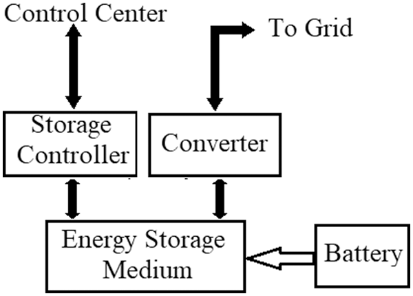
Figure 1: BESS diagram
The International Renewable Energy Agency (IRENA) Report [2] illustrates the contribution of BESS in power system via enabling greater share of renewables with providing grid services. In addition, the report presents BESS in transmission and distribution networks around the world. BESS advantages for distribution networks and its effect on voltage quality are presented in [3]. Distribution losses reduction is the main objective function for optimal location and sizing of BESS as presented in [4–8]. Utilizing BESS as a backup source to supply de-energized zones is a solution to improve network continuity as illustrated in [9]. Optimizing the operational costs and grantee system security by using BESS was introduced in [10]. In [11], improvement of reliability indices was obvious upon integrating BESS into the system, associating them to switching devices for minimizing interruptions. Moreover, BESS is used to avoid feeders’ congestion, voltage deviation, and minimize losses as illustrated in [12]. Peak load periods strain network’s equipment and low load periods decrease equipment’s efficiency. Such inefficient loading affects electricity price. BESS could be used to mitigate the spotted inefficiency via discharge during load peak periods, and recharge during low load periods. Cutting peak load and elimination of new equipment using BESS were presented in [13]. Smoothen uncertainty of PV generation and control active and reactive power flow were the objective function in [14], which used Interline-Photovoltaic-Battery Energy Storage System (I-PV-BESS).
Increasing PV penetration in distribution networks may impact operation due to unpredictable power generation changes, especially if there is no generation prediction tool. Spinning reserves could be used, yet it consumes fuel with no output energy. Another solution is ancillary services, which are series of services needed for maintaining the networks secured and stable. The most significant ancillary services are voltage control, frequency control, generation reserve, and reactive power compensation. BESS could be used as ancillary services as illustrated in [15–18]. BESS could even be adopted as a multifunction for ancillary services such as: mitigating peak loading effects on network’s equipment, increasing efficiency of network’s equipment during low load, a compensation for determined power generation change due to PV, absorbing surplus generation, and improving load factor. Optimization of location and sizing of Distributed Generation (DG) and BESS is a critical issue for improving network operation as voltage profile, losses and cost of energy not supplied. Applying various optimization techniques was the issue discussed by numerous researches [19–21]. For hybrid systems (PV, Anaerobic Digestion (AD), Storage), Lai et al. [22] used solar data collected from Johannesburg, Africa to determine PV sizing and calculate battery capacity to meet the load that cannot be met by PV and AD.
Should it to maintain technical constraints and employ optimal solutions, network reconfiguration is exploited to restore loads after fault. Many researches developed methodologies for minimizing the power losses using optimization techniques as a mixed-integer second-order conic programming [23], and classification and regressive tree (CART) in [24]. In [25], the objective function was to switch actions minimization and maximization of load restoration. Dynamic optimal network reconfiguration was presented in [26] for minimizing power losses, and improving voltage deviation index in present of PV and Electric Vehicles (EV). Optimal location, sizing and operation of DG and distribution network reconfiguration were presented in [27] as to reduce power losses, and in [28] to minimize losses cost and switching cost. The problem arises once the new reconfiguration violates technical constraints. In such a case, BESS can solve the problem and maintain technical constraints with no load disconnection.
This paper presents an Egyptian distribution networks’ structure, sequential steps during fault, and the maximum power change of PV plant based on an actual registration for a year. The paper presents a methodology for optimal location and sizing of BESS to avoid technical constraints violation during reconfiguration after a fault, and compensate unpredictable changes in power generation due to PV plants.
Through the suggested methodology, we propose a procedure for distributed network operator to utilize BESS in PV surplus absorption, peak load cutting, and load valley filling. The DIgSILENT PowerFactory software along with its DPL programming language is employed to adjust the best locations and sizing of BESS. The optimization technique used here is the Mixed Integer Linear Programming (MILP), which is available in MATLAB. The proposed methodology is applied to a modified IEEE 37-node test feeder, and a real network part consisting of 158 nodes in South Cairo Electricity Distribution Company (SCEDC) zone.
The paper is organized as follows: Section 2 presents the proposed methodology for optimal location and sizing of BESS. Section 3 presents the suggested procedure for implementing BESS suggested in the methodology. Section 4 describes the Egyptian distribution network. Section 5 presents case studies modified IEEE 37-node test feeder, and a real network part consisting of 158 nodes in SCEDC zone. Section 6 summaries the main conclusions. Loads and cables length are listed in the Appendixs A and B.
2 Egyptian Distribution Network
This section describes detailed Egyptian network structure, its sequential steps during fault, and technical constraints.
2.1 Distribution Network Structure
Distribution networks are usually composed of many radial type feeders. Each feeder supplies one section in the distributor. The distributor consists of two sections that can be connected to each other via a tie switch. Normally, the distributor has 8–14 outgoing feeders to supply MV loads. The distributor resident technician is responsible for operating circuit breakers; reading every circuit breaker load every hour, inform the control center with circuit break tripping. For more reliability, open cables between MV rooms exist. They are typically used to rearrange the network once a fault occurs. In each MV room, there is a ring main unit consisting of load break switches, a transformer, and a low voltage distribution panel. A part of this network is shown in Fig. 2.
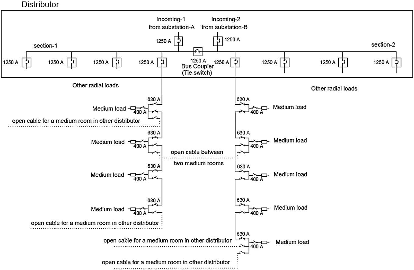
Figure 2: Part of the Egyptian distribution network
2.2 Sequential Steps during Fault
Once a faulty cable arises, its main feeder in the distributor disconnects, such a process is associated with a horn alarm. The resident technician calls the control center informing them with the fault in a certain main feeder. The engineer at the control center shall verify the fault through commanding the technician to reconnect the main feeder. The whole process might approximately take 10 min. Once a real fault is verified, a maintenance technician heads for the nearest MV room, which has an open cable to test its MV cables. In case the faulty cable is determined, it shall be isolated. If not, the technician has to test the other cables in other MV rooms till finding the faulty cable. Finally, the faulty cable is isolated, and the loads will be re-supplied by reconfiguring the network. Every faulty cable may have several scenarios to be used in network reconfiguration. The network operator should select the best scenario that maintains the technical constraints. The network operator can picks up a scenario with the minimum implementation time according to distance, or adopts optimization technique.
1. Medium voltage variation: According to the Electricity Distribution Code (EDC) [29], the licensed distributor shall preserve the limits of the contracted normal voltage at the supply point for the subscriber within ±5% for MV underground network.
2. Maximum cable loading: As per cable manufacturer recommendations for SCEDC, cable loading should be kept less than 0.75 of its rated current due to ambient soil temperature and burial depth [30].
2.4 Actual Records of PV Power Measurement
A Medium Scale PV (MSPV) plant is connected to the MV distribution network according to the Solar Energy Plants Grid Connection Code for connecting medium and large scale PV [31]. Technical requirements for connecting MSPV to Egyptian network are clearly explored in [32]. The MSPV considered here consists of 4488 polycrystalline models with 11 inverters. The technical data of the PV modules and inverters is listed in the Appendix. The inverters’ output was collected to Main Distribution Panel (MDP), then from MDP to a step-up 1.25 MVA transformer for elevating voltage up to 22 kV. Its financial scheme for connection is Feed-In Tariff phase-1 [33]. Feed-In Tariff (FIT) scheme encourages investment in PV since the investor may sell all the PV production with higher tariff than the distribution company’s tariff. Actual MSPV power generation was recorded for a year, and the days with maximum power generation change are illustrated in Fig. 3. The determined power generation change was between 535 kW in 14-3-2019 and 530 kW in 24-10-2019.
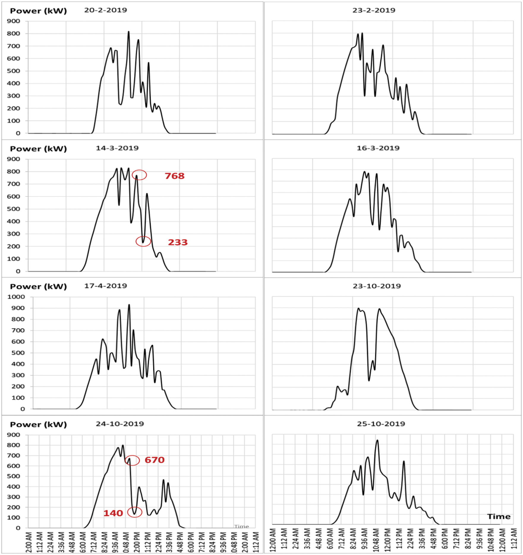
Figure 3: Days with power generation change in a year
3 Proposed Methodology for BESS Sizing and Location
3.1 Network Reconfiguration Shortcomings
Network reconfiguration is used to modify the network topology via opening or closing load beak switches in medium voltage (MV) rooms. Network reconfiguration is an important method for restoring disconnected loads as much as possible after a cable fault. Since many scenarios for reconfiguration may be adopted, the distribution operator should select the lowest cost scenario without violating the technical constraints. In a few cases, none of the available scenarios maintains the technical constraints leading the distribution operator to disconnect loads.
In [34], the objective function of reconfiguration was minimizing the total reconfiguration cost as:
where,
R: Cable resistance
I: Cable current
CkWh: Paid price for MV customer. For 2020/2021 tariff, it is 1.15 LE/kWh
tr: Reconfiguration time
Ldis: Disconnected load
CSW: Cost of switching one circuit breaker for one time
It is possible that none of the available reconfigurations maintain the technical constraint (voltage or loading). Violating voltage may damage customers’ equipment while violating loading constraint may damage network’s equipment. Disconnecting loads was the resolution so as to maintain technical constraints. However, such a solution decreases the revenues of the distribution company. As a better alternative, BESS with optimal location and sizing options could be utilized, rather than disconnecting loads that conflicts utilities regarding the economic considerations.
The methodology comprises five steps as shown in Fig. 4. The steps are as follows:
1. A faulty cable that causes the worst violations of technical constraints is the supplying cable from the outgoing of the distributor to the first Medium Voltage (MV) room. The voltage of this cable will be the lowest voltage in this ring. Additionally, the other cables supplying the addressed MV room shall be overloaded. Therefore, the BESS’s best location should be selected in the first MV room only as technical constraints should be checked for every supplying cable. The DIgSILENT PowerFactory and DPL programming language are used for checking technical constraints. Therefore, the location for BESS is identified.
2. The Mixed Integer Linear Programming (MILP) optimization technique available in the MATLAB is used to determine the optimal BESS capacity to main technical constraint (voltage and loading).
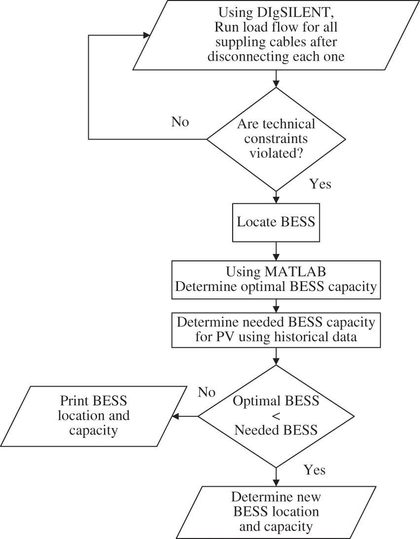
Figure 4: Proposed methodology flow chart
The objective function for improving the voltage profile is:
Constraints for the above objective function are:
where
3. Estimate power generation changes due to PV penetration by using historical data for one year.
4. Compare the optimal BESS size with the needed BESS size to compensate the estimated maximum power generation change.
5. The needed BESS capacity will be distributed with minimum losses constraints using MILP in MATLAB. The objective function is to minimize the losses:
where
4 Proposed Strategy for BESS Scheduling
1. The BESS requires controlled charging and discharging signals as per recommendations of the manufacturer to prevent BESS lifetime reduction due to excessive charging and discharging. For avoiding protection relay malfunction in substation, the PV should not reverse power to the substation. The BESS could absorb all reverse power as charging energy. The distribution operator should compare the load curve (low load day) to PV maximum power curve for determining the reverse power period as charging energy for BESS.
2. For better load factor, the BESS could be charged during low load while discharged during peak load or during PV fluctuations, which leads to network operation enhancement. The Distribution operator shall analyse the load curve for each distributor section using hourly data recorded by resident technician or data from SCADA (if available). Therefore, the distribution operator could determine charging and discharging periods, which should comply with the manufacture’s recommendations.
Two case studies are presented in this section: (i) a modified IEEE 37-node test feeder, and (ii) a part of the real distribution network of the South Cairo Electricity Distribution system. Each case study includes; system description, single-line diagram, network reconfiguration, the proposed methodology for BESS locations and size, along with the suggested procedure for BESS scheduling and simulation results.
5.1 Modified IEEE 37-Node Test Feeder
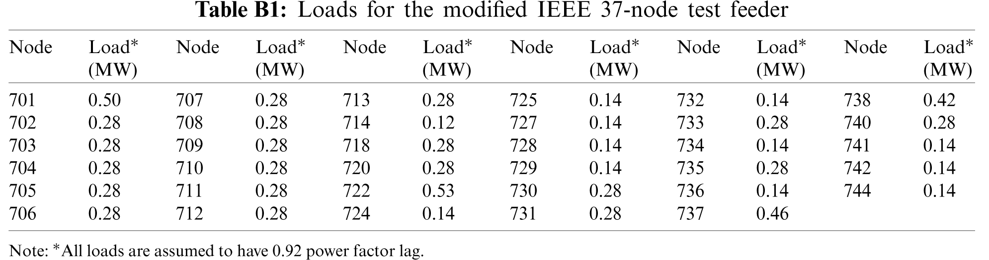
The IEEE 37-node test feeder [35] is modified to be applicable for reconfiguration. As shown in Fig. 5, the modifications are: adding three Medium Scale PV (MSPV) stations, each is 1000 kWp connected according to the IPP scheme; two external grids, 2500 kVA each, 4.8 kV; and two open cables for reconfiguration. The modified elements are shown in red while open cables are presented in dotted red lines. To comply with the MSPV capacity requirements, the IEEE 37-node test feeder loads are modified as listed in Table B1 in Appendix B, and load profile is assumed to be similar to the load profile in [4] with the IEEE 33-bus system.
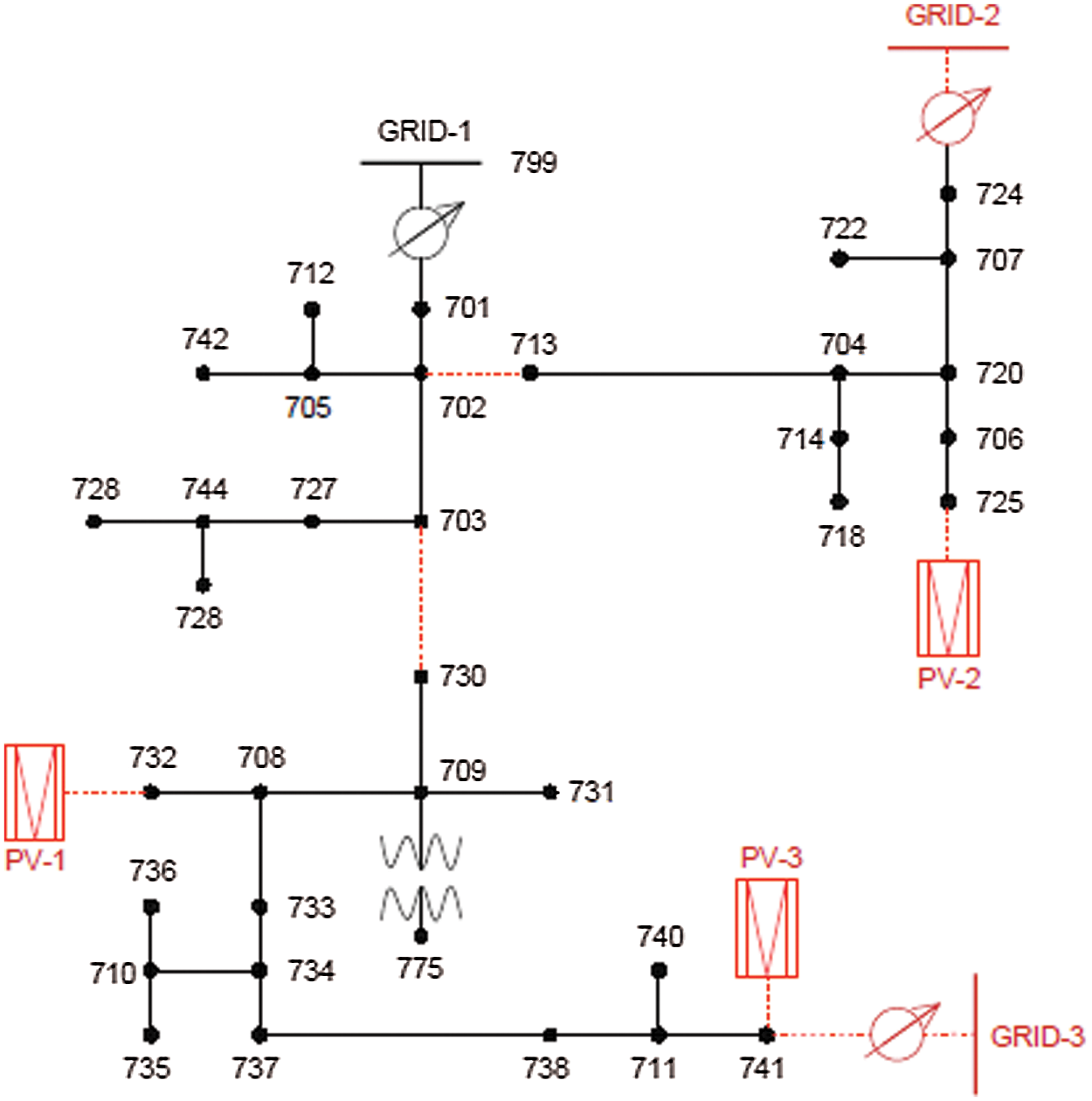
Figure 5: Modified IEEE 37-node test feeder
The suggested scenarios for certain cables (Cables 36, 37, 38) did not maintain the technical constraints, which affected the network performance. Table 1 shows the technical constraints for the modified IEEE 37-node feeder. Bold numbers indicate violation of technical constraints [33].
5.1.3 Proposed Methodology for BESS Location and Sizing
1. Determine technical constraints due to supplying cable disconnection.
Table 1 shows the technical constraints for each cable regarding the available scenarios. For cable-36, 37 and 38, there are many scenarios (some of them are shown). None of these scenarios breaches the technical constraints. The location is initially determined to be the MV room supplying cables with no scenarios to maintain technical constraints.
2. Determine the BESS capacity for selected supplying cables.
For cable-36, 37 and 38, all scenarios violate the technical constraints. Therefore, an alternative is to use a BESS. For selecting the minimum BESS capacity, optimization technique will be used. Table 2 shows the minimum BESS capacities, which maintain the technical constraints.
This network has three PVs with 1 MW capacity each; the needed capacity to compensate the power generation change is 1.6 MW.
5.1.4 Suggested Procedure for BESS Scheduling
1. Fig. 6 shows the distributor load curve and maximum power curve for two MSPVs. No reverse power takes place.
2. To determine the charging and discharging periods, the load curve with two MSPVs is to be utilized. Fig. 7 shows old load curve, new load curve, and BESS charging and discharging capacities. The load factor was 0.87 which will elevate up to 1 after using BESS.
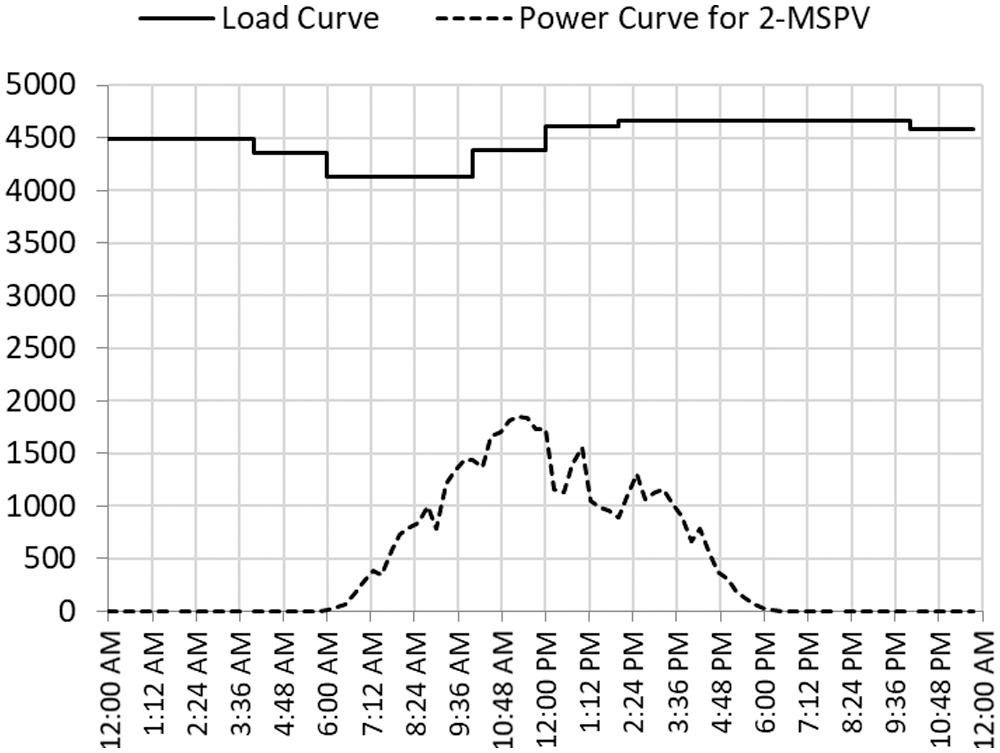
Figure 6: Load curve and maximum power for two MSPVs
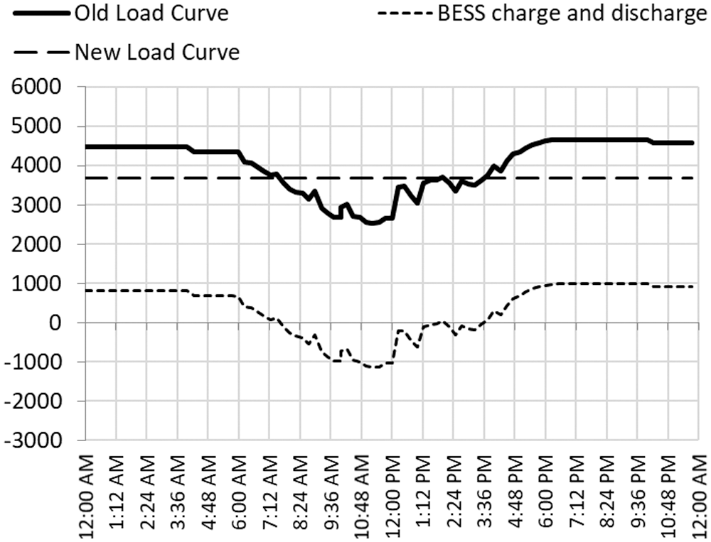
Figure 7: Old & new load curves, and BESS charging/discharging capacities
The BESS will be charged during low load at periods (12 AM: 7 AM) and (6 PM: 12 AM). It will be discharged during PV fluctuations (7 AM: 6 PM).
5.2 Part of a Specific District in SCEDC
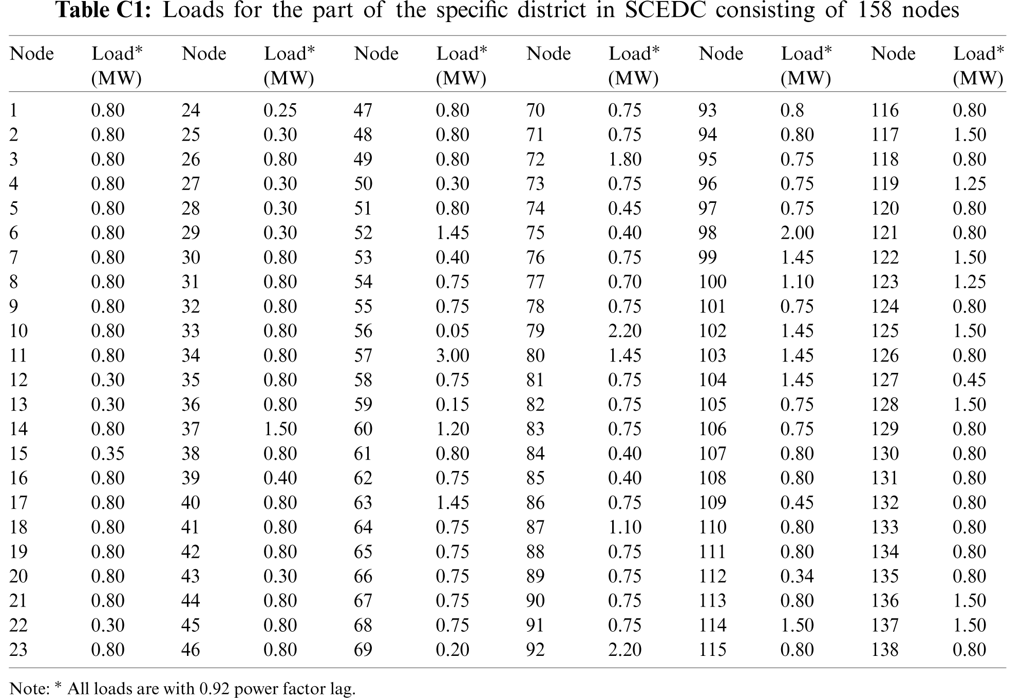
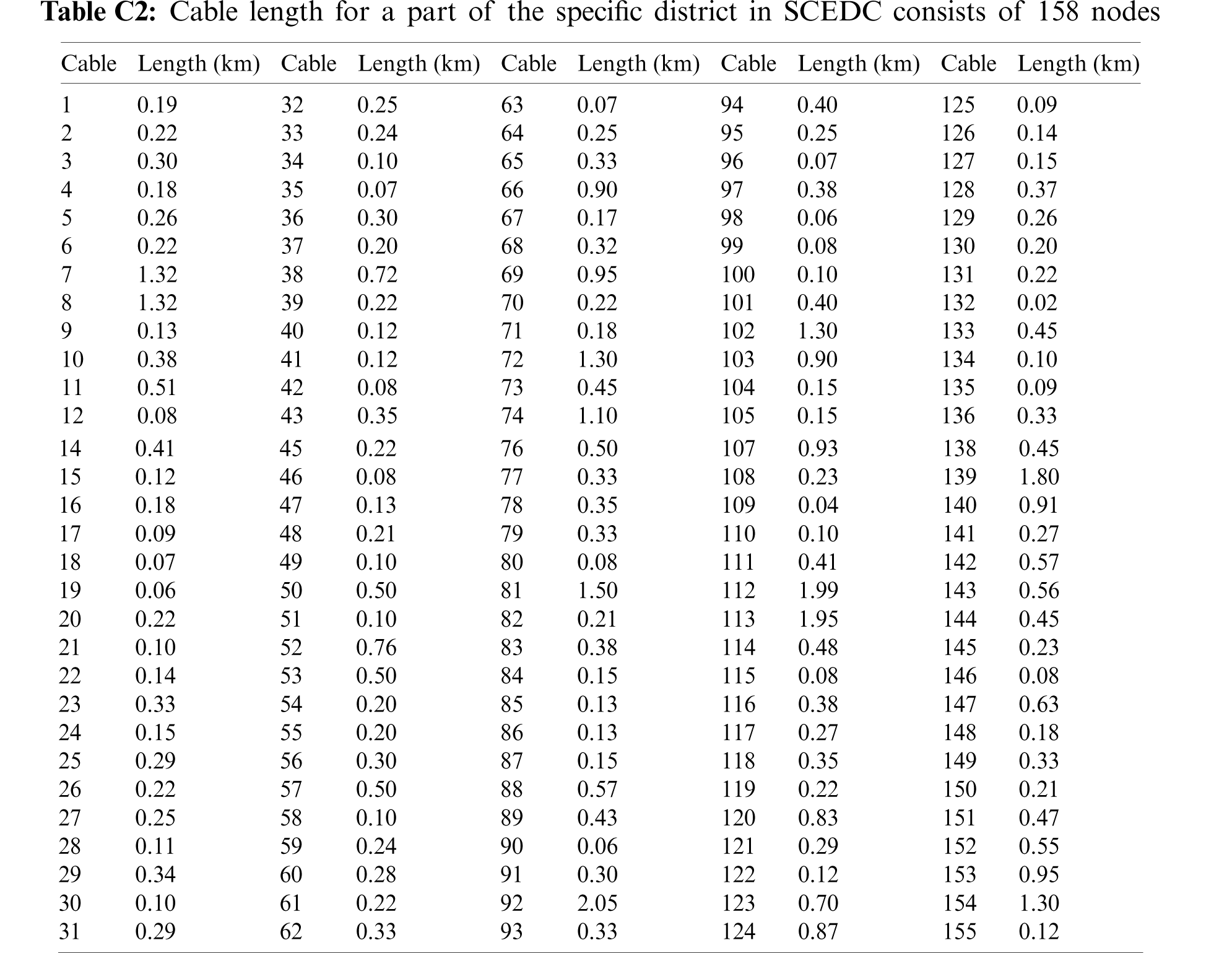
A part of the specific district in SCEDC in Fig. 8 consists of 158 nodes, 138 MV rooms, 155 cables, one MSPV station 1000 kWp connected according to the Feed-In Tariff scheme phase-1 and 17 open cables for reconfiguration. It is supplied from three distributors at 22 kV. All cables are 3 × 240 mm2, 12/20 (24 kV), aluminium, XLPE insulated, steel tape armoured, and PVC sheath as per the distribution company specification. Six MSPV stations are expected to connect according to the IPP schemes, each one 1000 kWp. The expected MSPV are with red colour and open cables are with dotted red lines. Loads and cable length are listed in Tables C1 and C2, respectively, in Appendix C.
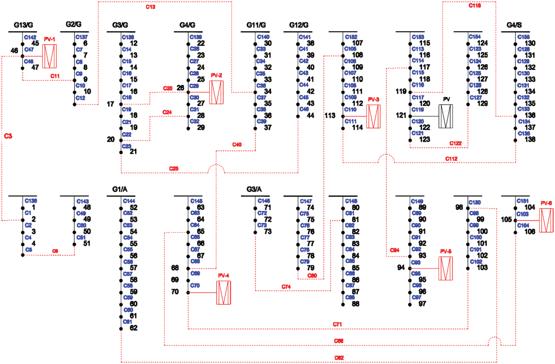
Figure 8: Part of a real network consisting of 158 nodes in SCEDC zone
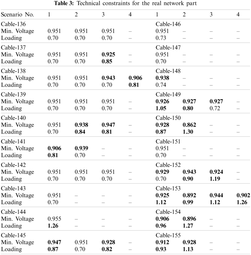
The suggested scenarios for certain cables (Cables 141, 144, 148, 149, 150, 152, 153, 154, 155) did not maintain the technical constraints, which affected the network performance. Table 3 shows the technical constraints for the system. Bold numbers indicate violation of technical constraints [33].
5.2.3 Proposed Methodology for BESS Location and Sizing
1. Determine technical constraints due to supplying cable disconnection.
Table 3 shows the technical constraints for each cable regarding the available scenarios. For Cable-136, there are three scenarios: (Scenario-1 close Cable-3, Scenario-2 close Cable-6 and Scenario-3 open Cable-47 then close both Cable-3 and Cable-11). The location is initially determined to be the MV room supplying cables with no scenario to maintain technical constraints.
2. Determine BESS capacity for selected supplying cables.
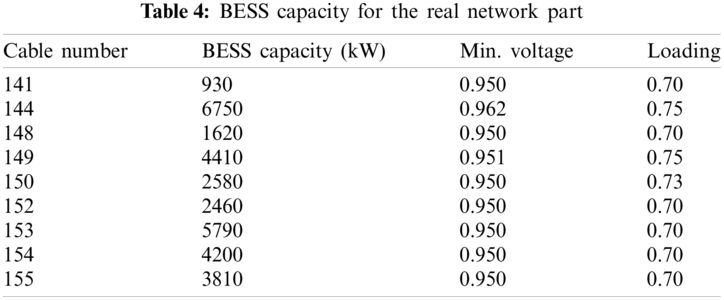
For Cable-141, 144, 148, 149, 150, 152, 153, 154, 155, all scenarios violate the technical constraints. Hence, a resolution is to depend on a BESS. For selecting the minimum BESS capacity, optimization technique is to be implemented. Table 4 shows the minimum BESS capacities, which maintain the technical constraints.
This network has seven PVs with 1 MW capacity each; the required capacity to compensate the power generation change is 3.8 MW. Therefore, there is no need for new BESS to be added.
5.2.4 Suggested Procedure for BESS Scheduling
1. Fig. 9 shows the distributor load curve (low load day) and maximum power curve for two MSPVs. No reverse power occurs.
2. To determine the charging and discharging periods, the load curve with two MSPVs (normal load day) will be used. Fig. 10 shows old load curve, new load curve, and BESS charging and discharging capacities. The load factor was 0.81, which will change into 1 after applying the BESS. The BESS will be charged during low load at periods (12 AM: 7 AM) and (6 PM: 12 AM) whereas it will be discharged at peak load and PV fluctuations (7 AM: 6 PM).
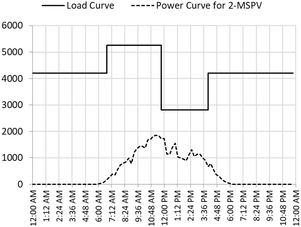
Figure 9: Load curve and maximum power for two MSPVs
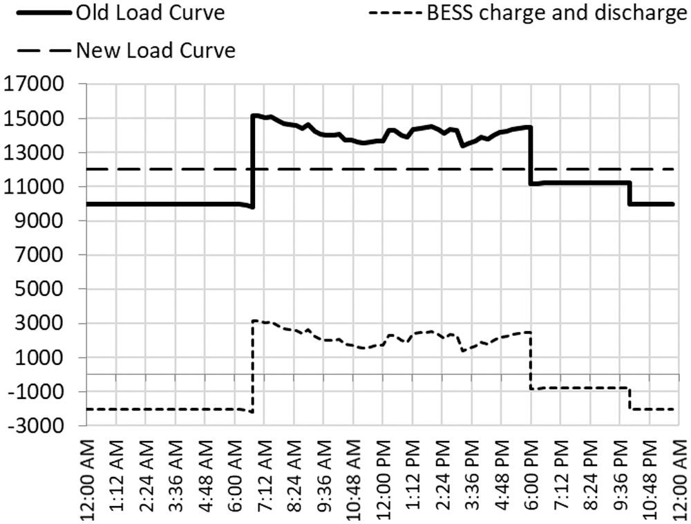
Figure 10: Old & new load curves, and BESS charging/discharging capacities
Along with the distribution networks development and increasing PV penetration, BESS is increasingly becoming a priority for network enhancement. Optimal location and sizing of the BESS are required due to its high cost. The paper has presented the Egyptian distribution networks structure, sequential steps during fault, and the maximum power change of PV plant according to actual registration for a year.
The paper has investigated a methodology for optimum location and sizing of the BESS in order to maintain technical constraints during reconfiguration after a fault, and compensate the unpredictable changes in PV generation power. Additionally, the paper proposed a procedure for distribution network operator to employ the addressed BESS to perform multi functions such as ability to absorb PV power surplus, cut peak load and fill load valley for improving network’s operation. The methodology was applied for two case studies: (i) a modified IEEE 37-node test feeder, and (ii) a part of a real distribution network consisting of 158 nodes in the SCEDC zone.
The methodology suggests the optimum locations and sizing of the required BESS, which results in reconfiguration with no technical constraints, besides compensated PV generation changes. Load factor improvement and PV power surplus absorption were fulfilled via the suggested procedure. DIgSILENT PowerFactory and DPL programming language have been successfully employed in power flow studies. The MILP in MATLAB has been successfully implemented as an optimization technique for selecting the best locations and sizing of the required BESS.
Funding Statement: The authors received no specific funding for this study.
Conflicts of Interest: The authors declare that they have no conflicts of interest to report regarding the present study.
1. Das, C. K., Bass, O., Kothapalli, G., Mahmoud, T. S., Habibi, D. (2018). Overview of energy storage systems in distribution networks: Placement, sizing, operation, and power quality. Renewable and Sustainable Energy Reviews, 91(12), 1205–1230. DOI 10.1016/j.rser.2018.03.068. [Google Scholar] [CrossRef]
2. Utility-Scale Batteries (2019). International Renewable Energy Agency (IRENA) Report. https://www.irena.org//media/Files/IRENA/Agency/Publication/2019/Sep/IRENA_Utility-scale-batteries_2019.pdf. [Google Scholar]
3. Peng, P., Li, Y., Li, Z., Shao, Y., Luo, X. et al. (2018). Analysis of advantage of the connection of energy storage system to distribution network and the impact on the voltage quality. IEEE Conference on Energy Internet and Energy System Integration, pp. 1–9. Beijing. [Google Scholar]
4. Alzahrani, A., Alharthi, H., Khalid, M. (2020). Optimal battery energy storage placement in highly PV—Penetrated distribution networks. IEEE Power & Energy Society Innovative Smart Grid Technologies Conference, pp. 1–5. Washington DC, USA. [Google Scholar]
5. Monteiro, A., Bonaldo, P., da Silva, F.,Bretas, S. (2020). Electric distribution network reconfiguration optimized for PV distributed generation and energy storage. Electric Power Systems Research, 184(3), 106319. DOI 10.1016/j.epsr.2020.106319. [Google Scholar] [CrossRef]
6. Monteiro, R. V. A., Guimarães, G. C., Moura, F. A. M., Albertini, R. M. C., Silva, F. B. (2017). Long-term sizing of lead-acid batteries in order to reduce technical losses on distribution networks: A distributed generation approach. Electric Power Systems Research, 144, 163–174. DOI 10.1016/j.epsr.2016.12.004. [Google Scholar] [CrossRef]
7. Cui, Z., Bai, X., Li, P., Cao, Y., Diao, Z. (2017). Reconfiguration of distribution network based on Jordan frames with energy storage system. IEEE Conference on Energy Internet and Energy System Integration, pp. 1–6. Beijing. [Google Scholar]
8. Bai, K., Yildizbasi, A. (2020). Optimal siting and sizing of battery energy storage system for distribution loss reduction based on meta-heuristics. Journal of Control, Automation and Electrical Systems, 31(6), 1469–1480. DOI 10.1007/s40313-020-00616-6. [Google Scholar] [CrossRef]
9. Akaber, P., Moussa, B., Debbabi, M., Assi, C. (2019). Automated post-failure service restoration in smart grid through network reconfiguration in the presence of energy storage systems. IEEE Systems Journal, 13(3), 3358–3367. DOI 10.1109/JSYST.2019.2892581. [Google Scholar] [CrossRef]
10. Azizivahed, A., Ghavidel, S., Li, L. (2018). A novel energy management in dynamic large scale distribution network reconfiguration integrated by energy storage systems. IEEE Power & Energy Society General Meeting, pp. 1–5. Portland. [Google Scholar]
11. Pombo, A. V., Murta-Pina, J., Pires, V. F.(2017). Multiobjective formulation of the integration of storage systems within distribution networks for improving reliability. Electric Power Systems Research, 148(11), 87–96. DOI 10.1016/j.epsr.2017.03.012. [Google Scholar] [CrossRef]
12. Mukhopadhyay, I., Das, D. (2020). Multi-objective dynamic and static reconfiguration with optimized allocation of PV-DG and battery energy storage system. Renewable and Sustainable Energy Reviews, 124, 109777. DOI 10.1016/j.rser.2020.109777. [Google Scholar] [CrossRef]
13. Abdullah, A., Fahad, A., Nasser, A., Meshal, A. (2020). Assessment of battery storage utilization in distribution feeders. Energy Transitions, 4(1), 101–112. DOI 10.1007/s41825-020-00026-x. [Google Scholar] [CrossRef]
14. Kumar, A., Nand, K., Singh, A. R., Deng, Y., He, X. et al. (2019). Strategic integration of battery energy storage systems with the provision of distributed ancillary services in active distribution systems. Applied Energy, 235(3), 113503. DOI 10.1016/j.apenergy.2019.113503. [Google Scholar] [CrossRef]
15. Varaprasad, J. D., Sreenivasulu, R. (2021). Coyote optimization algorithm for optimal allocation of interline—Photovoltaic battery storage system in islanded electrical distribution network considering EV load penetration. Journal of Energy Storage, 41(4), 102981. DOI 10.1016/j.est.2021.102981. [Google Scholar] [CrossRef]
16. Zheng, Y., Hill, D. J., Dong, Z. Y. (2017). Multi-agent optimal allocation of energy storage systems in distribution systems. IEEE Transactions on Sustainable Energy, 8(4), 1715–1725. DOI 10.1109/TSTE.2017.2705838. [Google Scholar] [CrossRef]
17. Sérgio, F., Santos, D. Z., Fitiwi, M. R. M., Cruz, C. M. P., Cabrita, J. P. S. et al. (2017). Impacts of optimal energy storage deployment and network reconfiguration on renewable integration level in distribution systems. Applied Energy, 185, 44–55. DOI 10.1016/j.apenergy.2016.10.053. [Google Scholar] [CrossRef]
18. Zhao, J. (2018). Optimal real-time scheduling of energy storage systems to accommodate PV generation in distribution networks. In: IEEE innovative smart grid technologies—Asia (ISGT Asia), pp. 1289–1293. Singapore. [Google Scholar]
19. Mehmood, K. K., Khan, S. U., Lee, S., Haider, Z. M., Rafique, M. K. et al. (2019). Optimal sizing and allocation of battery energy storage systems with wind and solar power DGs in a distribution network for voltage regulation considering the lifespan of batteries. IET Renewable Power Generation, 11(10), 1305–1315. DOI 10.1049/iet-rpg.2016.0938. [Google Scholar] [CrossRef]
20. Bineeta, M., Debapriya, D. (2020). Multi-objective dynamic and static reconfiguration with optimized allocation of PV-DG and battery energy storage system. Renewable and Sustainable Energy Reviews, 124, 109777. DOI 10.1016/j.rser.2020.109777. [Google Scholar] [CrossRef]
21. Abou El-Ela, A. A., Ragab, A., El-Seheimy, A., Shaheen, M., Wahbi, W. A. et al. (2021). PV and battery energy storage integration in distribution networks using equilibrium algorithm. Journal of Energy Storage, 42(2), 103041. DOI 10.1016/j.est.2021.103041. [Google Scholar] [CrossRef]
22. Lai, C. S. M., McCulloch, D. (2017). Sizing of stand-alone solar PV and storage system with anaerobic digestion biogas power plants. IEEE Transactions on Industrial Electronics, 64(3), 2112–2121. DOI 10.1109/TIE.2016.2625781. [Google Scholar] [CrossRef]
23. Galat, N. S., Sonawane, P. M. (2017). Distribution system feeder reconfiguration by robust optimization method, objectives and solution methods. International Conference on Intelligent Computing and Control Systems, pp. 248–251. Madurai. [Google Scholar]
24. Gu, S., Xu, S., Han, L., Cheng, S., Zhang, R. et al. (2018). A reconfiguration strategy for active distribution network based on classification and regression tree. 2nd IEEE Conference on Energy Internet and Energy System Integration, pp. 1–5. Beijing. [Google Scholar]
25. Li, J., Ma, X., Liu, C., Schneider, K. (2014). Distribution system restoration with microgrids using spanning tree search. IEEE Transactions on Power Systems, 29(6), 3021–3029. DOI 10.1109/TPWRS.2014.2312424. [Google Scholar] [CrossRef]
26. Pandraju, L., Thandava, K. S., Janamala, V. (2021). Dynamic optimal network reconfiguration under photovoltaic generation and electric vehicle fleet load variability using self-adaptive butterfly optimization algorithm. International Journal of Emerging Electric Power Systems, 22(4), 423–437. DOI 10.1515/ijeeps-2021-0009. [Google Scholar] [CrossRef]
27. Thuan, T. N., Ngoc, A. N., Thanh, L. D. (2021). A novel method based on coyote algorithm for simultaneous network reconfiguration and distribution generation placement. Ain Shams Engineering Journal, 12(1), 665–676. DOI 10.1016/j.asej.2020.06.005. [Google Scholar] [CrossRef]
28. Bagheri, A., Bagheri, M., Lorestani, A. (2021). Optimal reconfiguration and DG integration in distribution networks considering switching actions costs using tabu search algorithm. Journal of Ambient Intelligence and Humanized Computing, 12(7), 7837–7856. DOI 10.1007/s12652-020-02511-z. [Google Scholar] [CrossRef]
29. Egyptian Electric Utility and Consumer Protection and Regulatory Authority (2010). Electricity distribution code. Cairo, Egypt. http://egyptera.org/ar/Download/Code/ElecDisCode.pdf. [Google Scholar]
30. ElSwedy Electric Company. Power cables. http://www.elsewedyelectric.com/Catalogs/Power%20Cables.pdf. [Google Scholar]
31. Egyptian Electric Utility and Consumer Protection and Regulatory Authority (2017). Solar energy plants grid connection code—In addition to the Egyptian transmission grid code and the Egyptian distribution network. Egypt. http://egyptera.org/ar/Download/Code/Egypt_gridcode_for_solar_plant_connectionOnMVandHV.pdf. [Google Scholar]
32. Abdalla, O. H. (2018). Technical requirements for connecting medium and large solar power plants to electricity networks in Egypt. https://www.researchgate.net/publication/325171369_Technical_Requirements_for_Connecting_Medium_and_Large_Solar_Power_Plants_to_Electricity_Networks_in_Egypt/citation/download. [Google Scholar]
33. Cabinet Decree No. 1947/2014. The first round of feed-in tariff mechanism. Cairo, Egypt. http://egyptera.org/Downloads/taka%20gdida/firststage.pdf. [Google Scholar]
34. Abdalla, O. H., Abdel-Salam, G., Mostafa, A. A. (2021). Optimal reconfiguration strategy for distribution networks with PV connected systems. Paper 0286 CIRED 2021 Conference, Geneva, Switzerland. https://www.cired.org. [Google Scholar]
35. IEEE PES, IEEE PES distribution system analysis subcommittee’s distribution test feeder working group distribution test feeders. http://www.ewh.ieee.org/soc/pes/dsacom/testfeeders/index.html. [Google Scholar]
PV module:
YL245P-26b (245 W) polycrystalline,
It consists of 60 cells,
Module dimension = 1.65 m × 0.99 m × 0.04 m,
Module efficiency = 15%,
Electrical specifications at standard test conditions: Maximum Power (Pmax) = 245 Wp,
Maximum Power Voltage (Vmp) = 30.2 V,
Maximum Power Current (Imp) = 8.11 A,
Open-circuit Voltage (Voc) = 37.8 V,
Short-circuit Current (Isc) = 8.63 A,
Temperature coefficients of Pmax = –0.45%/°C.
Inverters:
PVS-100TL (100 kW),
Efficiency = 98.4%,
Electrical specifications:
Maximum power point (MPP) range = 480 V … 850 V, Maximum input current = 6 × 36.0 A,
Power factor range = 0.80 inductive to 0.80 capacitive.
 | This work is licensed under a Creative Commons Attribution 4.0 International License, which permits unrestricted use, distribution, and reproduction in any medium, provided the original work is properly cited. |