| Energy Engineering |
DOI: 10.32604/ee.2022.017988
ARTICLE
Effect of Thermal Conductivity of Tube-Wall on Blow-Off Limit of a Micro-Jet Methane Diffusion Flame
1China Tobacco Hubei Industrial LLC, Wuhan, 430040, China
2School of Energy and Power Engineering, Huazhong University of Science and Technology, Wuhan, 430074, China
*Corresponding Author: Jianlong Wan. Email: jlw@hust.edu.cn
Received: 21 June 2021; Accepted: 16 July 2021
Abstract: The operating range of the flow rate or flow velocity for the micro-jet flame is quite wide, which can be used as the heat source. In order to optimize the micro-jet tube combustor in terms of the solid material, the present paper numerically investigates the impact of thermal conductivity (λs) on the operating limit of micro-jet flame. Unexpectedly, the non-monotonic blow-off limits with the increase of λs is found, and the corresponding generation mechanisms are analyzed in terms of the thermal coupling effect, flow field, and strain effect. At first, the lower preheating temperature of the fuel and larger heat loss amount to the environment lead to a larger blow-off limit at a larger λs. After that, the smaller local flow velocity in the vicinity of flame root and smaller strain effect slightly increase the blow-off limit with the continuously increasing λs. Therefore, it is deduced that the applied performance of micro-jet combustor with a smaller thermal conductivity is better in terms of the blow-off limit.
Keywords: Micro-jet diffusion flame; thermal conductivity; blow-off limit; heat transfer; flow field
As the micro-or mesoscale power sources based on the hydrocarbon fuel combustion have noticeably higher energy densities as compared to the traditional batteries, they are deemed to the promising alternatives for the MEMS [1].
However, two main challenges make the flame hard to keep stable in miniature combustors. The surface area-to-volume ratio sharply increases, which significantly increases the heat losses of the small combustor to the environment [2]. In addition, the residence time in the small combustor is very short, which easily leads to low combustion efficiency [3]. Owing to the above adversities, various unstable flame behaviors (e.g., the spinning or Pelton-wheel-like flames) occur in small combustors [4–9]. Therefore, the flame stabilization in micro- and meso-scale combustion chambers is necessary to be improved by employing various technologies.
For instance, some special configurations (e.g., the Swiss-roll burner and disc-combustor with a radial preheated channel) were employed to decrease the heat loss amount of the combustor and increase the unburned fuel temperature. These heat management methods could significantly improve the micro-scale flame stabilization. It was observed that the heat recirculation effect indeed noticeably expand the operating range of flame stabilization in mesoscale “Swiss-roll” burners [10,11]. A compact disc-combustor with a radial preheated channel was developed to stabilize the micro-scale methane-air flame stability by Wan et al. [12]. The heat recirculation effect also can be remarkably enhanced in the micro combustion chamber with the inserted porous media, so the flame blowout limit can be significantly expended [13–16]. Moreover, the flow recirculation effect induced by the cavity or bluff-body in the miniature combustion chamber is an effective approach to improve the flame stability. It was observed that the operating ranges of the equivalence ratio or inlet flow for the stable flame are quite wide due to the flow recirculation in the micro backward-facing-step tube [17,18]. The recirculation zone induced by the central bluff body [19,20] and cavity [21,22] also could significantly improve the micro-scale premixed flame stabilities, so flame blow-off limits were obviously enlarged. The catalytic segment was also often adopted to improve the micro flame stabilization [23–25]. Chen et al. [24] found that the flammability limit range of the methane-air premixed mixture is extended significantly.
The above reviews mainly focus on the premixed combustion characteristics in small combustors. However, the premixed flame may be flashback at some operating conditions, which is dangerous. Therefore, the micro heat sources based on diffusion flame have attracted much attention. There does not exist flashback for the diffusion flame, and its operating range is wide. The micro-jet diffusion combustion characteristics were studied by some researchers. For instance, Cheng et al. [26] found that the micro-jet hydrogen flame structure is insignificantly influenced by the buoyancy effect. The surrounding natural convection reduced the anchoring ability of micro-jet diffusion flame [27]. A smaller heat-loss and a higher flame temperature due to the heat recirculation of tube-wall is beneficial for anchoring micro-jet diffusion flame location [28,29]. The thermal coupling effect of the micro-jet flame-wall influenced the flame shape and stability [30,31]. It was observed that the non-premixed combustion performance of the micro-jet methane can be improved by adding the hydrogen [32]. Recently, the micro-jet flame blow-off limit achieved an optimal value at the moderate wall thickness [33].
For the practical application, we need to choose a suitable solid material to manufacture the micro-jet tube combustors. As we know, different solid material usually has different thermal conductivity, which influences the thermal expansion effect of gaseous mixture around the tube and the flame-wall thermal interaction. This will affect the flow field and strain rate around the tube. Therefore, this is a complex issue, which has not been systematically studied so far. The present study will investigate the relationship between the wall thermal conductivity and the micro-jet flame blow-off limit. This work not only guides us to reasonably choosing the solid material to fabricate the micro-jet combustor but also extend the understanding of the role of flame-wall thermal coupling effect in determining the micro-jet flame stability.
Fig. 1 demonstrates the physical model of computation domain. It can be seen that the computational zone and the micro jet tube are axial symmetry. In addition, the geometric sizes of the two-dimensional computational zone and micro-jet tube are detailedly demonstrated in Fig. 1.

Figure 1: Physical model of the computation zone and micro-jet tube and the corresponding geometric sizes
Generally, the micro-jet diffusion flame is laminar behavior due to the small Reynolds number Re [30,34], and the maximum Re in the present study is ∼560, so the laminar model was employed here [28–30,34]. Here, a unsteady-state laminar model is also adopted. In addition, the same strategy has been employed to study the micro-jet diffusive combustion characteristics of methane in our previous publications [32,33]. Please refer to our previous publication to obtain the governing equations of the present simulation [33].
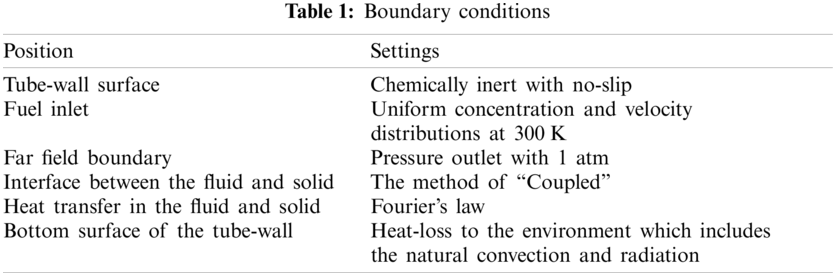
The methane combustion is simulated by the C1 mechanism [35], and the CHEMKIN databases provides the corresponding transport and thermodynamic properties [36]. The thermal conductivity of quartz glass which is adopted to manufacture the micro-jet tube is 2.0 W/(m⋅K) [34]. Five other values, i.e., the values of λs= 200 W/(m⋅K) (copper), 100 (aluminum alloy), 50 (silicon carbide), 25 (stainless-steel), and 0.1 (insulation material) are adopted to study the relationship between the micro-jet flame blow-off limit Bv and the wall thermal conductivity. The software of Fluent 14.0 is adopted to solve the conservation equations [37]. Table 1 displays the computational boundary conditions.
The natural convection coefficient from the bottom surface to the environment is 5.0 W⋅m−2⋅K−1. The grid nodes of the computational domain at the axial direction and radial direction are 210 and 118, respectively. In addition, the strategy of a further refinement of meshes (25 μm) around the fuel outlet is adopted. In addition, the grid-independency has been checked [32]. 1.0 × 10⁻⁸ s is employed as the time-step here [28]. The geometrical model of micro-jet tube and computational methods adopted by the present work are very similar or the same with those in [28,29,31,38]. Gao et al. [28,29] pointed out that the differences between the computational and experimental behaviors and heights of micro-jet diffusion flame are small. Zhang et al. [31] and Li et al. [38] found that the differences between the simulative and measured distribution characteristics of mass fraction of OH (YOH) are also small. Consequently, it is reasonable to have confidence in the computational models/methods adopted by the present study.
The maximum inlet velocity of methane with which the micro-jet diffusion flame can sustain itself is defined as the blow-off limit Bv. Fig. 2 presents a non-monotonic Bv, i.e., with the increase of λs, the Bv sharply decreases first and subsequently increases slightly. The Bv at a moderate thermal conductivity (λs = 50 W/(m⋅K)) reaches the minimum. Next, the cases of λs = 2.0, 50.0, and 100.0 W/(m⋅K) at Vin = 2.0 m/s are employed typically to analysis the mechanism govening the non-monotonic Bv in terms of the thermal coupling effect, the flow filed, and the strain effect.
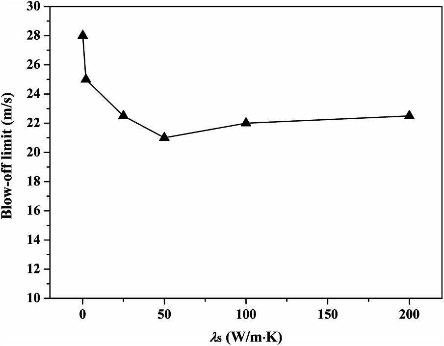
Figure 2: Blow-off limits at various thermal conductivities of tube-wall
Same to our previous publication [39,40] the boundary of flame front is visualized by the 15% maximum isoline of mass fraction of CH YCH here. Moreover, the flame root is defined as the lowest location of flame, and the flame top is defined as the highest location of upstream boundary. As we know, the flame stability is significantly influenced by the flame-wall thermal interaction. At the negative aspect, the flame loses heat to the wall. At the positive aspect, the heat recirculation by the solid wall can well preheat the fresh fuel. Fig. 3 presents the temperature fields overlaid the flame front at various thermal conductivities, which demonstrates that the micro-jet flame significantly heats the solid wall. As a result, the wall temperature is high. In addition, the downstream wall temperature is decreasing with the increase of thermal conductivity mainly owing to a better thermal conduction performance towards upstream. To evaluate the thermal coupling effect quantitatively, the total heat fluxes of the all micro-jet tube walls are displayed in Figs. 4 and 5.
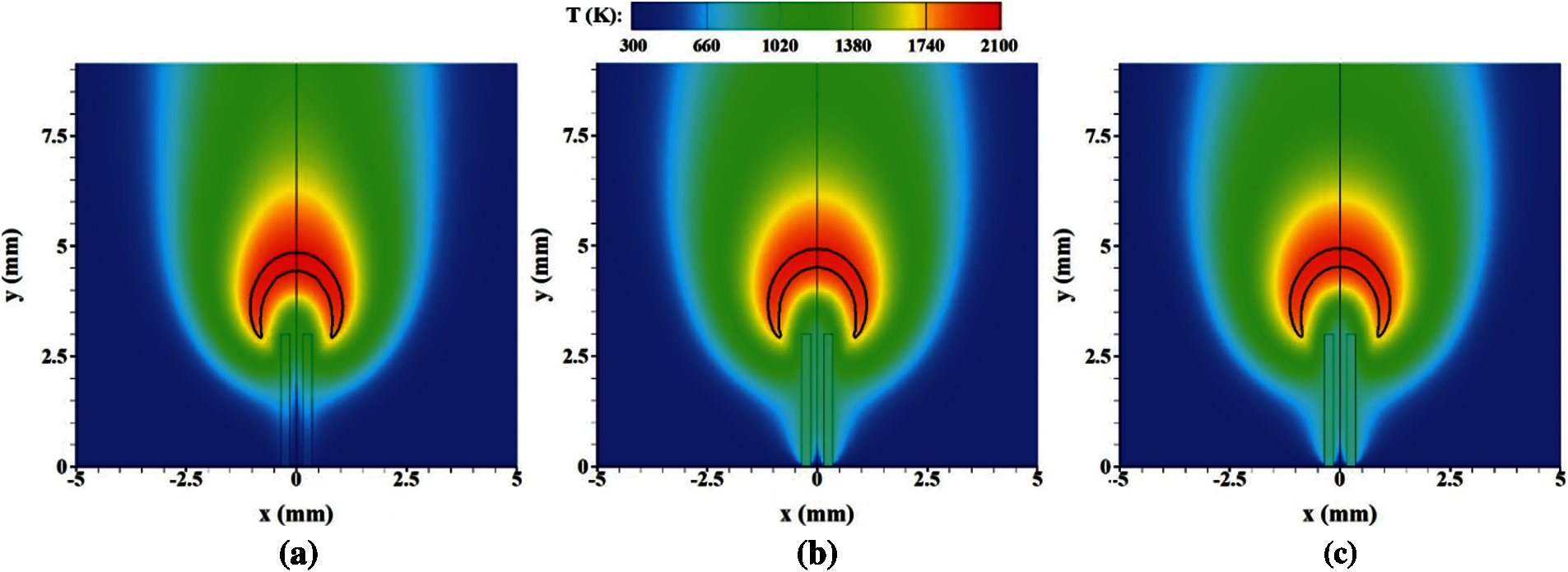
Figure 3: Temperature fields overlaid the flame front at various thermal conductivities of tube-wall. (a) λs = 2.0 W/(m⋅K) (b) λs = 50.0 W/(m⋅K) (c) λs = 100.0 W/(m⋅K)
Fig. 4a demonstrates that the methane is significantly heated by the inner wall. Interestingly, the distribution characteristics of heat flux profiles at λs = 50 and 100 W/(m⋅K) are significantly different with that at λs = 2.0 W/(m⋅K). The maximums of heat flux at λs = 50 and 100 W/(m⋅K) appear at a very upstream location (y ≈ 0.2 mm), and the maximum of heat flux at λs = 2.0 W/(m ⋅ K) appears at a very downstream location (y ≈ 2.6 mm). This means that the fuels at the cases of λs = 50 and 100 W/(m⋅K) are mainly preheated by the upstream inner wall surface, and the fuel at λs = 2.0 W/(m⋅K) is mainly preheated by the downstream inner wall surface. In addition, with an increasing thermal conductivity, the total amount of heat flux is decreasing, which is confirmed by the temperature distribution characteristics of unburned fuel at the exit of tube in Fig. 4b. Fig. 4b indicates that, with an increasing thermal conductivity of tube-wall, the temperature of unburned fuel remarkably decreases, which means a worse heat recirculation effect. The average fuel temperatures at the exit of micro-jet tube at λs = 2.0, 50.0 and 100.0 W/(m⋅K) are 1126.1, 911.3 and 852.4 K, respectively. Furthermore, Fig. 5 indicates that the proportion of recirculating heat in the total absorption of heat (the beneficial part of the absorption of heat) decreases with an increasing λs, which means that the performance of the absorptive heat of solid wall on preheating the fuel for a larger λs is worse. It is known that the flame stability at a lower unburned fuel temperature (i.e., a worse heat recirculation performance) is worse.
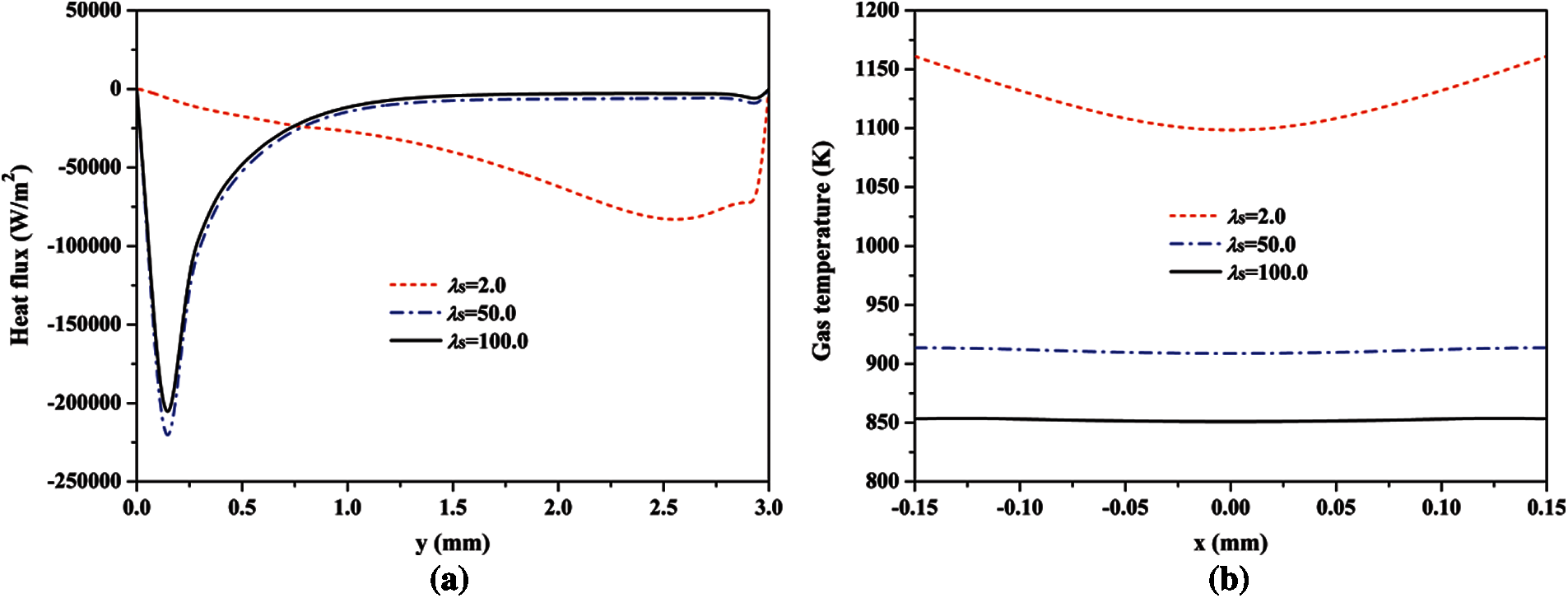
Figure 4: Profiles of the heat flux via the inner wall surface (left figure) and the gas temperature at the exit of micro-jet tube (right figure) at different thermal conductivities of tube-wall (The negative value in Fig. 4a means that the methane is preheated by the solid wall)
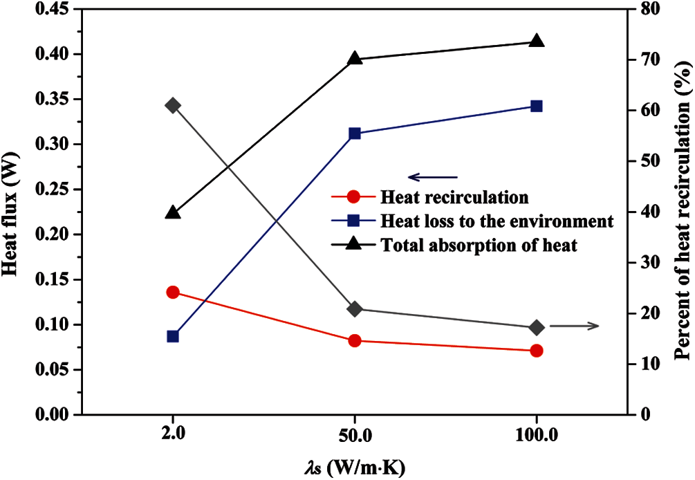
Figure 5: The total heat fluxes of the heat recirculation, heat loss to the environment, and absorptive heat for various thermal conductivities; the proportion of heat recirculation in the total absorptive heat of solid wall at various thermal conductivities
The large absorptive heat of solid wall is detrimental for increasing the flame anchoring ability. Fig. 5 shows that the absorptive heat amount and the heat loss amount to the environment from the solid wall (the difference between the heat flux of heat recirculation and the absorptive heat flux of tube-wall) are both increasing with an increasing λs. The reason is that the thermal conduction performance towards the inlet of micro-jet tube is better for a larger λs.
Therefore, it is deduced that the decrease of Bv from λs = 2.0 to 50 W/(m⋅K) is mainly caused by the worse preheating performance of solid wall and the larger heat loss amount to the environment.
Fig. 6 shows the YCH contours overlaid axial velocity isolines at various thermal conductivities around the exit. It is observed that the recirculation zones next to the micro-jet tube for various thermal conductivities are very small. More importantly, the flame roots are all far away from the recirculation zones, so the flame roots are not anchored by the recirculation zones. Fig. 6 also presents that the flow velocity magnitude is smaller for a larger thermal conductivity. This is probably because that the thermal expansion effect of fuel in the tube is smaller for a larger λs due to the worse preheating effect on the fuel. As a result, the ejecting effect of the high-speed fuel near the exit of micro-jet tube is less obvious, which is confirmed in Fig. 7.
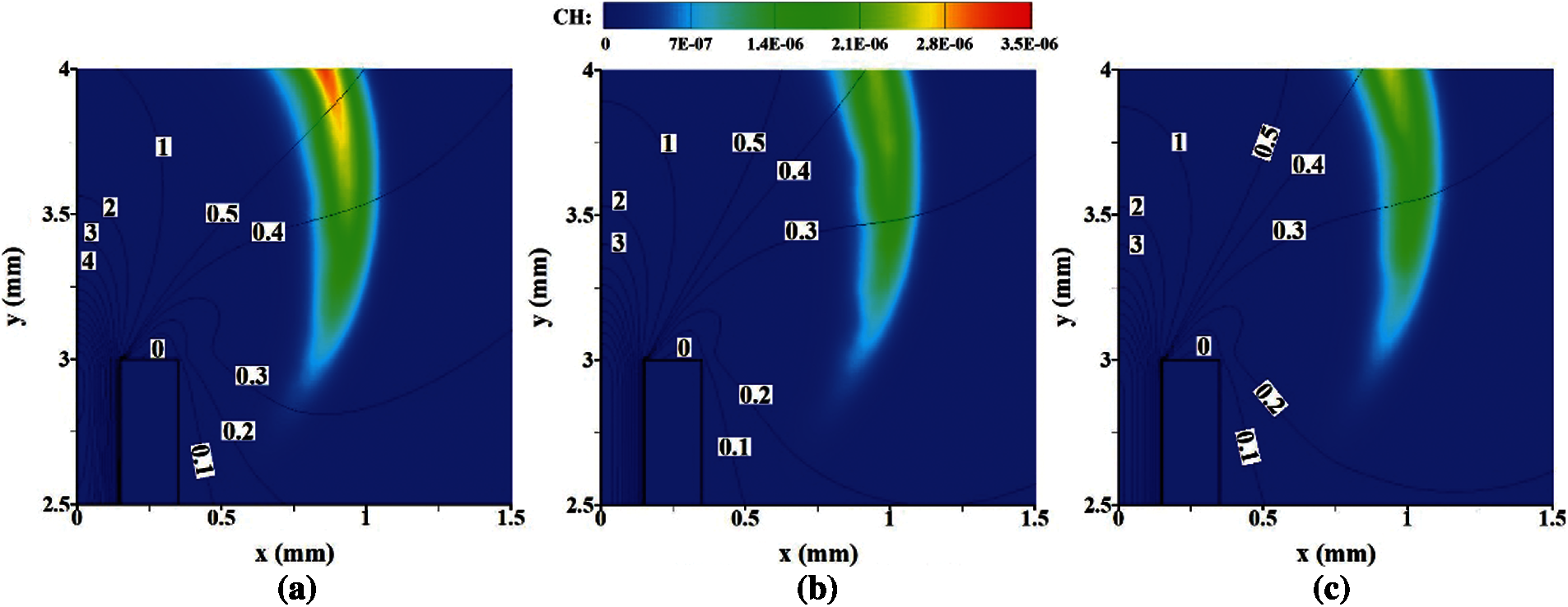
Figure 6: YCH contours overlaid axial velocity (y direction) isolines at various thermal conductivities of solid wall. (a) λs = 2.0 W/(m⋅K) (b) λs = 50.0 W/(m⋅K) (c) λs = 100.0 W/(m⋅K)
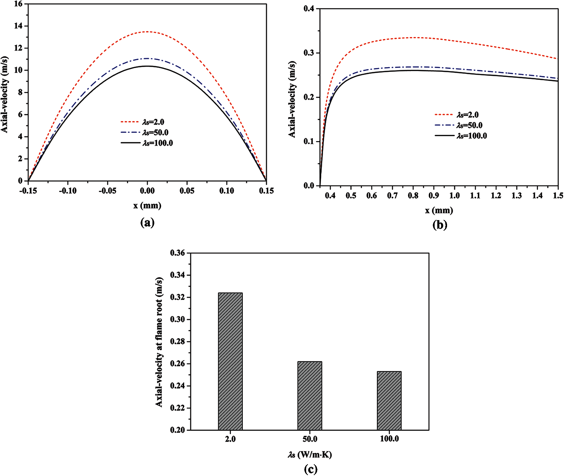
Figure 7: Axial velocity profiles of the fuel at the exit of micro-jet tube (a), axial velocity profiles near the exit of tube at y = 3.0 mm (b), and the flow velocities at the flame root (c) for various thermal conductivities of tube-wall
Fig. 7a presents the axial velocity profiles of the fuel at the outlet of tube, which demonstrates that the axial velocity is smaller in the case of a larger λs. The average axial velocities at the exit of tube in the cases of λs = 2.0, 50.0 and 100.0 W/(m⋅K) are 8.2, 6.7 and 6.3 m/s, respectively. As stated above, a faster axial velocity of fuel can result in a more obvious ejecting effect on the surrounding air (i.e., a faster flow velocity of the gaseous mixture near the fuel outlet). Similarly, Fig. 7b indicates that the flow velocity of the gaseous mixture around the fuel outlet is smaller at a larger λs, and it is calculated that the average axial velocities around the exit of micro-jet tube at λs = 2.0, 50.0 and 100.0 W/(m⋅K) are 0.31, 0.25 and 0.24 m/s, respectively. Therefore, the axial velocity at the flame root decreases with an increasing λs, as presented in Fig. 7c. The axial velocities at the flame root in the cases of λs = 2.0, 50.0 and 100.0 W/(m⋅K) are 0.32, 0.26, and 0.25 m/s, respectively. As we know, the incoming flow can push the flame towards the downstream direction, which is detrimental to the flame root anchoring ability. Thus, it is deduced that a smaller local flow velocity at the flame root contributes to the slight increase of the Bv from λs = 50.0 to 100.0 W/(m⋅K).
The large strain rate is detrimental for the flame stability because it can reduce the local flame speed for the positive Markstein length [41]. Fig. 8 presents the strain rate fields around the micro-jet flame at various thermal conductivities, which indicates that the strain rate around the flame is smaller for a larger λs. Fig. 9 quantitatively displays the distribution characteristics of the strain rate along the upstream boundary at various thermal conductivities of tube-wall, which quantitatively demonstrates that the strain rate is smaller for a larger λs. The average strain rates at the upstream boundary for λs = 2.0, 50.0 and 100.0 W/(m⋅K) are 568, 459 and 445 1/s, respectively. In other words, the strain effect in the case of a larger λs is smaller, which contributes to the micro-jet flame stability. Therefore, the decrease of the strain effect is another factor which slightly increases the blow-off limit from λs = 50.0 to 100.0 W/(m⋅K).
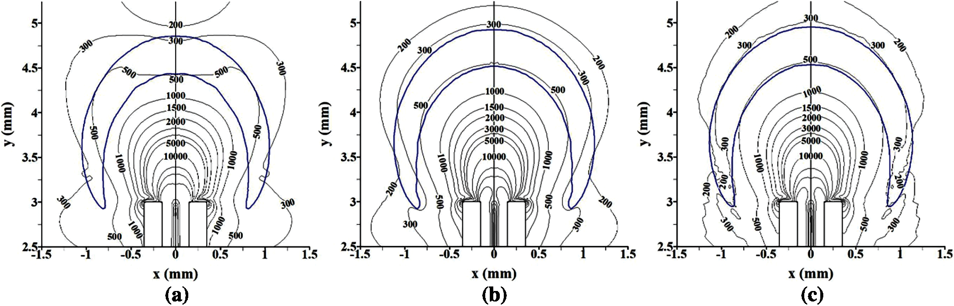
Figure 8: Strain rate isolines overlaid the flame front at various thermal conductivities of tube-wall. (a) λs = 2.0 W/(m⋅K) (b) λs = 50.0 W/(m⋅K) (c) λs = 100.0 W/(m⋅K)
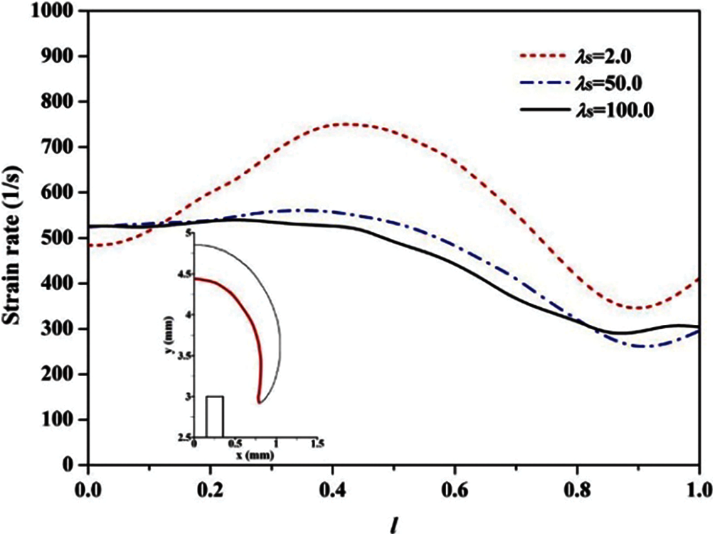
Figure 9: Strain rate along the upstream boundary (the bold red line in the insert) of the flame front at various thermal conductivities. The dimensionless length of the upstream boundary l = lf/lt: lf is the curved distance between the flame top and a given point along the upstream boundary; lt is the length of the upstream boundary)
To provide the guideline for optimizing the solid material which is used to manufacture the micro-jet tube, the impact of wall thermal conductivity on the Bv of the methane diffusion flame is investigated in this study. It is interesting to find that, with the increase of thermal conductivity, the Bv sharply decreases first and subsequently increases slightly, which is the competitive result of the thermal coupling effect, the flow filed, and the strain effect. With the increase of thermal conductivity, the heat recirculation effect is decreasing, but the heat loss amount to the environment and that from the flame to the tube both increase. Furthermore, the flow velocity value at the flame root and the strain effect are both decreasing with an increasing thermal conductivity. Therefore, it is deduced that the larger heat loss amount to the environment and the worse preheating effect of solid wall on the unburned fuel result in the decrease of Bv from λs = 2.0 to 50 W/(m⋅K). The smaller strain effect and local flow velocity at the flame root result in the slight increase of Bv from λs = 50.0 to 100.0 W/(m⋅K). The above results indicate that the micro-jet combustor manufactured by the solid material with a smaller thermal conductivity has a bigger blow-off limit.
Funding Statement: The authors received no specific funding for this study.
Conflicts of Interest: The authors declare that they have no conflicts of interest to report regarding the present study.
1. Ju, Y., Maruta, K. (2011). Microscale combustion: Technology development and fundamental research. Progress in Energy and Combustion Science, 37, 669–715. DOI 10.1016/j.pecs.2011.03.001. [Google Scholar] [CrossRef]
2. Leach, T. T., Cadou, C. P. (2005). The role of structural heat exchange and heat loss in the design of efficient silicon micro-combustors. Proceedings of the Combustion Institute, 30, 2437–2444. DOI 10.1016/j.proci.2004.08.229. [Google Scholar] [CrossRef]
3. Chou, S. K., Yang, W. M., Chua, K. J., Li, J., Zhang, K. L. (2011). Development of micro power generators–A review. Applied Energy, 88, 1–16. DOI 10.1016/j.apenergy.2010.07.010. [Google Scholar] [CrossRef]
4. Maruta, K., Kataoka, T., Kim, N. I., Minaev, S., Fursenko, R. (2005). Characteristics of combustion in a narrow channel with a temperature gradient. Proceedings of the Combustion Institute, 30, 2429–2436. DOI 10.1016/j.proci.2004.08.245. [Google Scholar] [CrossRef]
5. Xu, B., Ju, Y. (2007). Experimental study of spinning combustion in a mesoscale divergent channel. Proceedings of the Combustion Institute, 31, 3285–3292. DOI 10.1016/j.proci.2006.07.241. [Google Scholar] [CrossRef]
6. Kumar, S., Maruta, K., Minaev, S. (2007). On the formation of multiple rotating pelton-like flame structures in radial microchannels with lean methane–air mixtures. Proceedings of the Combustion Institute, 31, 3261–3268. DOI 10.1016/j.proci.2006.07.174. [Google Scholar] [CrossRef]
7. Fan, A. W., Wan, J. L., Maruta, K., Nakamura, H., Yao, H. et al. (2013). Flame dynamics in a heated meso-scale radial channel. Proceedings of the Combustion Institute, 34, 3351–3359. DOI 10.1016/j.proci.2012.06.083. [Google Scholar] [CrossRef]
8. Deshpande, A. A., Kumar, S. (2013). On the formation of spinning flames and combustion completeness for premixed fuel–air mixtures in stepped tube microcombustors. Applied Thermal Engineering, 51, 91–101. DOI 10.1016/j.applthermaleng.2012.09.013. [Google Scholar] [CrossRef]
9. Wan, J. L., Shang, C., Zhao, H. (2018). Dynamics of methane/air premixed flame in a mesoscale diverging combustor with/without a cylindrical flame holder. Fuel, 232, 659–665. DOI 10.1016/j.fuel.2018.06.026. [Google Scholar] [CrossRef]
10. Kuo, C. H., Ronney, P. D. (2007). Numerical modeling of non-adiabatic heat-recirculating combustors. Proceedings of the Combustion Institute, 31, 3277–3284. DOI 10.1016/j.proci.2006.08.082. [Google Scholar] [CrossRef]
11. Wang, S., Yuan, Z., Fan, A. (2019). Experimental investigation on non-premixed CH4/air combustion in a novel miniature Swiss-roll combustor. Chemical Engineering and Processing-Process Intensification, 139, 44–50. DOI 10.1016/j.cep.2019.03.019. [Google Scholar] [CrossRef]
12. Wan, J. L., Zhao, H. (2021). Laminar non-premixed flame patterns in compact micro disc-combustor with annular step and radial preheated channel. Combustion and Flame, 227, 465–480. DOI 10.1016/j.combustflame.2021.01.024. [Google Scholar] [CrossRef]
13. Li, J., Chou, S. K., Li, Z. W., Yang, W. M. (2010). Experimental investigation of porous media combustion in a planar micro-combustor. Fuel, 89, 708–715. DOI 10.1016/j.fuel.2009.06.026. [Google Scholar] [CrossRef]
14. Liu, Y., Fan, A., Yao, H., Liu, W. (2015). Numerical investigation of filtration gas combustion in a mesoscale combustor filled with inert fibrous porous medium. International Journal of Heat and Mass Transfer, 91, 18–26. DOI 10.1016/j.ijheatmasstransfer.2015.07.100. [Google Scholar] [CrossRef]
15. Li, J., Li, Q., Shi, J., Liu, X., Guo, Z. (2016). Numerical study on heat recirculation in a porous micro-combustor. Combustion and Flame, 171, 152–161. DOI 10.1016/j.combustflame.2016.06.007. [Google Scholar] [CrossRef]
16. Li, Q., Li, J., Shi, J., Guo, Z. (2019). Effects of heat transfer on flame stability limits in a planar micro-combustor partially filled with porous medium. Proceedings of the Combustion Institute, 37, 5645–5654. DOI 10.1016/j.proci.2018.06.023. [Google Scholar] [CrossRef]
17. Yang, W. M., Chou, S. K., Shu, C., Li, Z. W., Xue, H. (2002). Combustion in micro-cylindrical combustors with and without a backward facing step. Applied Thermal Engineering, 22, 1777–1787. DOI 10.1016/S1359-4311(02)00113-8. [Google Scholar] [CrossRef]
18. Khandelwal, B., Sahota, G. P. S., Kumar, S. (2010). Investigations into the flame stability limits in a backward step micro scale combustor with premixed methane–air mixtures. Journal of Micromechanics and Microengineering, 20, 095030. DOI 10.1088/0960-1317/20/9/095030. [Google Scholar] [CrossRef]
19. Wan, J. L., Fan, A. W., Maruta, K., Yao, H., Liu, W. (2012). Experimental and numerical investigation on combustion characteristics of premixed hydrogen/air flame in a micro-combustor with a bluff body. International Journal of Hydrogen Energy, 37, 19190–19197. DOI 10.1016/j.ijhydene.2012.09.154. [Google Scholar] [CrossRef]
20. Wan, J. L., Fan, A. W., Yao, H., Liu, W. (2016). Experimental investigation and numerical analysis on the blow-off limits of premixed CH4/air flames in a mesoscale bluff-body combustor. Energy, 113, 193–203. DOI 10.1016/j.energy.2016.07.047. [Google Scholar] [CrossRef]
21. Wan, J. L., Yang, W., Fan, A. W., Liu, Y., Yao, H. et al. (2014). A numerical investigation on combustion characteristics of H2/air mixture in a micro-combustor with wall cavities. International Journal of Hydrogen Energy, 39, 8138–8145 DOI 10.1016/j.ijhydene.2014.03.116. [Google Scholar] [CrossRef]
22. Wan, J. L., Fan, A. W., Liu, Y., Yao, H., Liu, W. et al. (2015). Experimental investigation and numerical analysis on flame stabilization of CH4/air mixture in a mesoscale channel with wall cavities. Combustion and Flame, 162, 1035–1045. DOI 10.1016/j.combustflame.2014.09.024. [Google Scholar] [CrossRef]
23. Ahn, J., Eastwood, C., Sitzki, L., Ronney, P. D. (2005). Gas-phase and catalytic combustion in heat-recirculating burners. Proceedings of the Combustion Institute, 30, 2463–2472. DOI 10.1016/j.proci.2004.08.265. [Google Scholar] [CrossRef]
24. Chen, J., Yan, L., Song, W., Xu, D. (2017). Effect of heat recirculation on the combustion stability of methane-air mixtures in catalytic micro-combustors. Applied Thermal Engineering, 115, 702–714. DOI 10.1016/j.applthermaleng.2017.01.031. [Google Scholar] [CrossRef]
25. Lu, Q., Gou, J., Pan, J., Zhang, Y., Zhu, J., Quaye, E. K. (2019). Comparison of the effect of heat release and products from heterogeneous reaction on homogeneous combustion of H2/O2 mixture in the catalytic micro combustor. International Journal of Hydrogen Energy, 44, 31557–31566. DOI 10.1016/j.ijhydene.2019.10.040. [Google Scholar] [CrossRef]
26. Cheng, T. S., Chao, Y. C., Wu, C. Y., Li, Y. H., Nakamura, Y. et al. (2005). Experimental and numerical investigation of microscale hydrogen diffusion flames. Proceedings of the Combustion Institute, 30, 2489–2497. DOI 10.1016/j.proci.2004.07.025. [Google Scholar] [CrossRef]
27. Nakamura, Y., Yamashita, H., Saito, K. (2006). A numerical study on extinction behaviour of laminar micro-diffusion flames. Combustion Theory and Modelling, 10, 927–938. DOI 10.1080/13647830600941704. [Google Scholar] [CrossRef]
28. Gao, J., Hossain, A., Matsuoka, T., Nakamura, Y. (2017). A numerical study on heat-recirculation assisted combustion for small scale jet diffusion flames at near-extinction condition. Combustion and Flame, 178, 182–194. DOI 10.1016/j.combustflame.2016.12.028. [Google Scholar] [CrossRef]
29. Gao, J., Hossain, A., Nakamura, Y. (2017). Flame base structures of micro-jet hydrogen/methane diffusion flames. Proceedings of the Combustion Institute, 36, 4209–4216. DOI 10.1016/j.proci.2016.08.034. [Google Scholar] [CrossRef]
30. Li, X., Zhang, J., Yang, H., Jiang, L., Wang, X. et al. (2017). Combustion characteristics of non-premixed methane micro-jet flame in coflow air and thermal interaction between flame and micro tube. Applied Thermal Engineering, 112, 296–303. DOI 10.1016/j.applthermaleng.2016.10.082. [Google Scholar] [CrossRef]
31. Zhang, J., Li, X., Yang, H., Jiang, L., Wang, X. et al. (2017). Study on the combustion characteristics of non-premixed hydrogen micro-jet flame and the thermal interaction with solid micro tube. International Journal of Hydrogen Energy, 42, 3853–3862. DOI 10.1016/j.ijhydene.2016.07.255. [Google Scholar] [CrossRef]
32. Li, D., Wang, R., Yang, G., Wan, J. (2021). Effect of hydrogen addition on the structure and stabilization of a micro-jet methane diffusion flame. International Journal of Hydrogen Energy, 46, 5790–5798. DOI 10.1016/j.ijhydene.2020.11.034. [Google Scholar] [CrossRef]
33. Li, D., Liu, B., Huang, L., Liu, L., Ke, W. C. et al. (2020). A non-monotonic blow-off limit of micro-jet methane diffusion flame at different tube-wall thicknesses. Journal of Central South University, 27, 1880–1890. DOI 10.1007/s11771-020-4415-x. [Google Scholar] [CrossRef]
34. Chen, C. P., Chao, Y. C., Cheng, T. S., Chen, G. B., Wu, C. Y. (2007). Structure and stabilization mechanism of a microjet methane diffusion flame near extinction. Proceedings of the Combustion Institute, 31, 3301–3308. DOI 10.1016/j.proci.2006.08.069. [Google Scholar] [CrossRef]
35. Bilger, R. W., Starner, S. H. (1990). On reduced mechanisms for methane air combustion in nonpremixed flames. Combustion and Flame, 80, 135–149. DOI 10.1016/0010-2180(90)90122-8. [Google Scholar] [CrossRef]
36. Kee, R. J., Grcar, J. F., Smooke, M. D., Miller, J. A. (1994). Sandia national laboratories report. SAND85–8240. [Google Scholar]
37. Fluent 14.0 (2011). User's guide. ANSYS Incorporated Company, Canonsburg, PA. [Google Scholar]
38. Li, X., Xie, S., Zhang, J., Zhao, D., Wang, X. (2020). Experimental and numerical study on the quenching limits and mechanism of small-scale H2 diffusion flames. International Journal of Hydrogen Energy, 45, 34281–34291 DOI 10.1016/j.ijhydene.2020.09.124. [Google Scholar] [CrossRef]
39. Wan, J. L., Fan, A. W. (2015). Effect of solid material on the blow-off limit of CH4/air flames in a micro combustor with a plate flame holder and preheating channels. Energy Conversion and Management, 101, 552–560. DOI 10.1016/j.enconman.2015.06.010. [Google Scholar] [CrossRef]
40. Wan, J. L., Fan, A. W., Yao, H. (2016). Effect of the length of a plate flame holder on flame blowout limit in a micro-combustor with preheating channels. Combustion and Flame, 170, 53–62. DOI 10.1016/j.combustflame.2016.05.015. [Google Scholar] [CrossRef]
41. Law, C. K. (2006). Combustion physics. UK: Cambridge University press. [Google Scholar]
 | This work is licensed under a Creative Commons Attribution 4.0 International License, which permits unrestricted use, distribution, and reproduction in any medium, provided the original work is properly cited. |