| Energy Engineering |
DOI: 10.32604/ee.2022.015570
ARTICLE
Protection of Zero-Sequence Power Variation in Mountain Wind Farm Collector Lines Based on Multi-Mode Grounding
1Faculty of Land Resource Engineering, Kunming University of Science and Technology, Kunming, 650093, China
2Faculty of Electric Power Engineering, Kunming University of Science and Technology, Kunming, 650500, China
*Corresponding Author: Yaqi Deng. Email: 20181105001@stu.kust.edu.cn
Received: 28 December 2020; Accepted: 19 February 2021
Abstract: The arc-suppression coil (ASC) in parallel low resistance (LR) multi-mode grounding is adopted in the mountain wind farm to cope with the phenomenon that is misoperation or refusal of zero-sequence protection in LR grounding wind farm. If the fault disappears before LR is put into the system, it is judged as an instantaneous fault; while the fault does not disappear after LR is put into the system, it is judged as a permanent fault; the single-phase grounding fault (SLG) protection criterion based on zero-sequence power variation is proposed to identify the instantaneous-permanent fault. Firstly, the distribution characteristic of zero-sequence voltage (ZSV) and zero-sequence current (ZSC) are analyzed after SLG fault occurs in multi-mode grounding. Then, according to the characteristics that zero-sequence power variation of non-fault collector line is small, while the zero-sequence power variation of fault collector line can reflect the active power component of fault resistance, the protection criterion based on zero-sequence power variation is constructed. The theoretical analysis and simulation results show that the protection criterion can distinguish the property of fault only by using the single terminal information, which has high reliability.
Keywords: Mountain wind farm; multi-mode grounding; collector line; single-phase grounding fault; zero-sequence power variation
Nomenclature
Abbreviations
| SLG: | Single-phase grounding fault |
| ZSC: | Zero-sequence current |
| LVRT: | Low voltage ride through |
| LR: | Low resistance |
| ZSV: | Zero-sequence voltage |
| DFIG: | Doubly-fed induction generator |
| ASC: | Arc-suppression coil |
With the increase of the global environmental crisis and the reduction of traditional energy sources, wind power generation has attracted significant attention. Wind power generation has penetrated the power grid, which the internal fault may pose a threat to the operation of the power grid [1–5]. In recent years, large amounts of mountain wind farm have been built in China considering the abundant wind energy resources in mountain, while the particularity is determined by the geographical environment [6–8]. The collector lines of the mountain wind farm are hybrid consisted of overhead line and cable [9,10]. Due to the influence of thunderstorm weather, the fault rate of the mountain wind farm is high [11,12], which SLG accounts for 80%, and most of them are instantaneous fault. If the arc-suppression coil (ASC) grounding mode is adopted, the recovery speed of the fault phase voltage can be reduced, and the instantaneous fault can be eliminated [13]. If the low resistance (LR) grounding mode is utilized, fault current increases, and characteristics of fault are obvious [14], which can improve the reliability of protection operation as a high-impedance fault. To prevent the fault from expanding, the fault should be removed rapidly [15,16].
At present, the conventional three-section current protection is still applied to the collector line [17]. When collector lines appear fault, the wind turbine is regarded as the load, which the influence of output-characteristics of the wind turbine on the protective operation is not considered [18,19]. Scholars have carried out a lot of research on the protection in collector lines of wind farm. The voltage at the end of the doubly-fed induction generator (DFIG) will drop deeply after short-circuit fault in the collector line. To protect the rotor converter, crowbar protection is connected that can provide a path for the rotor current to realize low voltage ride through (LVRT) [20–23]. Due to the crowbar protection operation, the current sampled by the protective device is not at the level of power frequency, its frequency range is 35–65 Hz [24], which causes the performance of traditional power frequency current protection to decrease. The synchronous voltage and current are sampled by real-time communication and the impedance is calculated to protect the collector line in [25], while the algorithm is highly dependent on the communication system. The stator current of DFIG under short-circuit fault are deduced in [26], and the variation law of steady-state power frequency alternative current component amplitude of DFIG fault current with the voltage-sag degree and crowbar resistance is revealed. However, only crowbar input is considered for the above-said scheme. By analysing the characteristics of current and voltage of the collector line after fault [27], the equation of voltage drop is constructed and the adaptive coefficient is calculated to form new adaptive distance protection. The setting and configuration of protection on DFIG wind farm with LVRT are discussed in [28], it pointed out that LVRT may cause protection device to refuse to operate, which explained the necessity of coordination both current protection in collector line and LVRT, whereas specific scheme was not elaborated. The protection of the collector line has the problems of high sensitivity and lower selectivity, which cannot coordinate with LVRT. Based on the study of short-circuit current characteristics of wind turbine and collector line of wind farm considering LVRT, a new collector line protection setting scheme combined with LVRT is proposed in [29]. Nevertheless, the protection is affected by the control strategy of LVRT. By referring to the current differential principle with considering various operation conditions, an adaptive differential protection algorithm for wind farm has been introduced in [30], while the method is only applicable to SLG. The above literature does not consider the change of fault characteristics under various grounding modes. If the fault cannot recover quickly or the protection cannot remove the fault in time after the short-circuit fault or SLG occurs in the collector line, and the wind turbine may face a risk of off-grid, which is quite distinct from the distribution network with reclosing. Combined with the merits of ASC grounding and LR grounding, ASC in parallel with LR grounding in multi-mode grounding mode is utilized in mountain wind farm [31]. The multi-mode grounding mode enables the collector lines to extinguish the arc quickly as an instantaneous fault occurs, while make the protection device operate reliably in case of a permanent fault.
This paper analyzes the distribution of zero-sequence voltage (ZSV) and zero-sequence current (ZSC) after a single-phase grounding fault (SLG) appears in the collector line of multi-mode grounding mode. Based on the analysis of ZSV and ZSC, the zero-sequence power variation of non-fault collector line is small, while the zero-sequence power variation of fault collector line can reflect the active power component of fault resistance. The zero-sequence power of collector line is constructed as the characteristic quantity of SLG identification of wind farm. The protection principle is verified by simulation that can distinguish the property of fault only by using the single terminal information with voltage and current, which has high reliability.
The remaining of this paper is organized as follows: Section 2 is devoted to analyzing the characteristics of ZSV and ZSC after SLG occurs in ASC grounding and multi-mode grounding. In Section 3, due to the characteristics of zero-sequence power variation in fault collector line and non-fault collector line, the protection criterion based on zero-sequence power variation is proposed and the threshold value of protection is set. In Section 4, the reliability of the proposed protection is verified by simulation considering different collector line, different fault distance, and fault inception time. At last, some conclusions are summarized in Section 5.
2 Characteristics of ZSV and ZSC under Grounding Fault
2.1 Grounding Mode of Main Transformer in Wind Farm
Overhead line and cable are connected to mountain wind power. After a SLG occurs in the collector line, the overhead line always belongs to an instantaneous SLG, while the cable tends to appear permanent SLG accompanied by the higher capacitive current. The multi-mode grounding can weaken the recovery speed of fault phase voltage, which is the benefit to instantaneous SLG disappearance; LR is connected after a high-impedance fault or permanent SLG appears in the collector line, which can make ZSC increase and characteristics of fault obviously and that is conducive to improve the reliability of protection action. The following research will focus on the analysis of SLG that occurs in the collector lines of the mountain wind farm, the equivalent system diagram is shown in Fig. 1.
2.2 Characteristic Analysis of Zero-Sequence Component under Grounding Fault
2.2.1 Zero-Sequence Component Grounded by ASC
As a SLG occurs in collector line L1, the damping resistance is exited by the system and L of ASC is put into. The equivalent zero-sequence network of SLG in the collector line is shown in Fig. 2. In Fig. 2, where Rd is the fault resistance, R denotes damping resistance of ASC and the leakage resistance of line, Rn expresses the resistance of neutral point, C means the sum of capacitance to ground of line, UA0 = −EA, EA represents fault phase voltage.
As ASC is connected, ZSV is defined as follows:
The fault current is
The ZSC is as follows:
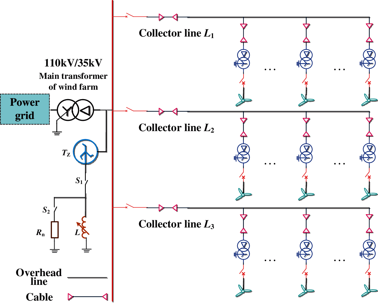
Figure 1: Typical wind farm equivalent system diagram
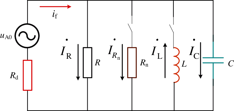
Figure 2: The equivalent zero-sequence network diagram of SLG under different grounding modes
2.2.2 Zero-Sequence Component of Multi-Mode Grounding
If the zero-sequence power can still be detected after ASC is connected with a certain time delay, LR is put into and then the grounding mode is changed into the multi-mode grounding. The leakage resistance is higher than the resistance of neutral point Rn, it can be approximately equivalent to Rn that R and Rn are in parallel. ZSV can be expressed as
The fault current is
The ZSC is as follows:
From Eqs. (4)–(6), it can be shown that ZSV decreases and ZSC increases after LR is connected, while the active power component increases gradually.
To reduce the wind turbine off-grid caused by the fault, the multi-mode grounding is adopted in the mountain wind farm. ASC is connected to clear the instantaneous SLG; while LR is connected after a permanent SLG appears, it can increase the fault current and make the protection device operate reliably.
3 Criterion of SLG Protection Based on Zero-Sequence Power Variation
3.1 Construction of Protection Characteristic Quantity
According to the characteristics of ZSV and ZSC, the zero-sequence power [32] of each collector line after fault is established by
where Pb denotes zero-sequence power of each collector line under normal conditions; Pf means zero-sequence power of each collector line after the fault. The zero-sequence power variation of each collector line in case of SLG is
Due to ZSV and ZSC of the fault collector line contains the zero-sequence component generated by the fault resistance, which the zero-sequence power variation
3.2 Protection Criterion and Setting Principle
From the analysis of 3.1, the zero-sequence power variation of the collector line is greater than the non-fault collector line. Therefore, the criterion of SLG protection based on zero-sequence power variation is constructed as follows:
where
The protection device should avoid possible unbalance condition, and the threshold value of protection can be set with a certain margin. It is appropriate to set the threshold value to 7.5 kW with considering the reliability of the protection operation.
Combined with the merits of the multi-mode grounding, zero-sequence power variation as the characteristic quantity of protection criterion is applied to mountain wind farm that can accurately differentiate instantaneous-permanent fault. The procedure of the proposed protection method is as follows:
Step 1: ZSV and ZSC after fault are obtained, and the zero-sequence power variation of each collector line is calculated;
Step 2: If the zero-sequence power variation
Step 3: LR is connected after the zero-sequence power variation
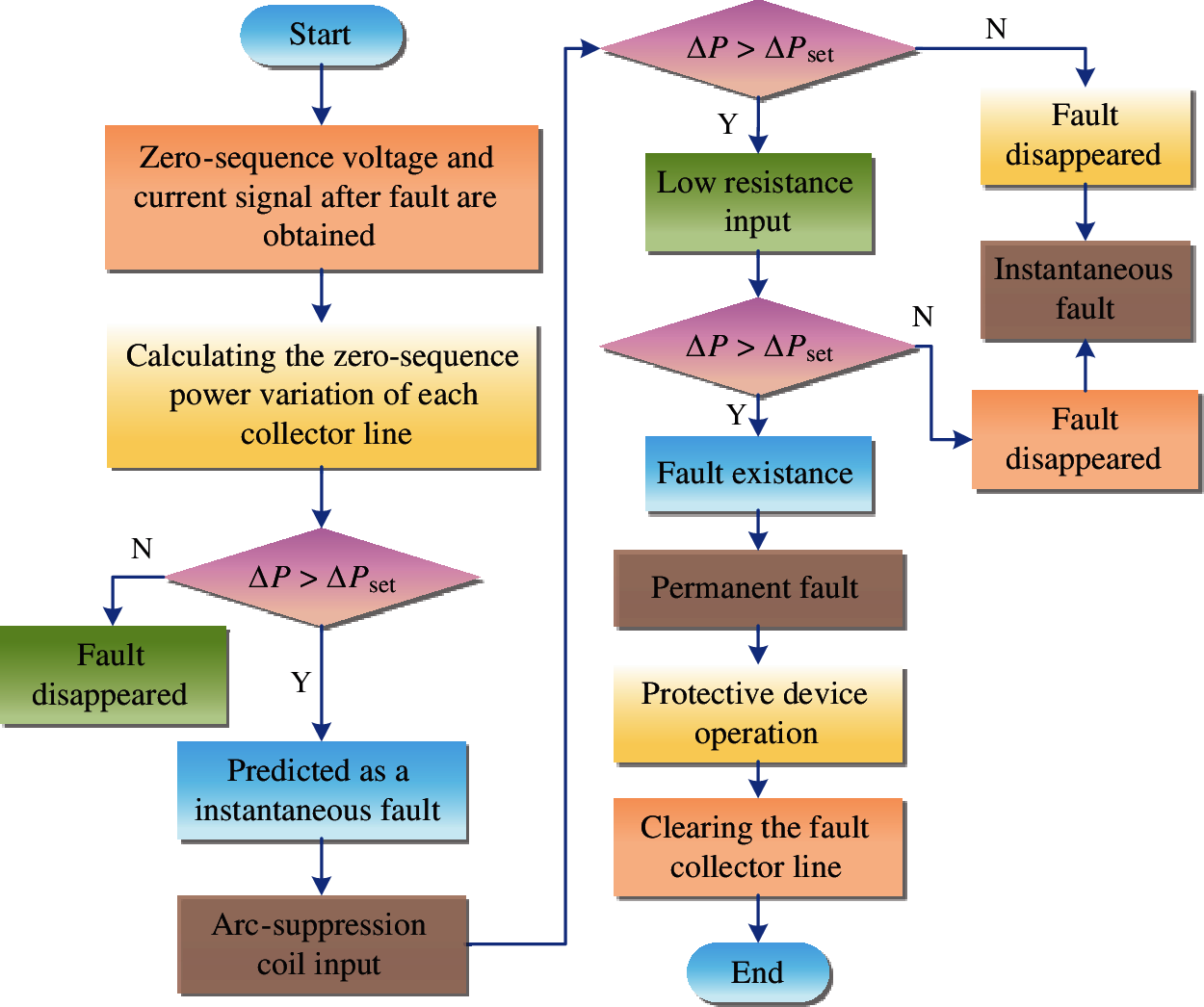
Figure 3: Flowchart of protective operation
4 Analysis and Verification of Simulation
4.1 Construction of Simulation Model
The multi-mode grounding mountain wind farm simulation is established by PSCAD, as shown in Fig. 4. The main transformer capacity of the wind farm is 100 MVA that its connection mode is YNd, which the voltage level is 110 kV/35 kV. The rated capacity of the wind farm box transformer is 2.5 MW that its connection mode is Dyn, and the voltage level is 35 kV/0.69 kV. The capacity of DFIG is 2.0 MW, rated voltage/frequency are 0.69 kV/50 Hz, stator resistance/inductance are 0.0054 pu/0.10 pu, rotor resistance/inductance are 0.00607 pu/0.11 pu, respectively. The collector line in the mountain wind farm consisted of cables and overhead lines, which the parameter of zero-sequence and positive-sequence are listed in Table 1.
It is an ungrounded system by breaking S1; the neutral point is grounded via ASC by closing S1; when the S1 and S2 close simultaneously, ASC and LR can be connected into the system. The neutral point of the system passes through Z-type grounding transformer Tz to connect bus bar end, which is grounded via ASC L. The compensation model of ASC is over-compensated, and the sampling frequency of the system is 10 kHz.
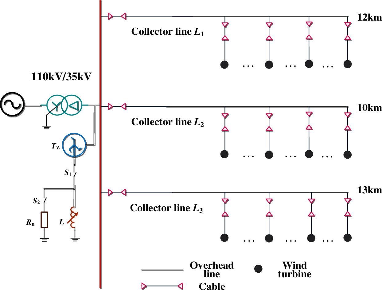
Figure 4: Mountain wind farm simulation model
4.2 Analysis of Simulation Example
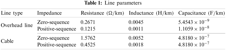
Supposed a permanent SLG fault occurs on collector line L1 in the ungrounded system, ZSV and ZSC are shown in Figs. 5a and 5b.
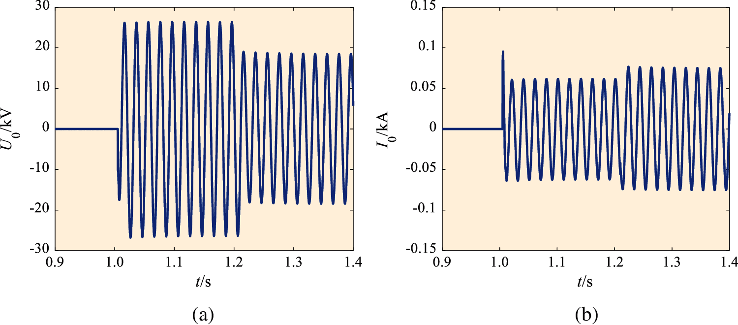
Figure 5: Variation characteristics of the zero-sequence component (a) ZSV (b) ZSC
As ZSV is detected in the ungrounded system, the data of 20 ms after the fault is selected to calculate the zero-sequence power variation. The zero-sequence power variation is 845 kW that is higher than the threshold value of protection
Supposed an instantaneous fault occurs on collector line L1 in the ungrounded system, and ZSV and current are shown in Figs. 6a and 6b.
As ZSV is detected in the ungrounded system, the data of 20 ms after the fault is selected to calculate the zero-sequence power variation. The zero-sequence power variation is 783 kW that is higher than the threshold value of protection
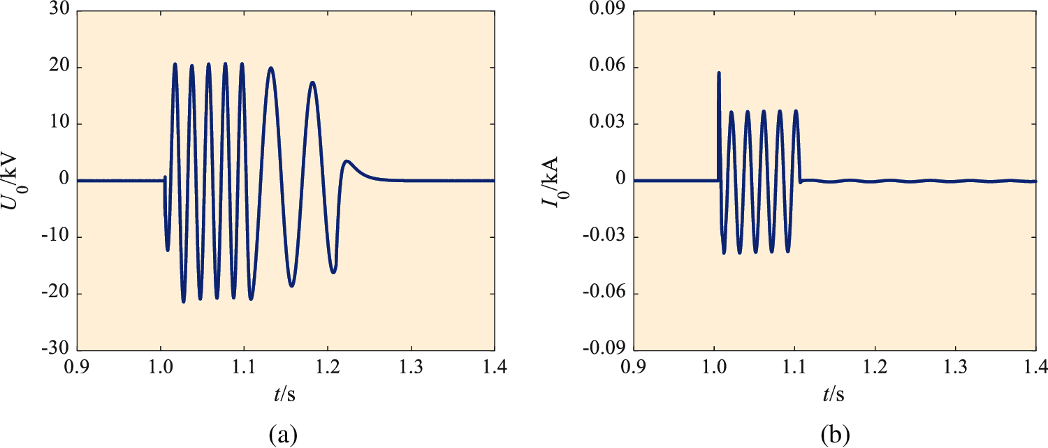
Figure 6: Variation characteristics of the zero-sequence component (a) ZSV (b) ZSC
4.2.3 Identification of Fault Property
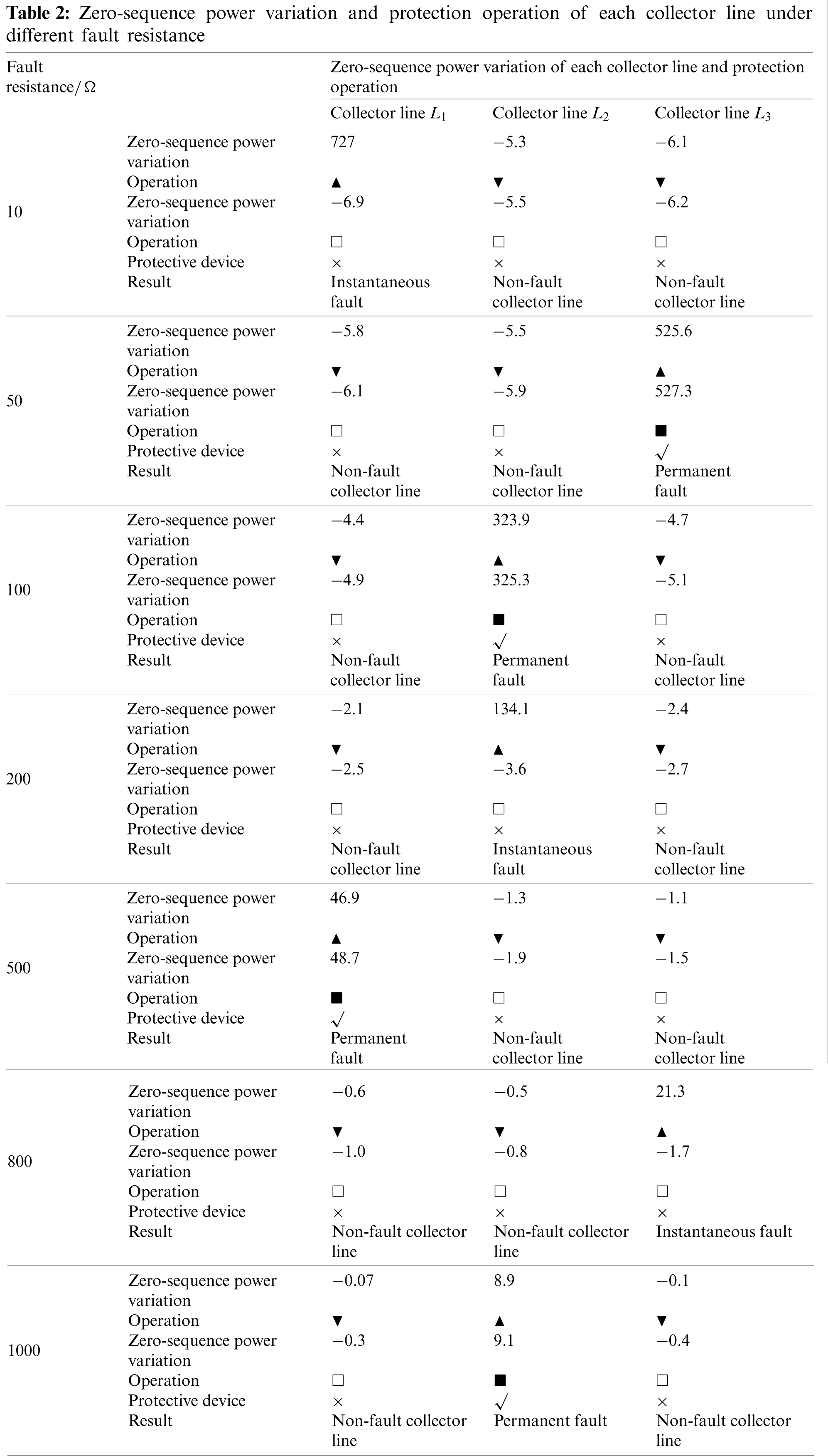
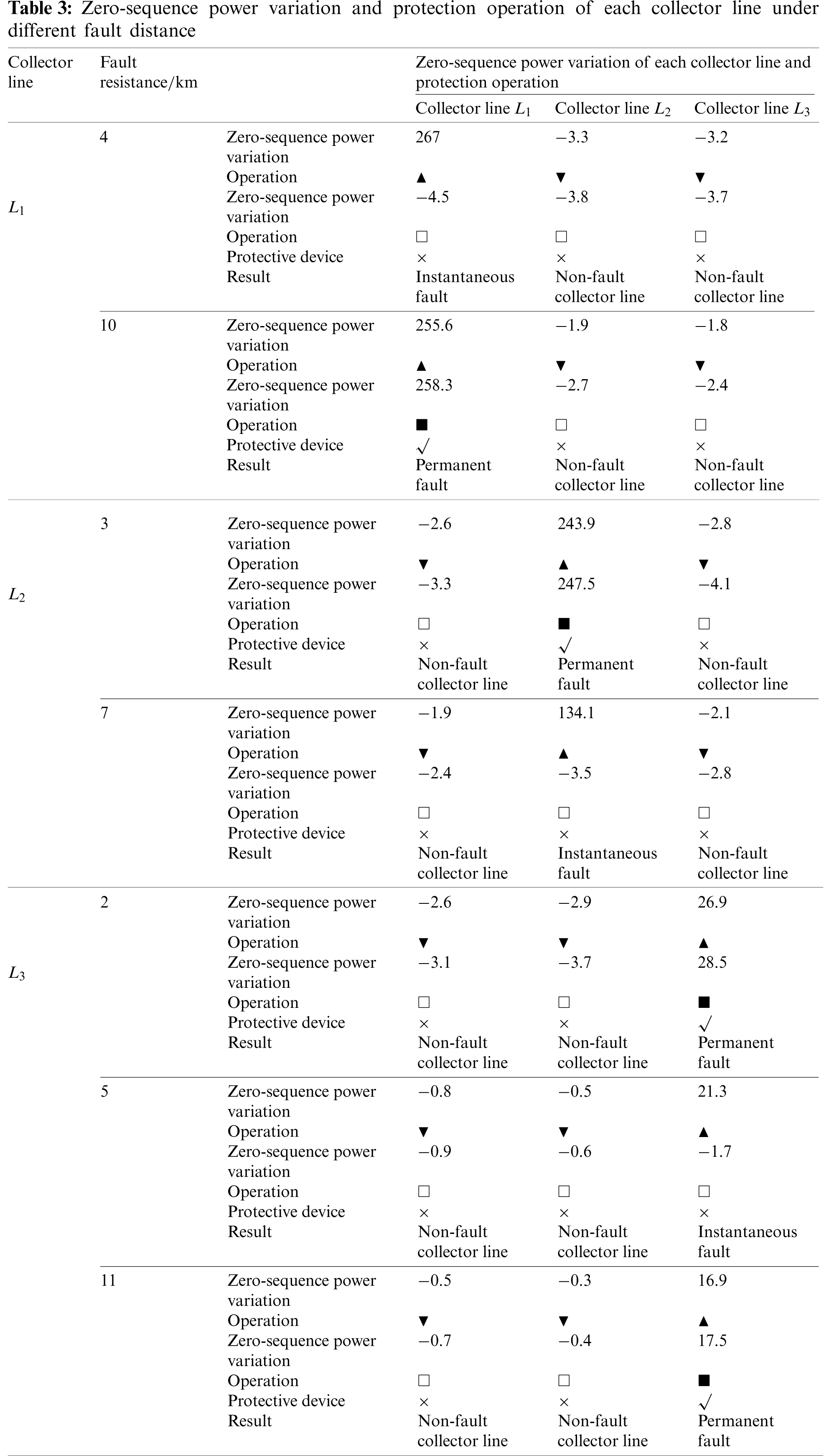
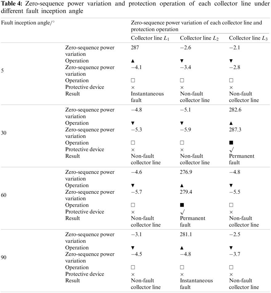
To test the validity of the based on zero-sequence power variation protection, SLG under different fault resistance, fault distance and fault inception angle are set in different collector lines of the mountain wind farm simulation model, which the zero-sequence power variation of each collector line can be obtained and is listed in Tables 2–4.
With the increase of fault resistance, zero-sequence power variation of non-fault collector line and fault collector line gradually decrease, however, zero-sequence power variation of fault collector line is still higher than that of non-fault collector line. It can be seen that the zero-sequence power variation of the fault collector line is greater than the protection setting value
In Tables 2–4, ‘▲’ indicates ASC is put into the system; ‘▼’ means ASC is not put into the system; ‘■’ denotes LR is put into the system; ‘□’ represents LR is not put into the system; ‘√’ expresses protective device operation and clears the fault; ‘
Table 3 displays zero-sequence power variation and protection operation of each collector line under different fault distance. As a SLG occurs in different fault distance under different collector line, zero-sequence power variation of fault collector line is greater than the protection setting value
Table 4 shows zero-sequence power variation and protection operation of each collector line under different fault inception angle. Non-fault collector lines are less than the protection setting value
Through the analysis of ZSV and ZSC after SLG occurs in mountain wind farm based on multi-mode grounding, a zero-sequence power variation protection method is proposed that is applicable to the collector line of the mountain wind farm. The effectiveness of zero-sequence power variation protection is verified by simulation, the following conclusions are obtained.
(1) The protection criterion is constructed and based on the fact that the zero-sequence power variation of non-fault collector line is small, while the zero-sequence power variation of fault collector line can reflect the active power component of fault resistance.
(2) The multi-mode grounding in the mountain wind farm is conducive to the disappearance of the instantaneous fault so that the protection will not mal-operation; when high impedance grounding fault occurs, the protection will not refuse to operate; it can improve the reliability of protection.
(3) The proposed protection criterion only needs ZSV and ZSC of each collector lines before and after the fault, which is easy to realize in the multi-mode grounding of the mountain wind farm.
(4) Based on zero-sequence power variation protection is verified by the simulation results, which can efficiently differentiate fault property and reliably protect the fault collector line and that is not affected by operating conditions such as fault resistant, fault distance, and inception time.
Acknowledgement: The authors gratefully acknowledge the National Natural Science Foundation of China (51667010 and 51807085), and the support of the Major Science and Technology Projects in Yunnan Province (202002AF080001).
Funding Statement: This paper is supported in part by the National Natural Science Foundations of China, and the Major Science and Technology Projects in Yunnan Province under Grant Nos. 51667010, 51807085, and 202002AF080001.
Conflicts of Interest: The authors declare that they have no conflicts of interest to report regarding the present study.
1. Gounder, Y. K., Nanjundappan, D., Boominathan, V. (2016). Enhancement of transient stability of distribution system with SCIG and DFIG based wind farms using STATCOM. IET Renewable Power Generation, 10(8), 1171–1180. DOI 10.1049/iet-rpg.2016.0022. [Google Scholar] [CrossRef]
2. Ayoub, H., Bani-Hani, E. H. (2020). Performance and cost analysis of energy production from offshore wind turbines. Energy Engineering, 117(1), 41–47. DOI 10.32604/EE.2020.010412. [Google Scholar] [CrossRef]
3. Yang, B., Wang, J. B., Zhang, X. S., Yu, T., Yao, W. et al. (2020). Comprehensive overview of meta-heuristic algorithm applications on PV cell parameter identification. Energy Conversion and Management, 208(5), 112595. DOI 10.1016/j.enconman.2020.112595. [Google Scholar] [CrossRef]
4. Jiao, Z. Q. (2012). A survey on relay protection for grid-connection of large-scale wind farm. Power System Technology, 3(6), 195–201. DOI 10.13335/j.1000-3673.pst.2012.07.044. [Google Scholar] [CrossRef]
5. Eriksen, P. B., Ackermann, T., Abildgaard, H., Smith, P., Winter, W. et al. (2005). System operation with high wind penetration. IEEE Power Energy Magazine, 36(7), 65–74. DOI 10.1109/MPAE.2005.1524622. [Google Scholar] [CrossRef]
6. Yang, B., Yu, T., Zhang, X. S., Li, H. F., Shu, H. C. et al. (2019). Dynamic leader based collective intelligence for maximum power point tracking of PV systems affected by partial shading condition. Energy Conversion and Management, 179(18), 286–303. DOI 10.1016/j.enconman.2018.10.074. [Google Scholar] [CrossRef]
7. Song, G. B., Wang, C. Q., Wang, T., Mostafa, K., Kang, X. N. et al. (2017). A phase selection method for wind power integration system using phase voltage waveform correlation. IEEE Transactions on Power Delivery, 32(2), 740–748. DOI 10.1109/TPWRD.2016.2577890. [Google Scholar] [CrossRef]
8. Yang, B., Zhong, L. E., Zhang, X. S., Shu, H. C., Yu, T. et al. (2019). Novel bio-inspired memetic slap swarm algorithm and application to MPPT for PV systems considering partial shading condition. Journal of Cleaner Production, 215(3), 1203–1222. DOI 10.1016/j.jclepro.2019.01.150. [Google Scholar] [CrossRef]
9. Zhang, K., Zhu, Y. L., Liu, X. C. (2019). A fault locating method for multi-branch hybrid transmission lines in wind farm based on redundancy parameter estimation. Journal of Modern Power Systems and Clean Energy, 7(5), 1033–1043. DOI 10.1007/s40565-018-0476-3. [Google Scholar] [CrossRef]
10. Zheng, T., Zhao, Y. T., Zhu, Y. F. (2020). Overcurrent protection scheme for collector lines in wind farm based on fault component current correlation analysis and multi-agent system. IET Renewable Power Generation, 14(2), 313–320. DOI 10.1049/iet-rpg.2019.0315. [Google Scholar] [CrossRef]
11. Jin, N., Xing, J. W., Liu, Y., Li, Z. T., Lin, X. N. (2018). A novel single-phase-to-ground fault identification and isolation strategy in wind farm collector line. International Journal of Electrical Power & Energy Systems, 94(4), 15–26. DOI 10.1016/j.ijepes.2017.06.031. [Google Scholar] [CrossRef]
12. Chen, J. H., Li, R. X., Guo, Z. M., Zhang, H., Yang, Z. G. et al. (2015). A robust interval wind power dispatch method considering wind collecting power lines outage. Proceedings of CSEE, 35(12), 2936–2942. DOI 10.13334/j.0258-8013.pcsee.2015.12.003. [Google Scholar] [CrossRef]
13. Shu, H. C. (2008). Fault line selection of distribution power system. Beijing: China Machine Press (in Chinese). [Google Scholar]
14. Matevosyan, J., Ackermann, T., Bolik, S. (2005). Wind power in power systems. UK: John Wiley. [Google Scholar]
15. Ye, X., Qiao, Y., Lu, Z. X. (2012). Cascading tripping out of numerous wind turbines in China: Fault evolution analysis and simulation study, pp. 1–11. San Diego, CA, USA: IEEE Power & Energy Society General Meeting. [Google Scholar]
16. Hooshyar, A., Azzouz, M. A., EI-Saadany, E. F. (2014). Distance protection of lines connected to induction generator-based wind farms during balanced faults. IEEE Transactions on Sustainable Energy, 5(4), 1193–1203. DOI 10.1109/TSTE.2014.2336773. [Google Scholar] [CrossRef]
17. Zhang, B. H., Yin, X. G. (2013). Power system relay protection. Beijing: China Electric Power Press (in Chinese). [Google Scholar]
18. Tong, N., Lin, X. N., Li, Z. T., Zhang, R. (2014). Study for reciprocal effect between overcurrent protection and doubly-fed induction generator feeding current under the condition of symmetrical voltage sag. Proceedings of CSEE, 34(22), 3806–3814. DOI 10.13334/j.0258-8013.pcsee.2014.22.028. [Google Scholar] [CrossRef]
19. Ouyang, J. X., Xiong, X. F., Zhang, H. Y. (2011). Characteristics of DFIG-based wind generation under grid short circuit. Proceedings of CSEE, 31(22), 17–25. DOI 10.1080/17415993.2010.547197. [Google Scholar] [CrossRef]
20. Pannell, G., Atkinson, D. J., Zahawi, B. (2010). Minimum-threshold crowbar for a fault-ride-through grid-code-compliant DFIG wind turbine. IEEE Transactions on Energy Conversion, 25(3), 750–759. DOI 10.1109/TEC.2010.2046492. [Google Scholar] [CrossRef]
21. Okedu, K. E., Muyeen, S. M., Takahashi, R., Tamura, J. (2012). Wind farms fault ride through using DFIG with new protection scheme. IEEE Transactions on Sustainable Energy, 3(2), 242–254. DOI 10.1109/TSTE.2011.2175756. [Google Scholar] [CrossRef]
22. Yang, B., Jiang, L., Yao, W., Wu, Q. H. (2015). Perturbation estimation based coordinated adaptive passive control for multimachine power system. Control Engineering Practice, 44(11), 172–192. DOI 10.1016/j.conengprac.2015.07.012. [Google Scholar] [CrossRef]
23. Zhang, X. S., Yu, T., Yang, B., Li, L. (2016). Virtual generation tribe based robust collaborative consensus algorithm for dynamic generation command dispatch optimization of smart grid. Energy, 101(1), 34–51. DOI 10.1016/j.energy.2016.02.009. [Google Scholar] [CrossRef]
24. Zhang, B. H., Wang, J., Yuan, B., Hao, Z. G., Huang, R. M. et al. (2013). Impact of wind farm integration on relay protection (4Performance analysis for wind farm outgoing transmission line protection. Electric Power Automation Equipment, 33(4), 1–5. DOI 10.3969/j.issn.1006-6047.2013.04.001. [Google Scholar] [CrossRef]
25. Mahfouz, A. M. M. A., El-Sayed, M. A. H. (2016). Enhanced fault location algorithm for smart grid containing wind farm using wireless communication facilities. IET Generation, Transmission & Distribution, 10(9), 2231–2239. DOI 10.1049/iet-gtd.2015.1488. [Google Scholar] [CrossRef]
26. Yu, K., Lin, X. N., Tong, N., Li, H., Zhao, H. et al. (2018). A hyperbolic tangent function operation characteristic based inverse-time protection method of wind farm collector line. Proceedings of CSEE, 38(13), 3846–3857. DOI 10.13334/j.0258-8013.pcsee.171694. [Google Scholar] [CrossRef]
27. Ma, J., Zhang, W. B., Liu, J., Thorp, J. S. (2018). A novel adaptive distance protection scheme for DFIG wind farm collector lines. International Journal of Electrical Power & Energy Systems, 94(7), 234–244. DOI 10.1016/j.ijepes.2017.07.008. [Google Scholar] [CrossRef]
28. Che, Q., Lu, Y. P. (2013). Research on wind farm relay protection value setting based on crowbar circuit LVRT technology. Power System Protection & Control, 41(2), 97–102 (in Chinese). DOI 10.7667/j.issn.1674-3415.2013.02.016. [Google Scholar] [CrossRef]
29. Wu, H., Sun, J. L., Qiao, L. W., Qiao, Y., Lu, Z. X. et al. (2016). Short circuit current characteristics and calculation of current protection setting of feeder lines in wind farms considering LVRT. Power System Technology, 40(10), 3019–3028. DOI 10.13335/j.1000-3673.pst.2016.10.014. [Google Scholar] [CrossRef]
30. Prasad, C. D., Biswal, M., Abdelaziz, A. Y. (2020). Adaptive differential protection scheme for wind farm integrated power Network. Electric Power Systems Research, 187, 1–11. DOI 10.1016/j.epsr.2020.106452. [Google Scholar] [CrossRef]
31. Dong, J., Li, Y. F., Shu, H. C., Yu, J. L., He, J. (2020). Joint active-passive detection method for fault section of radial feeder. Automation of Electric Power Systems, 44(11), 135–145. DOI 10.7500/AEPS20190613002. [Google Scholar] [CrossRef]
32. Tang, T., Huang, C., Hua, L., Zhu, J. R., Zhang, Z. D. (2018). Single-phase high-impedance fault protection for low-resistance grounded distribution network. IET Generation, Transmission & Distribution, 12(10), 2462–2470. DOI 10.1049/iet-gtd.2017.1547. [Google Scholar] [CrossRef]
 | This work is licensed under a Creative Commons Attribution 4.0 International License, which permits unrestricted use, distribution, and reproduction in any medium, provided the original work is properly cited. |