| Energy Engineering |
DOI: 10.32604/EE.2021.017433
ARTICLE
The Effect of Injected Air Bubble Size on the Thermal Performance of a Vertical Shell and Helical Coiled Tube Heat Exchanger
1Engineering Technical College, Al-Furat Al-Awsat Technical University, Al-Najaf, 31001, Iraq
2Department of Chemical and Process Engineering, Faculty of Engineering and Physical Sciences, University of Surrey, Guildford, GU2 7XH, UK
*Corresponding Author: Hameed B. Mahood. Email: hbmahood@yahoo.com
Received: 10 May 2021; Accepted: 25 June 2021
Abstract: In the present study, the effect of injecting air bubble size on the thermal performance of a vertical counter-current shell and coiled tube heat exchanger is experimentally investigated. The experiments were accomplished in a cylindrical shape heat exchanger with a 50 cm height and 15 cm outer diameter. Copper coil with 3.939 m equivalent length and 0.6 cm outer diameter was used to carry the hot fluid (water). Four different cold fluid (shell side) flow rates
Keywords: Sparger; smooth helical coil; vertical shell; heat exchanger; injection bubbles
Nomenclature
| As | Heat transfer area (m2) |
| cp | Specific heat (J/kg. k) |
| di | Inner coiled tube diameter, mm |
| Dc | Curvature diameter (mm) |
| H | Height column (mm) |
| K | Thermal conductivity (W/m °C) |
| L | Tube length (mm) |
| LMTD | Logarithmic mean temperature difference (°C) |
| | Mass flow rate (kg/s) |
| N | Number of turns |
| NTU | Number thermal unit |
| p | Coil pitch (mm) |
| q | Heat transfer rate (W) |
| Qs | Shell side (cold water) Flow rate (LPM) |
| Qh | Coil side (hot water) Flow rate (LPM) |
| Qa | Air Flow rate (LPM) |
| t | Thickness (mm) |
| ΔT | Temperature difference (°C) |
| U | Overall heat transfer coefficient (W/m2. °K) |
| W | Total uncertainty in the measurement |
| Sub-script | |
| c | Cold fluid |
| h | Hot fluid |
| i | Inner |
| max | Maximum |
| min | Minimum |
| o | Outer |
| Greece symbols | |
| ε | Effectiveness |
| ρ | Fluid density (kg/m2) |
| μ | Dynamic viscosity (kg/m. s) |
| ѵ | Kinematic viscosity (m2/s) |
Energy demand is ever rising worldwide because of the intense industrialization and population growth [1]. Fossil fuel, such as oil and gas, seems the significant energy source that meets the increasing demand. In addition to the challenge of the ability of fossil fuel to play this role, the fluctuation of fossil fuel price and its tendency to produce pollutant gases entails finding alternative solutions. In this context, enhancing energy conversion and extraction equipment, such as heat exchangers, could mitigate the unwanted unquenches that inevitably increase fossil fuel burning. Accordingly, various techniques, which passive and active techniques can mainly characterize, enhance heat exchanger’s efficiency and reduce heat losses [2].
The heat exchanger can be defined as a device used to transfer thermal energy from a hot stream to another cold stream. As an indirect-contact heat exchanger, Shell and tube heat exchangers are widely used in various applications. These can include many industries such as the petrochemical industry, power generation plants, and cooling and heating systems [3]. Therefore, the efficiency improvement of this heat exchanger type has gained huge attention during the last decades. However, all enhancement methods concentrate on raising the fluid flow’s turbulence level and mixing the heat exchanger’s thermal boundary layer [4]. Consistent, corrugated tubes, turbulators, and fined tubes are examples of the passive enhancement technique that is exploited. On the other hand, active enhancement methods, such as vibration and electromagnetic fields containing external forces, have also been applied.
More recently, air bubble injection has been suggested as one of the promising enhancement methods of heat exchanger thermal performance [5,6]. Upon air injected into a liquid, air bubbles will form within the liquid. However, these bubbles’ number, shape, size, and distribution rely on the injection technique and the fluid’s properties. Once the bubbles form in the liquid, naturally, they float and move upward due to the buoyancy force, which initiates by the difference in the densities of the liquid and air. This random motion of bubbles will mix the liquid bulk and break down the hydrodynamic and thermal boundary layers, enhancing heat exchange in thermal systems, such as heat exchangers. However, the mixing level depends on many factors, such as the air bubbles flow rate, number of bubbles, size of bubbles, and heat exchanger design.
Dizaji et al. [7] injected air bubbles into a shell and coiled-tube heat exchanger to increase thermal performance. A spiral tube was suggested as a system to inject bubbles. Their findings elucidated that air bubble injection and bubbles mobility (because of buoyancy force) can intensify the NTU and energy loss by mixing the thermal boundary layer and increasing the turbulence level of the fluid in the shell. Furthermore, the study demonstrated that the value of NTU and effectiveness could significantly be improved due to air bubbles injection. Khorasani et al. [8] investigated the use of an injection mechanism to infuse air bubbles into the horizontal shell and the helical coil heat exchanger in parallel flow and counter flow situations. A wide range of airflow rates (1–5 LPM) and various shell-side water flow rates (1–5 LPM) have shown that the NTU rises by 1.3 to 4.3 times due to the injecting air bubbles. It was observed that the highest increase occurred in the counterflow case. It was also conducted that the exergy loss increased from 1.8 to 14.2 times the value without air injection. The maximum effectiveness value was 0.815 could be reached in the counterflow situation. Nouri et al. [9] used an experimental setup to investigate the influence of air bubble injection on skin friction at a rotating center. The obtained results indicated that void fractions less than 4% caused a 90% decrease in skin friction. Kitagawa et al. [10–14] experimentally analyzed the heat transfer enhancement over a flat plate by hydrogen bubble injection for various flow regimes natural convection (laminar, transition to turbulent, and turbulent), as well as laminar mixed convection. It was conducted that the heat transfer coefficients of laminar natural convection increased by 1.35–1.85 times and laminar mixed convection increased by 1.24–1.38 times, and transition zone natural convection increased by approximately 1.9 turbulent natural convection increased by 1.2–1.3 times. Heat transfer performance and exergy analysis were studied experimentally by Nandan et al. [15] with various air injection sites. Four separate cases with and without air injection in the shell or tube side were considered, and the effects were compared. The study results illustrated that inserting air bubbles in the tube increases the heat transfer rate by 25–40% at various Reynolds Number ranges. The effect of air injection at various points also impacts overall heat transfer and dimensionless exergy loss. El-Said et al. [16] tested the possibility of enhancing the thermal performance of many tube heat exchangers by pumping the air as tiny bubbles using cross-flow and parallel flow air injection techniques. In their study, the air and shell side water flow rates were changed between 1 and 5 LPM and 12–21 LPM, respectively, with a constant tube side water flow rate. The study’s findings showed that the air bubble injection significantly improved the heat exchanger’s efficiency and that the cross-flow injection technique had a more significant benefit. The augmentation on the U caused by cross-air injection into the heat exchanger shell was 131%–176%, depending on air and shell side water flow rates. Baqer et al. [17] examined the optimal operating conditions for injecting a sub-millimeter air bubble into the spiral tube heat exchanger’s side housing. The implemented shell-side flow rates (cold water), airflow rates, and coil-side flow rates (hot water) were varied from 2 LPM to 10 LPM, from 0 to 10 LPM, and 1 LPM to 2 LPM, respectively, with three temperature variations (i.e., 20°C, 30°C, and 36°C). The findings of the study revealed that the most effective shell-side flow rate was 6 LPM, and the airflow rate was more than 6 LPM. The maximum augmentation in the NTU and the effectiveness were 1.93 and 0.83, respectively, while the NTU’s minimum value and effectiveness were 0.66 and 0.63, respectively. Kreem et al. [18] observed an intimate thermal mixing of bubbles in the heat exchanger shell and proposed that this could be the main reason for improving the heat exchanger’s thermal performance. More recently, this was corroborated by Hasan et al. [19] when they observed that the helically coiled tube heat exchanger’s axial temperature distribution was the same for a shorter period after air bubbles were introduced into the heat exchanger shell. Shukla et al. [20] investigated the impact of air bubble diameter on the effectiveness, NTU numerically, and overall heat transfer coefficient of shell and helical coil heat exchangers using ANYSYS FLUENT 14.5 CFD software. Four different air bubble diameters (0.05, 0.1, 0.3, 0.5 and 0.4 mm) were tested. The CFD results revealed that air bubbles with a diameter of 0.7 mm have the greatest heat transfer. Furthermore, the greatest increases in NTU, overall heat transfer coefficient, and effectiveness were 1.39, 1327, and 0.74, respectively. Subesh et al. [21] investigated two different air bubble injection techniques (parallel and cross-flow) on the shell side and heat exchanger tube by the applied wide range of injected airflow and cold water (1 to 6 LPM of airflow rates and 10 to 20 LPM shell side water flow rates were transformed with constant tube side hot water flow rate). It was observed (Subesh et al.) that the result of cross-injection on ε, NTU, and U of the heat exchanger was more than that of the second parallel injection for all experimental conditions. Furthermore, the pressure loss in the cross-injection method was higher than in the shell-side parallel injection method. Ghashim et al. [22] examined experimentally the influence of injecting tiny air bubbles on the heat transfer and pressure drop (Δp) of a helically coiled tube heat exchanger running in turbulent flow conditions. The airflow rate was (1.5, 2.5, and 3.5 l/min), the hot fluid’s Reynold number (Re) was between 9000 and 50000, and the effectiveness, NTU, and exergy losses were assessed. The results showed that the air injected led to a 64%–126% rise in Nu, raising the pressure drop from 66%–85% for the entire range Reynold number (Re) tested. Sokhal et al. [23] examined the influence of injection bubbles on the heat exchanger shell and tube’s output and efficiency. The results showed that the air bubble flow rates rise increased the heat exchanger’s performance as the energy loss increases with an increase in the flow rate. Contrary to no bubble injection, the minimum dimensionless loss of exercise was between 27.49% and 13%.
As clearly demonstrated by the literature review, although a relatively large number of studies have been carried out regarding implementing the air injection technique to enhance the thermal performance of heat exchangers, there was no attention focused on the effect of the injected air bubble size. However, the current study seeks to fill this gap by examining the influence of bubble size on enhancing the thermal performance of a vertical shell and coil tube heat exchanger. To do so, different operational conditions, such as the shell side flow rate, coil side flow rate, and injected air bubble flow rate and bubble size, were experimentally tested.
2 Explanation of Tests and Methods
2.1 Experimental Setup Configuration and Definition
Figs. 1 and 2 demonstrate the photographic view and schematic diagram of the experimental setup. The system consists of four separate parts; the test section, the hot water path section, the cold-water path section, and the air injection path section. The test section consists of heat exchangers for shells and a helically smooth coil tube. The detailed explanations of the configuration sections are as follows.
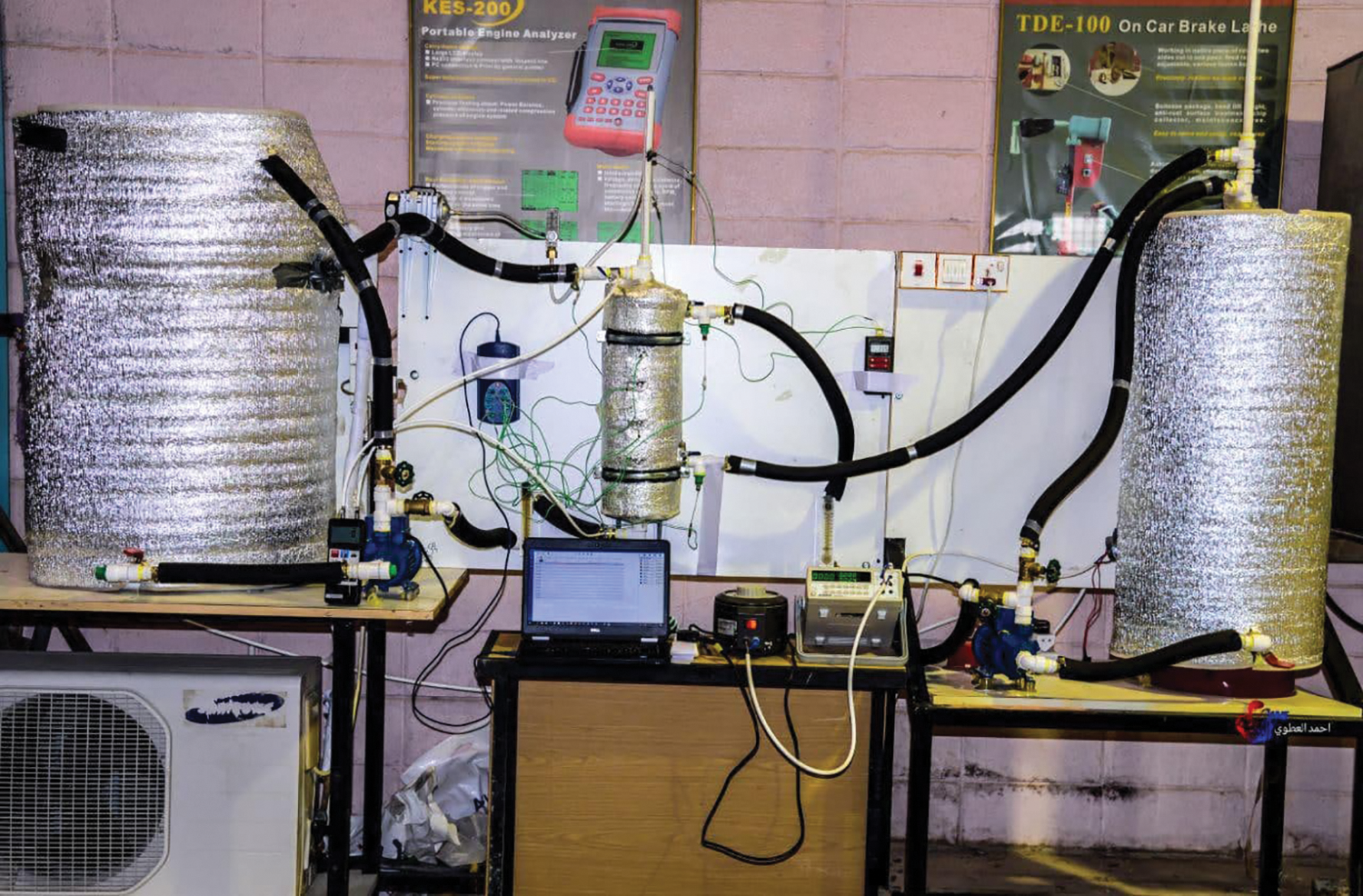
Figure 1: A photographic image of the setup of experiments
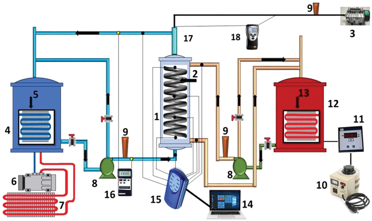
Figure 2: A schematic illustration of the test setup: 1. housing tube, 2. helically smooth coiled tube, 3. air pump, 4. a cold storage tank, 5. evaporator, 6. compressor, 7. condensor, 8. water pump, 9. rotameter, 10. variac, 11. wattmeter, 12. a hot storage tank, 13. heater. 14. personal computer (pc), 15. recorder of data, 16. manometer, 17. a slit of air, 18. air temperature thermometer
2.1.1 Shell and Helical Smooth Coil Tube Heat Exchanger
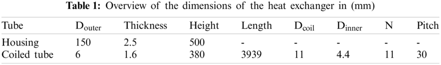
Traditional single-pass housing and helical smooth coil tube heat exchanger were used in the experiments. Hot water flows through the coil tube side made of copper, whereas cold water flows through the shell side of PVC in a counter-current configuration. It has an internal diameter of 14.5 cm, a thickness of 0.25 cm, and a height of 50 cm. Besides, 11 coil rings with an external diameter of 11 cm are mounted within the housing. The gap between the rings (pitch) is 3 cm, and the coil’s overall height is 38 cm. Further details are given in Tab. 1. The shell’s exterior surface is insulated with an 8 mm thick polyolefin foam insulation layer (EPE) with extremely low heat conductivity (0, 002 W/m. K) [17]. This is also utilized as a thermal insulator surrounding the hot water tank, cold water tank, and test section to reduce ambient heat losses.
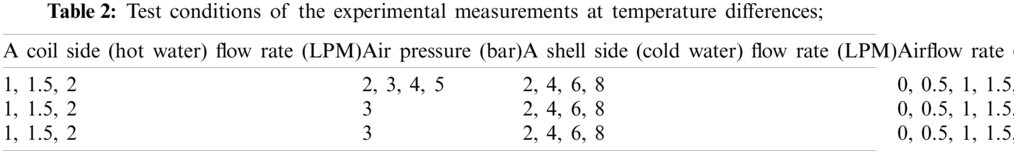
The general view of the test section and air sparger is illustrated in Figs. 3 and 4. Fig. 4 shows that there is one location for air infusion; parallel infusion from the shell’s bottom side. Three spiral-shaped plastic tubings (sparger) samples with different hole diameters (0.1, 0.8, and 1.5 mm) were used through the experiments. On the other hand, the number of holes in each case was constant at 1400 holes. The outer diameter of the sparger is 14.5 cm, the outer diameter of the plastic tube is 1 cm, and the inner diameter of the plastic tube is 0.8 cm. ACO-318 Electromagnetic air compressor made in China was used to supply fresh air to the sparger unit.
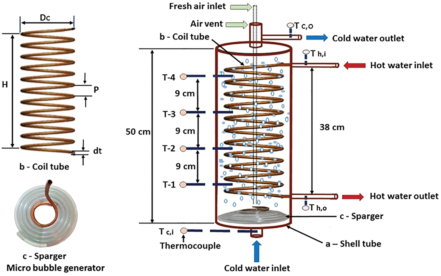
Figure 3: Test section
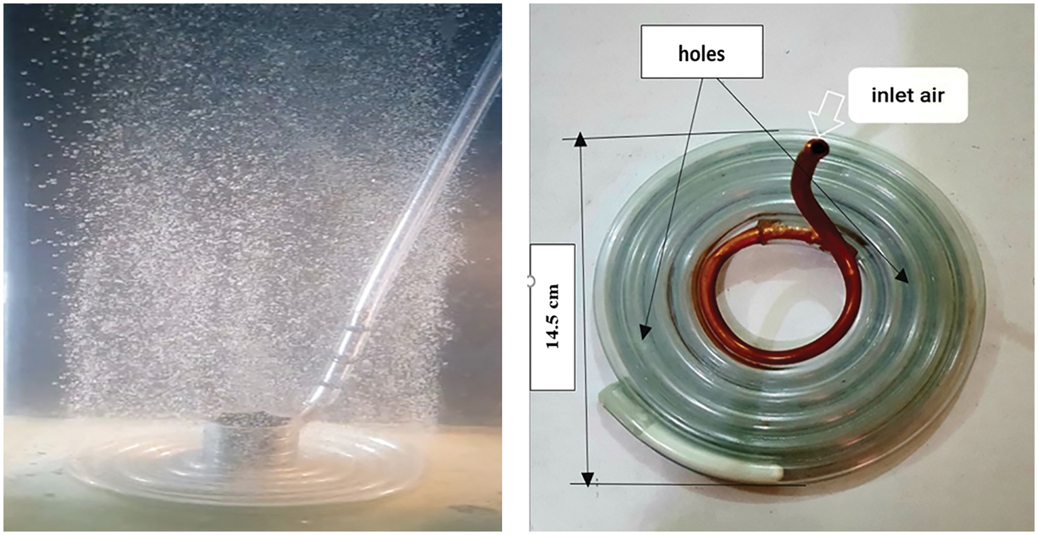
Figure 4: Sparger
There are two water loops; a hot water loop and a cold-water loop (Fig. 2). The hot water loop consists of a water storage tank (120 L) with an electrical water heater with a capacity of 3 kW, a variac and a wattmeter (see Figs. 1 and 2) and a centrifugal pump with a capacity of 30 LPM for hot water pumping from/to heaters and the heat exchanger tube side. Variac was used as a sine voltage controller. The variac and wattmeter were used together to maintain the coiled tube’s inlet water at a constant temperature, allowing all experiments to be carried out at the same temperature and eliminating or minimizing the uncertainty between them.
The cold-water loop consists of the water storage tank (250 L), rotary compressor, expansion valve, evaporator, refrigerant R-22, and condenser. In addition to a thermostat is used to hold the shell side of the inlet water at a specific temperature and a centrifugal pump with a 30 LPM for cold water pumping from/to the cooler and the heat exchanger side. Meanwhile, each pump has a bypass line to regulate the flow of water quickly.
The experimental measurements include the temperature distribution along with the heat exchanger as well as the pressure drop associated with and without air bubble injection. These measurements were under a different shell and coil sides flow rates and constant initial temperature between the hot water (coil) and cold water (shell) sides. Eight calibrated K-type (Nickel Chromium) thermocouples with extension wire (RS Component Ltd., Nothants, UK) with an accuracy of ±1.1°C or 0.4% were used to measure the inlet and outlet temperatures of hot water and cold water, and the temperature distribution along the shell tube. All these thermocouples are connected to a data logger that shows their measurements directly on a PC. A digital thermometer measured the inlet and outlet air temperature with an accuracy of ±0.2%. The system pressure was determined using an analog pressure gauge type M6304A-Ferro with an accuracy of ±2%. Volumetric flow rates for both hot and cold water are determined by rotameters (panel type) with maximum flow rates of 18 LPM and 4 LPM. Another rotameter (Key Instruments Model FR2000 ±5% Full Scale) was used to quantify air flow rate. A digital manometer (PCE-917) was also used to measure the pressure drop (Δp). The manometer’s measurement range was approximately ±7000 mbar with a resolution of 5 mbar and an accuracy of ±2% (full range).
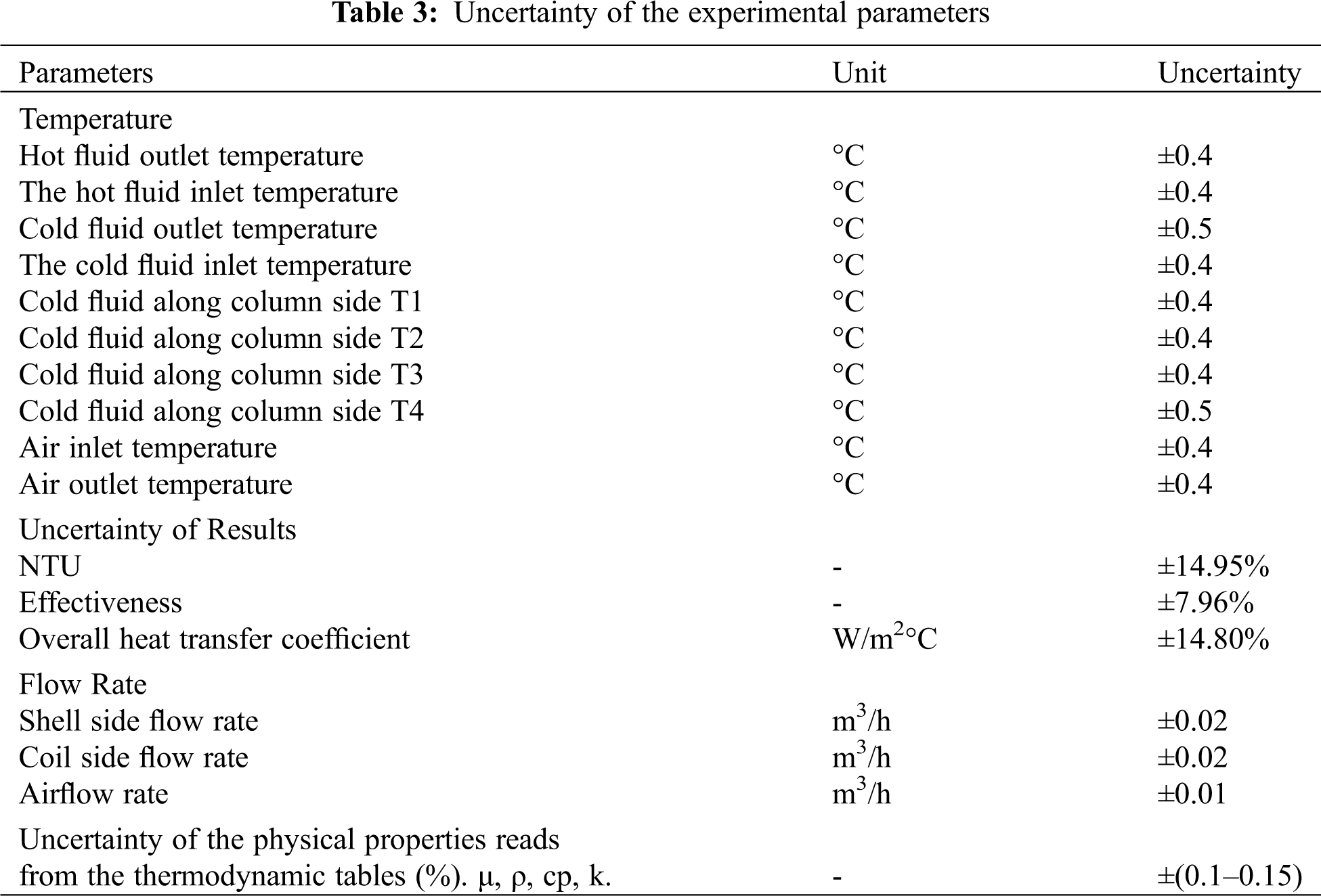
In the present study, 360 runs were conducted. These runs were performed under a constant initial temperature difference between the hot and cold water (20°C). On the other hand, the shell side, coil side, and injected airflow rates were taken variable to investigate their effect on the thermal performance of the heat exchanger. Tab. 2 summarizes the experimental parameters. The influence of the air temperature on the heat transfer was assumed to be negligible due to the low variation in its value measured at the air inlet and outlet, which was about 0.3°C. Under steady-state conditions, the inlet and outlet temperatures and the temperature distribution along the heat exchanger were measured in all experiments.
The calculation of uncertainty due to systematic error and random error was evaluated using the proposed approach of [24], and the estimated uncertainties are summarized in Tab. 3. The following equation was used to quantify the variance of the experimental results:
Moreover, the result is given as:
where:
WR: Uncertainty in the result
and
W1, W2, ……, Wn: Uncertainty in the corresponding variables.
4.1 Effectiveness Analysis (ε)
The effectiveness of the heat exchanger describes the ratio of real to maximum possible heat transfer rates. The effectiveness of the heat exchanger can be assessed as in Eq. (3) below [24]:
4.2 Overall Heat Transfer Coefficient Analysis (u)
The overall heat transfer coefficient (U) is a useful measure to show how the thermal process is optimal under various operating conditions. However, it can be calculated as in Eq. (4) [24]:
where q, As , and ΔTLMTD , represent the heat transfer rate, surface area for heat transfer, and the log-mean temperature difference.
However, the heat transfer rate (q) shown in Eq. (4) is determined on the basis that the water in the shell consumes all heat transfer that comes from the coil side (hot fluid). This assumption was previously used by many researchers [4,20,25], among others. This eliminates some degree of confusion over any amount of heat that is inevitably lost to the atmosphere. The heat transfer rate (q) can therefore be determined from the energy balance as in Eq. (5) [25]:
where (
The log-mean temperature difference can be calculated from Eq. (6) below:
4.3 Number of Heat Transfer Units (NTU) Analysis
The number of heat transfer units (NTU), a dimensionless quantity, can be inferred from Eq. (7) [24]:
where Cmin represents the minimum value of heat transfer capacity
It is observed that the maximum airflow rate (2 LPM) has a minor role compared to the minimum water flow rate (2 LPM). Besides this, the thermal capacity of air (0.02551 W/m. K) is much lower than that of water (0.606 W/m. K). Therefore, the amount of (
In the present study, the air injection technique for improving the thermal performance of vertical shells and coiled tube heat exchangers is used. The assessment of the possible enhancement of the NTU, U, and effectiveness at different operating conditions (Qs = 2, 4, 6 and 8 LPM, Qh = 1 LPM and ΔT = 20°C) at constant bubbles number (1400) as well as to the pressure loss were investigated and quantitatively demonstrated. The merit of this study is that it concerns the effect of the bubble size on the heat exchanger’s thermal enhancement, which did not find in the literature.
Fig. 5 shows the variation of U, NTU, effectiveness, and ΔP with the shell side (cold water) flow rates under different injected airflow rates at constant coil side (hot water) flow rate, bubble number (1400), and bubble diameter 1.5 mm. Evidently, air injection as a small bubble in the heat exchanger’s shell side substantially augmented the heat exchanger’s thermal performance. That tiny bubbles can justify this are eventually moved upward once they formed and are detached at the sparger. This movement, however, led to enhance the thermal and hydrodynamic mixing of the water in the shell. Simultaneously, it would increase the shell side Reynolds number due to the water displacement by the moving bubbles. Accordingly, the heat exchange is improved. On the other hand, this is associated with an increase in pressure loss.
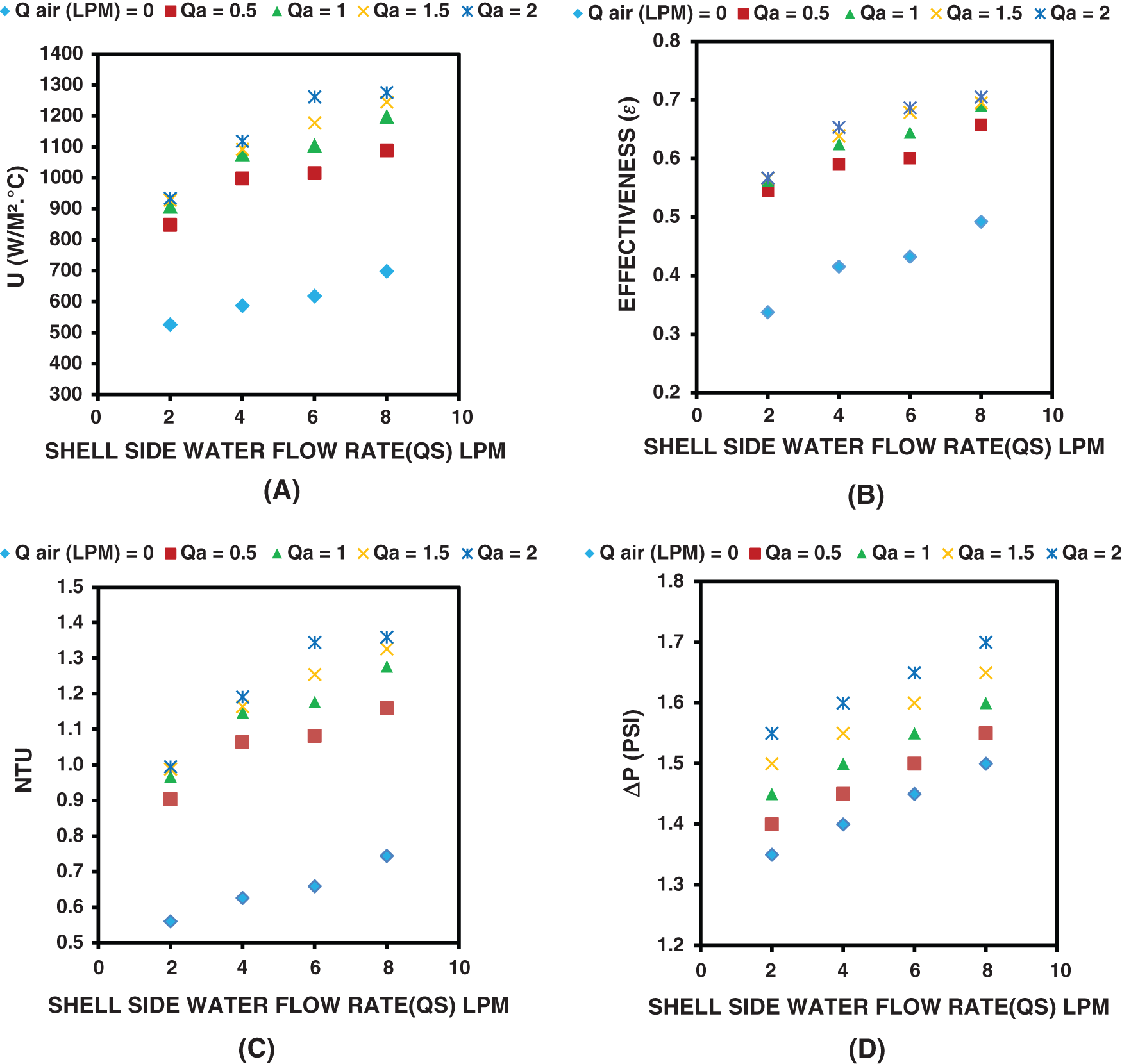
Figure 5: Variation of U, effectiveness, NTU, and pressure drop (ΔP) (sub-figures A, B, C and D, respectively) with Qs for different Qa, Qh = 1 LPM, hole diameter = 1.5 mm, and ΔT = 20°C
However, the maximum improvement in U, NTU, and effectiveness was 153%, 153%, and 68%, respectively. At the same time, the increase in the pressure loss was 1.55, 1.60, 1.65, and 1.7 psi, respectively, at Qa = 2 LPM, Qh = 1 LPM and different Qs.
As mentioned above, the main aim of the present study is to investigate, for the first time, the effect of air bubble size on the thermal performance of the coiled tube heat exchanger. To do so, three different bubble diameters were tested (0.1 mm, 0.8 mm, and 1.5 mm) at the same operational conditions. Fig. 6 demonstrates the variation of U with the shell side (cold water) flow rates for the three different bubble sizes and constant coil side and airflow rate (for each sub-figure A, B, C, and D). Obviously, the bubble size has improved the heat exchanger thermal performance, especially at a low airflow rate (Qa = 0.5 LPM). The larger the bubble size, the higher the thermal efficiency was. This is agreed with the CFD results of [20]. However, one can justify that the current behavior is due to the increase of the shell side Reynolds number, which has an essential and more influential role in the overall heat transfer process by the injected air bubbles. As expected, the larger bubble can push or display more liquid than the small ones, which results in a larger increase in the shell side Reynolds number (Re), leading to more heat transfer enhancement. However, the contribution of thermal mixing due to the bubble motion on the overall thermal enhancement seems to have only a minor effect in comparison with the increase in the shell side Reynolds number, as the size of the water bulk in the shell is much larger than the heat source (coil). At the same time, the duration of the experiment was not adequate to reach a thermal uniformity. Further, the figure also shows clearly that the effect of bubble diameter on U was obvious at the low injected air flow rate (Qa < 1.5 LPM). At this flow regime, the larger bubble diameter results in a larger improvement in U. On the other hand, the role of bubble diameter becomes insignificant (small bubble diameter of 0.1 and 0.8) with increasing the injected air mass flow rate, as there was no improvement in U can be observed. Nevertheless, only the large bubble diameter (bubble diameter equal to or greater than 0.8 mm) still impacts the thermal performance of the heat exchanger, leading to more enhancement.
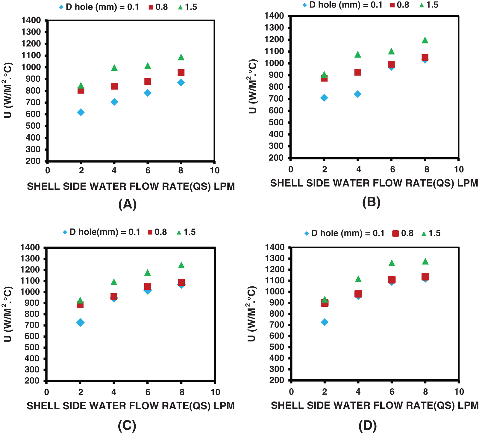
Figure 6: Effect of bubble diameter on the overall heat transfer coefficient for A) Qa = 0.5 LPM, B) Qa = 1 LPM, C) Qa = 1.5 LPM, D) Qa = 2 LPM and ΔT = 20°C
Fig. 7 illustrates the variation of effectiveness and (NTU) with the shell side (cold water) flow rates of the three various bubble diameters and the same operational conditions of Fig. 6 above. Similar to the variation of U (see Fig. 6) is apparently appeared in Fig. 7. The improvement of effectiveness is evident with increasing the shell side flow rate and with increasing bubble diameter. This is consistent with our justification above.
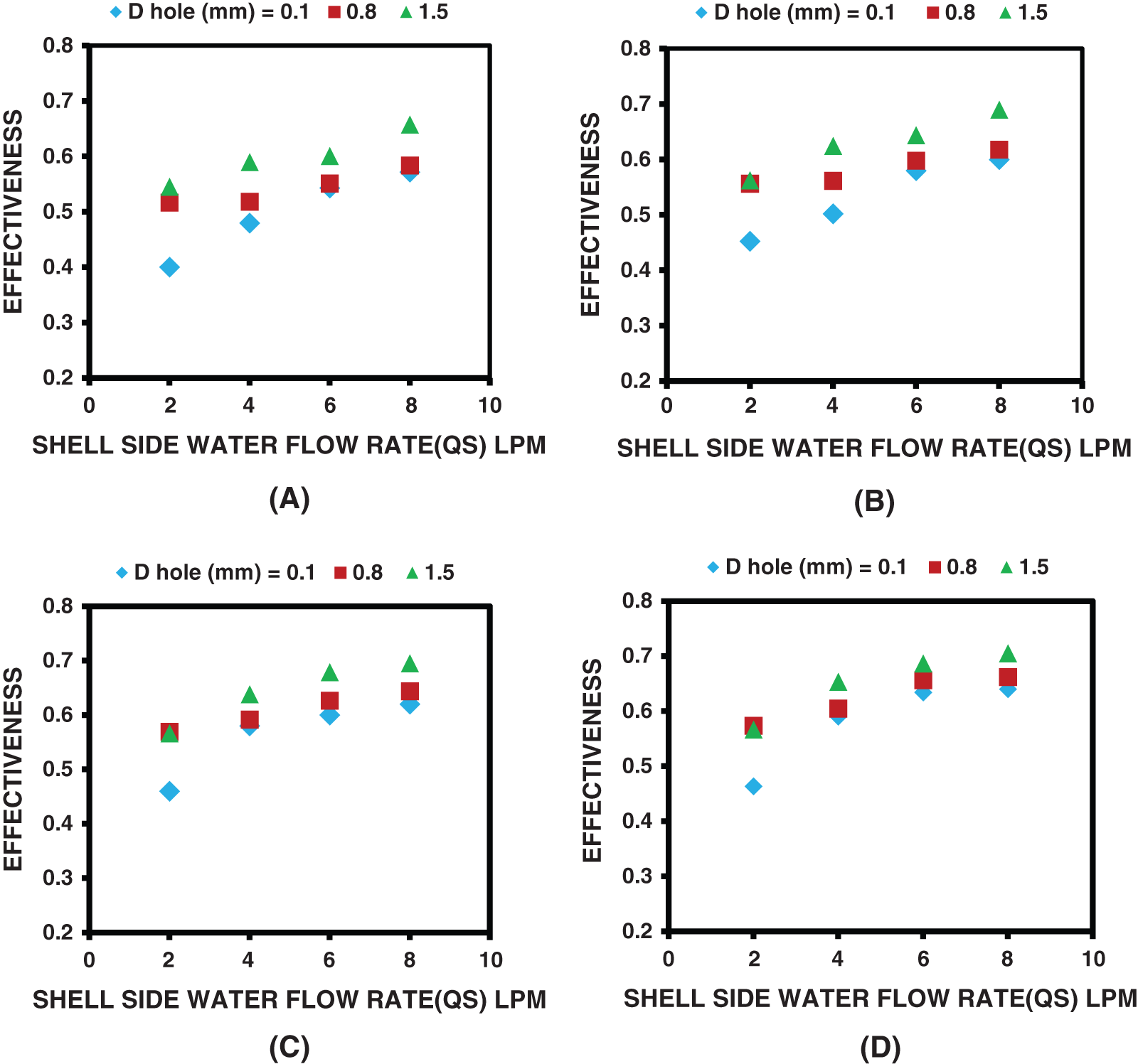
Figure 7: Effect of bubble diameter on effectiveness A) Qa = 0.5 LPM, B) Qa = 1 LPM, C) Qa = 1.5 LPM, D) Qa = 2 LPM and ΔT = 20°C
Similar to Fig. 6 above, the increase in the injected air mass flow rate led to no improvement in the effectiveness of the heat exchanger at a small bubble size (0.1 and 0.8 mm). Beyond those values of bubble diameter, the enhancement in the effectiveness seems obvious. This could lead to conclude that there was an optimum value of the bubble diameter or size at which the enhancement of the thermal performance of the coiled tube heat exchanger can be achieved. Otherwise, one has to carefully maintain the flow of air bubbles for specific bubble sizes to achieve the maximum thermal performance of a heat exchanger.
According to Eq. (7) above, it is expected that the behavior of NTU with the shell mass flow rate under different injected air bubble flow rates will be exactly similar to what has been shown in Fig. 6 above.
Finally, the effect of bubble diameter on the pressure loss is given in Fig. 8 for the same operational condition used in the figures above. Obviously, the increased bubble diameter led to a development in pressure drop along the heat exchanger’s shell side. As previously mentioned, this could be mainly due to the increase in the shell side Re associated with increasing the diameter of bubbles. Surprisingly, the bubble with a diameter of 1.5 and 0.8 mm has nearly the same effect on the pressure drop, contrary to the thermal improvement.
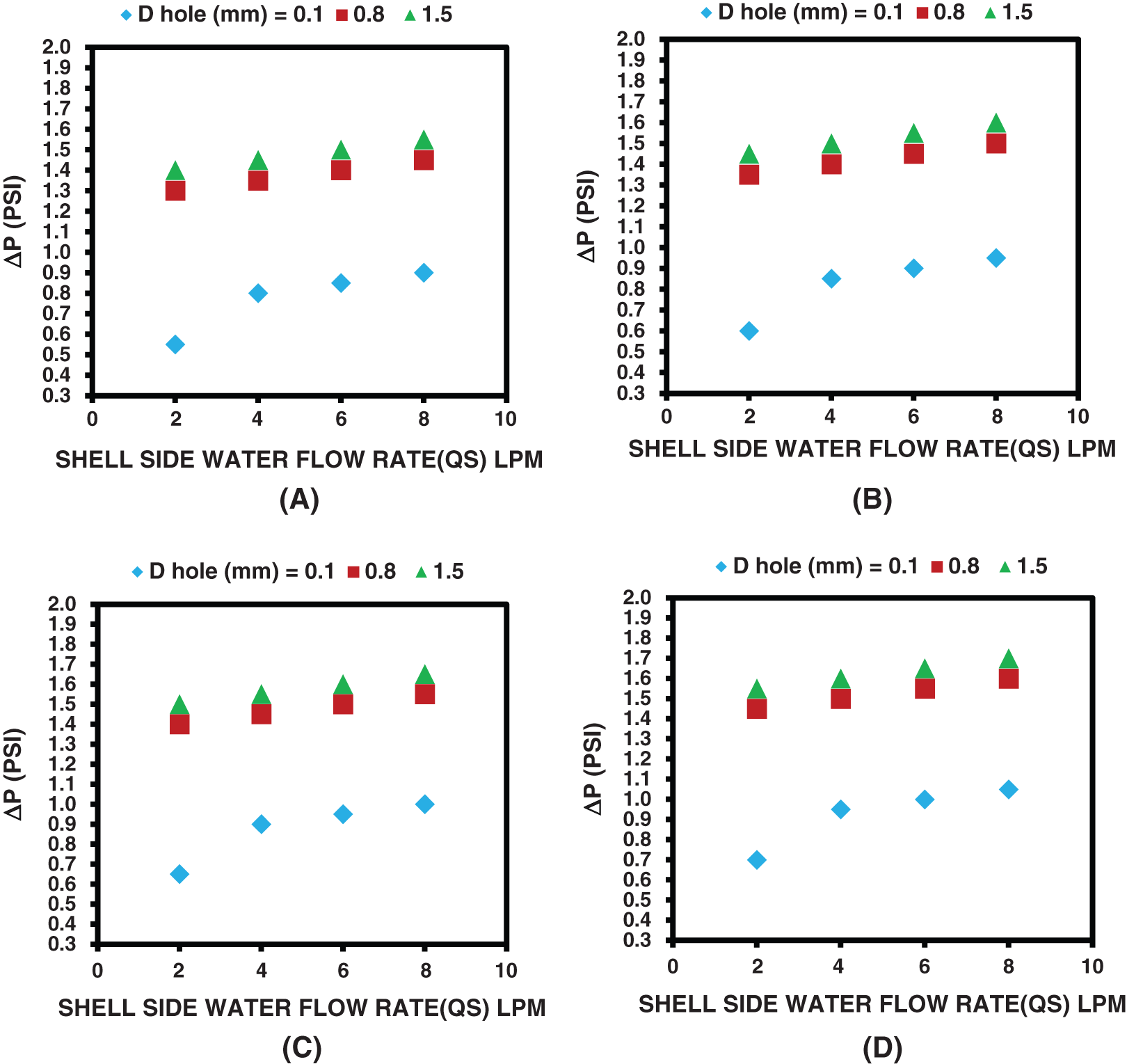
Figure 8: Effect of bubble diameter on the pressure drop for A) Qa = 0.5 LPM, B) Qa = 1 LPM, C) Qa = 1.5 LPM, D) Qa = 2 LPM and ΔT = 20°C
In this paper, the improvement of the thermal performance of a vertical shell and coiled tube heat exchanger due to a small air bubble injection into the shell side was experimentally investigated. The main aim was to assess the bubble size impact, which was not investigated before. To perform the study, three different bubble diameters (0.1, 0.8, and 1.5 mm), constant Qh and four Qs Flow rates, and an invariant number of bubbles (1400), and temperature differences were investigated. The obtained results concluded that, in general, the thermal performance of the heat exchanger was improved with the increase of the shell side flow rate. A significant enhancement in the heat exchanger thermal efficiency was associated with air bubble injection into the shell side of the tested heat exchanger. The higher the airflow rate of injected bubble, the higher enhancement was. Surprisingly, the larger bubble diameter contributed to more improvement in the heat exchanger efficiency. This behavior was very clear at a low airflow rate (Qa < 1.5 LPM) where the bubble size was significantly affected the thermal performance of the heat exchanger. However, the role of bubble size becomes insignificant for small bubble size (bubble diameter of 0.1 and 0.8 mm) with increasing air mass flow rate and ultimately dismissed at air mass flow rate greater or equal to 1.5 LPM. This could be led to conclude that to obtain the optimum heat transfer enhancement using a small bubble size; one must carefully control the injection air flow rate. Nevertheless, this finding needs more experimentation to confirm.
Funding Statement: The authors received no specific funding for this study.
Conflicts of Interest: The authors declare that they have no conflicts of interest to report regarding the present study.
1. Ahmadzadehtalatapeh, M., Yau, H. (2012). Energy conservation potential of heat pipe heat exchanger: Experimental study and predictions. International Journal of Engineering, 25, 193–200. DOI 10.5829/idosi.ije.2012.25.03b.06. [Google Scholar] [CrossRef]
2. Kahrom, M., Haghparast, P., Javadi, S. M. (2010). Optimization of heat transfer enhancement of flat plate based on pereto genetic algorithm. International Journal of Engineering, 23, 177–190. [Google Scholar]
3. Lee, H. S. (2020). Thermal design: heat sinks, thermoelectric, heat pipes, compact heat exchangers, and solar cells. Canada,John Wiley & Sons. [Google Scholar]
4. Moosavi, A., Abbasalizadeh, M., Dizaji, H. S. (2016). Optimization of heat transfer and pressure drop characteristics via air bubble injection inside a shell and coiled tube heat exchanger. experimental. Thermal and Fluid Science, 78, 1–9. DOI 10.1016/j.expthermflusci.2016.05.011. [Google Scholar] [CrossRef]
5. Dizaji, H. S., Jafarmadar, S., Abbasalizadeh, M., Khorasani, S. (2015). Experiments on air bubbles injection into a vertical shell and coiled tube heat exchanger; exergy and NTU analysis. Energy Conversion and Management, 103, 973–980. DOI 10.1016/j.enconman.2015.07.044. [Google Scholar] [CrossRef]
6. Hashemian, M., Jafarmadar, S., Dizaji, H. S. (2016). A comprehensive numerical study on multi-criteria design analyses in a novel form (conical) of double pipe heat exchanger. Applied Thermal Engineering, 102, 1228–1237. DOI 10.1016/j.applthermaleng.2016.04.057. [Google Scholar] [CrossRef]
7. Dizaji, H. S., Khalilarya, S., Jafarmadar, S., Hashemian, M., Khezri, M. (2016). A comprehensive second law analysis for tube-in-tube helically coiled heat exchangers. Experimental Thermal and Fluid Science, 76, 118–125. DOI 10.1016/j.expthermflusci.2016.03.012. [Google Scholar] [CrossRef]
8. Khorasani, S., Dadvand, A. (2017). Effect of air bubble injection on the performance of a horizontal helical shell and coiled tube heat exchanger: An experimental study. Applied Thermal Engineering, 111, 676–683. DOI 10.1016/j.applthermaleng.2016.09.101. [Google Scholar] [CrossRef]
9. Nouri, N. M., Sarreshtehdari, A. (2009). An experimental study on the effect of air bubble injection on the flow-induced rotational hub. Experimental Thermal and Fluid Science, 33, 386–392. DOI 10.1016/j.expthermflusci.2008.09.008. [Google Scholar] [CrossRef]
10. Kitagawa, A., Kosuge, K., Uchida, K., Hagiwara, Y. (2008). Heat transfer enhancement for laminar natural convection along a vertical plate due to sub-millimeter-bubble injection. Experiments in Fluids, 45, 473–484. DOI 10.1007/s00348-008-0490-8. [Google Scholar] [CrossRef]
11. Kitagawa, A., Uchida, K., Hagiwara, Y. (2009). Effects of bubble size on heat transfer enhancement by sub-millimeter bubbles for laminar natural convection along a vertical plate. International Journal of Heat and Fluid Flow, 30, 778–888. DOI 10.1016/j.ijheatfluidflow.2009.02.008. [Google Scholar] [CrossRef]
12. Kitagawa, A., Kimura, K., Hagiwara, Y. (2010). Experimental investigation of water laminar mixed-convection flow with sub-millimeter bubbles in a vertical channel. Experiments in Fluids, 48, 509–519. DOI 10.1007/s00348-009-0757-8. [Google Scholar] [CrossRef]
13. Kitagawa, A., Kitada, K., Hagiwara, Y. (2010). Experimental study on turbulent natural convection heat transfer in water with sub-millimeter-bubble injection. Experiments in Fluids, 49, 613–622. DOI 10.1007/s00348-010-0838-8. [Google Scholar] [CrossRef]
14. Kitagawa, A., Endo, H., Hagiwara, Y. (2011). Effects of sub-millimeter-bubble injection on transition to turbulence in natural convection boundary layer along a vertical plate in water. Experiments in Fluids, 51, 701–710. DOI 10.1007/s00348-011-1089-z. [Google Scholar] [CrossRef]
15. Singh, G., Nandan, A. (2016). Experimental study of heat transfer rate in a shell and tube heat exchanger with air bubble injection. International Journal of Engineering, 29, 1160–1166. [Google Scholar]
16. El-Said, E. M., Abou Alsood, M. M. (2018). Experimental investigation of air injection effect on the performance of a horizontal shell and multi-tube heat exchanger with baffles. Applied Thermal Engineering, 134, 238–247. DOI 10.1016/j.applthermaleng.2018.02.001. [Google Scholar] [CrossRef]
17. Baqir, A. S., Mahood, H. B., Kareem, A. R. (2019). Optimization and evaluation of NTU and effectiveness of a helical coil tube heat exchanger with air injection. Thermal Science and Engineering Progress, 14, 100420. DOI 10.1016/j.tsep.2019.100420. [Google Scholar] [CrossRef]
18. Kreem, A. R., Baqir, A., Mahood, H. B. (2019). Temperature distribution measurements along helical coiled tube heat exchanger with effect of Air injection. International Engineering Conference (IECpp. 85–89Erbil–Iraq. DOI 10.1109/IEC47844.2019.8950586. [Google Scholar] [CrossRef]
19. Hasan, S. S., Baqir, A. S., Mahood, H. B. (2021). Improvement of thermal performance of coiled tube heat exchanger utilizing air bubble injection technique. IOP Conference Series: Earth and Environmental Science, 1–8. [Google Scholar]
20. Shukla, O. P., Yadav, B. K. (2019). CFD analysis on shell and coiled tube heat exchanger for heat transfer augmentation due to air bubbles injection. International Journal of Innovative Research in Technology, 7(9), 256–261. [Google Scholar]
21. Subesh, T., Dilip Raja, N., Logesh, K., Ramesh, V., Venkatasudhahar, M. et al. (2020). Study on performance of horizontal single pass shell and multi-tube heat exchanger with baffles by air bubble injection. International Journal of Ambient Energy, 41, 641–651. DOI 10.1080/01430750.2018.1484808. [Google Scholar] [CrossRef]
22. Ghashim, S. L., Flayh, A. M. (2020). Experimental investigation of heat transfer enhancement in heat exchanger due to air bubbles injection. Journal of King Saud University–Engineering Sciences. DOI 10.1016/j.jksues.2020.06.006. [Google Scholar] [CrossRef]
23. Sokhal, G. S., Dhindsa, G. S., Sokhal, K. S., Ghazvini, M., Sharifpur, M. et al. (2020). Experimental investigation of heat transfer and exergy loss in heat exchanger with air bubble injection technique. Journal of Thermal Analysis and Calorimetry, 28, 1–11. DOI 10.1007/s10973-020-10192-1. [Google Scholar] [CrossRef]
24. Pourhedayat, S., Dizaji, H. S., Jafarmada, S. (2019). Thermal-energetic behavior of a vertical double-tube heat exchanger with bubble injection. Experimental Heat Transfer, 32, 455–468. DOI 10.1080/08916152.2018.1540504. [Google Scholar] [CrossRef]
25. Panahi, D. (2017). Evaluation of nusselt number and effectiveness for a vertical shell-coiled tube heat exchanger with air bubble injection into shell side. Experimental Heat Transfer, 30, 179–191. DOI 10.1080/08916152.2016.1233145. [Google Scholar] [CrossRef]
 | This work is licensed under a Creative Commons Attribution 4.0 International License, which permits unrestricted use, distribution, and reproduction in any medium, provided the original work is properly cited. |