| Energy Engineering |
DOI: 10.32604/EE.2021.016357
ARTICLE
Analysis of Near-Wake Deflection Characteristics of Horizontal Axis Wind Turbine Tower under Yaw State
1School of Energy and Power Engineering, Inner Mongolia University of Technology, Hohhot, 010051, China
2Key Laboratory of Wind Energy and Solar Energy Utilization Technology, Ministry of Education, Inner Mongolia University of Technology, Hohhot, 010051, China
3School of Mechanical Engineering, Inner Mongolia University of Technology, Hohhot, 010051, China
*Corresponding Author: Jianwen Wang. Email: wangjianwen@imut.edu.cn
Received: 01 March 2021; Accepted: 15 July 2021
Abstract: The yaw of the horizontal axis wind turbine results in the deflection of the wake flow field of the tower. The reasonable layout of wind farm can reduce the power loss of the downstream wind turbine generators due to the blocking effect of the upstream wake flow and increase the output power of the whole wind farm. However, there is still much space for further research. In this paper, experimental research is conducted on the near-wake deflection characteristics of wind turbine tower under yaw state, expecting the effect of throwing away a brick in order to get a gem. In the low-turbulence wind tunnel test, regarding the most unfavorable position where the rotating blades coincide with the tower, Particle image velocimetry (PIV) technology is used to test the instantaneous velocity field and output power and analyze experimental data at four different yaw angles, different inflow velocities and heights. Meanwhile, in order to quantitatively analyze the laws on wake deflection, the radon transformation is used to analyze the velocity contour for calculating the wake direction angle, and the results show high reliability. The comprehensive experimental results indicate that the near-wake flow field of the tower obviously deflects towards a side in the horizontal plane. With the increase of the yaw angle, the deflection angle of the wake flow field further increases, and the recovery of wake velocity accelerates. The closer to the blade root, the more complex the flow is, and the influence of the blade on the near wake of the tower is gradually weakened. The change laws on the wake direction angle with the yaw angle and the blade spanwise direction are obtained. The experiment in this paper can provide guidance for layout optimization of wind farm, and the obtained data can provide a scientific basis for the research on performance prediction of horizontal axis wind turbine.
Keywords: Horizontal axis wind turbine; yaw; tower; near-wake
The distance between the upstream wind turbine and the downstream tower is relatively small in horizontal axis wind turbines. Thus, the rotary/static interference effects between the blades and the tower of the upwind horizontal axis wind turbines are considerable [1]. Disturbance of the upstream blade wakes on the downstream tower modifies the flow characteristics around the tower. Hence, the wind speed and the flow field in the local area around the tower are significantly influenced, thus affecting the operating efficiency of downstream wind turbines. Previous studies [2–4] demonstrated that the aerodynamic tower performance is most unfavorable when the blades completely shield the tower. This is of particular importance in the shutdown state, which is characterized by high wind speeds. Thus, the flow around the tower is significantly alerted when blades are in different positions, which affects the aerodynamic force and wind-induced response of the tower itself. In addition, in the actual working environment of the wind turbine, the wind direction continuously changes. In comparison, the yaw system wind turbine speed is relatively slow. Therefore, the rotating shaft of wind turbine vane wheel cannot be timely aligned with the direction of the incoming wind. As a result, the yaw state of the wind turbine is a very common operating mode [5,6], and different yaw states will lead to the fluctuation of output power and change wake characteristics of the tower [7–9]. Therefore, it is of great engineering significance to the study on the wake characteristics of the wind turbine tower under yaw condition.
In recent years, many researchers have investigated the interaction between the blades, the wind turbine tower, and its wake characteristics. Ren et al. investigated the interference effect on the wind turbine blades and tower wakes based on CFD method [10]. Wen et al. analyzed power fluctuation and losses due to wind shear and tower shadow for NREL 5 MW baseline wind turbine with blade element momentum (BEM) theory [11] and carried out a large number of experimental studies on the load characteristics of wind turbine tower under yaw [12]. Cao et al. [1] employed two-dimensional Navier-Stokes (N-S) equations to study the interference effect of the upstream blade wakes on the downstream tower, finding that when the tower was near the blade wake, there was a strong mutual-interference, and this interference altered the flow symmetry around the tower cylinder. Zhang et al. revealed the influence law of wind azimuths on generated power of wind turbines placed in serial configuration. Numerical simulation was combined with theoretical analysis to investigate the change rule of horizontal axis wind turbine wake under yaw operating conditions [13–14]. Wake shift effect and its influence on downstream wind turbines were investigated. Liao et al. simulated two full-scale 5 MW wind turbines with serial arrangement by unsteady CFD method [15–16] and studied the flow mechanism of wake offset control and its influence on the downstream wind turbine. Ke et al. studied a five MW wind turbine tower-blade system in [17] Large eddy simulation method (LES). Furthermore, contrastive analysis was conducted on the influence of different yaw angles on mean surface wind pressure, fluctuating wind pressure, lift coefficient, drag coefficient, and flow characteristics around the tower and the wake.
Existing studies have mainly focused on the flow around the blades, the unsteady interference between the tower and the blades, and numerical simulation of flow field characteristics of wind turbine wake under yaw state. However, few systematic discussions regarding yaw angle influence on the flow field around the tower of the wind turbine exist. Furthermore, there are even fewer experimental studies. In this paper, a small horizontal axis wind turbine is studied via PIV technique in a low turbulence wind tunnel. Experimental study on the tower near-wake flow field is conducted for the most unfavorable position of a test blade at four different yaw angles and various test heights. By analyzing the experimental data, the yaw angle influence rule of the tower near-wake flow field is discussed. Furthermore, skew angles of tower wakes under different yaw angles are obtained by applying digital image processing technology to the analysis of the velocity contours.
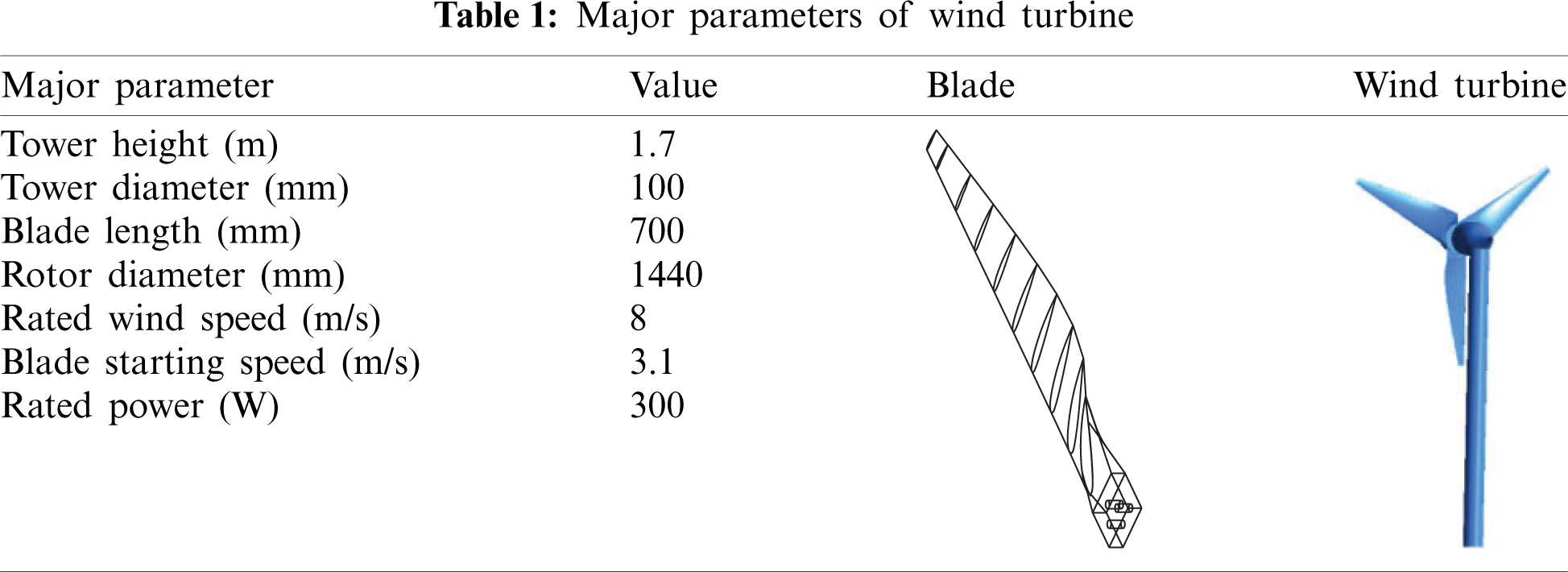
Experiments were conducted in the open section of B1/K2 direct-action low-speed wind tunnel. The wind tunnel is composed of power section, rectification section, contraction section, closed test section, diffusion section, and open test section. The total length of the wind tunnel is 24.59 m, and the diameter of the open test section is 2.04 m. Maximum stable wind speed is 20 m/s, digital down converter technology is used for wind speed adjustment. The wind turbine is novel S airfoil profile 3-blade horizontal axis wind turbine. The main parameters are listed in Tab. 1.
The flow field measurement is performed through the PIV system produced by LaVision from Germany, which includes:
1) YLF LDY 300 high repetition rate laser, with the maximum output power of 150 W and pulse width of 100 ns. Energy of a single laser beam at the trigger frequency of 15 Hz is 30 mJ, and the output wave-length is 527 nm.
2) Imaging system: High Speed Star 8 high sensitivity and megapixel resolution CCD camera, with the sampling frequency of 15 Hz.
3) VZ11-1032 synchronous controller, which simultaneously controls timing signals of the high-speed camera, the laser, and the image acquisition and processing software to ensure the synchronized triggering of all systems. The rotational speed of the rotor is adjusted via resistive load, while NORMA5000 power analyzer from Fluke is used to monitor the operating parameters, such as the output power and the rotational speed.
Adjustment of the wind turbine blades yaw angle is implemented by controlling a dynamic yaw rotary platform of the small wind turbine. The rotary platform was independently developed by the research group, and its outline structure is shown in Fig. 1. On this platform, TP3340 motion controller is used to control the position, while precise control of the yaw angle is achieved via high inertia MDMF302L1H6 M servo motor, acting as the motion actuator.
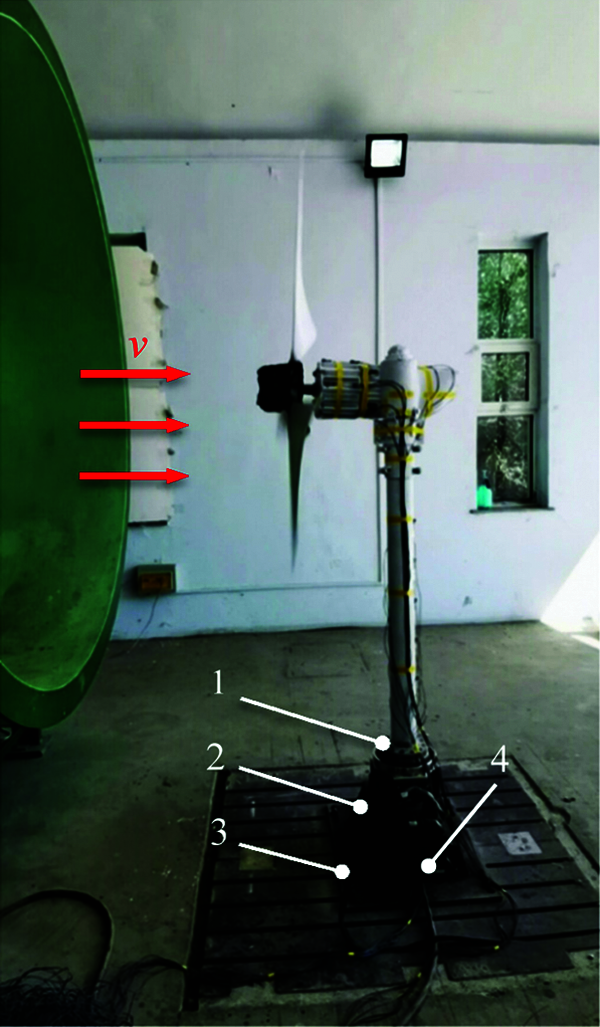
Figure 1: Dynamic yaw bench of miniature wind turbine: 1. Model of small wind turbine, 2. Rotating platform, 3. Base, 4. Servo motor
The yaw angle γ of the wind turbine is defined as the angle between the incoming flow and the rotating shaft of the wind turbine, as demonstrated in Fig. 2a. The wind tunnel offers stable incoming flow with fixed flow direction and adjustable velocity. Therefore, during experimental investigations, the yaw working conditions of the small wind turbine are implemented by fixing the wind direction of the incoming flow and rotating the wind turbine as demonstrated in Fig. 2b.
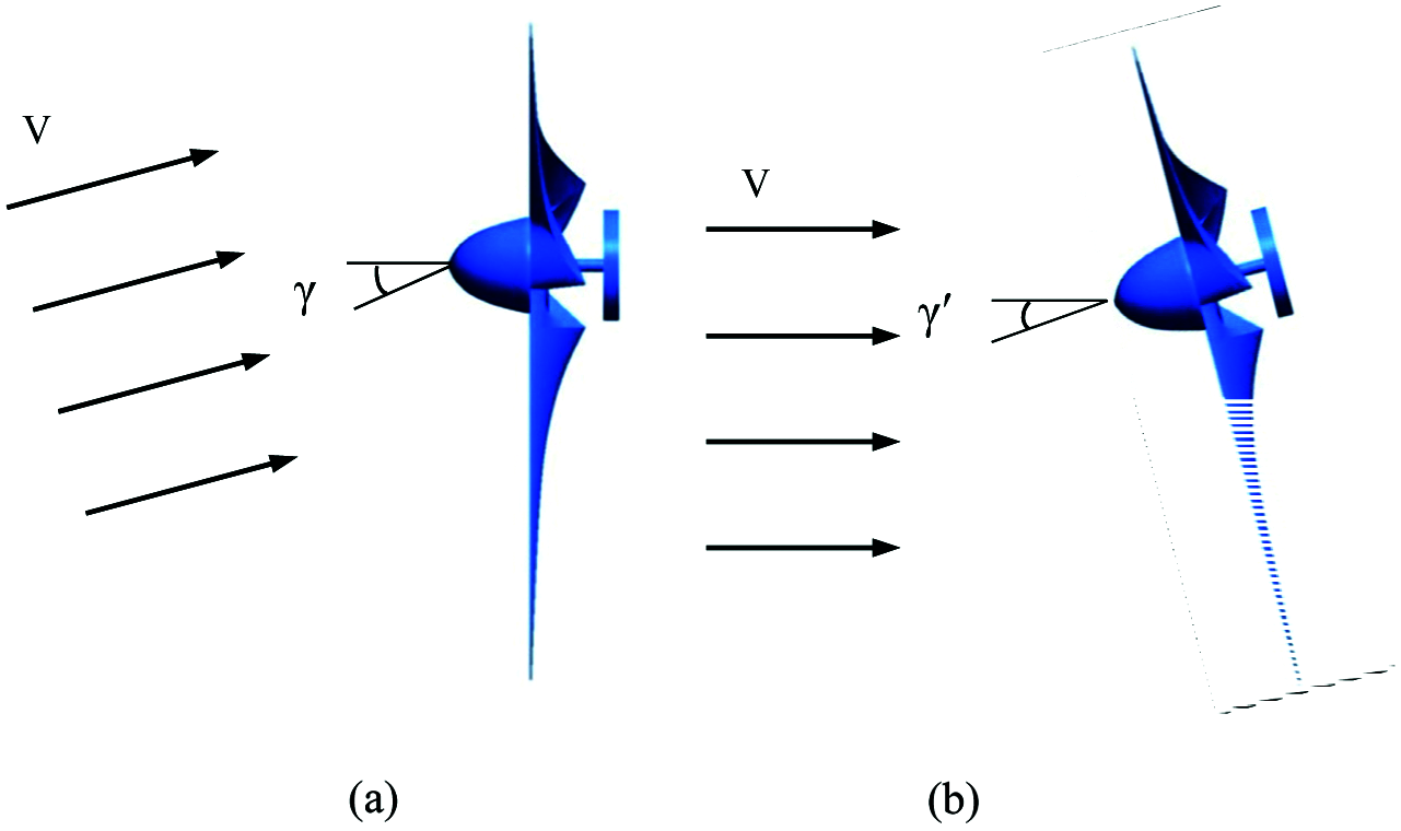
Figure 2: Diagram of the yaw angle from above: (a) Yaw angle of wind turbine, (b) Experimental simulation of yaw angle
During experimental investigation, the wind turbine was placed in a jet stable region of the wind tunnel opening section, and the influence of blockage ratio could not be considered. The turbulence intensity under the experimental wind speed was less than 1.4%. The blades on the rotor rotate in the counterclockwise direction. The flow field measurement experiment is carried out when the test blade is at the most unfavorable position, i.e., when the blade is overlapped with the tower. Driven by the dynamic yaw rotating platform, the small wind turbine rotates counterclockwise to adjust the yaw angle. PIV technique is used to study the effect of different yaw angles on the near-wake flow field of wind turbine tower under multiple working conditions.
The following working condition parameters are employed in the experiments. Yaw angle γ is 0°, 10°, 20°, or 30°. Incoming flow velocity V is 6, 7, 8, or 9 m/s, while the blade tip speed ratio λ is equal to 4.5, 5, 5.5, or 6. The measurement area is located in the near-wake flow field directly behind the tower. It is tangent to the tower and is spanned toward four spanwise height planes of 0.3, 0.4, 0.5 and 0.6R (defined as 1, 2, 3 and 4# planes) along the test blade. The shooting area has the size of 200 mm × 200 mm. The PIV measurement area and coordinate system are shown in Fig. 3. The direction of the tower is defined as z-axis, with the upward direction defined as positive; the x-y plane is the plane where the base is located, which is perpendicular to the tower. The horizontal inflow direction is defined as the positive direction of the x-axis, and the positive direction of the y-axis is consistent with the rotation direction of the wind wheel. The central axis of the tower is located at y = 100 mm, and the size of the imaging area is 200 mm × 200 mm. The measured area and PIV coordinates are shown in Fig. 3. The z-axis represents the centerline of the tower, with the upward direction defined as positive. Plane x-y is parallel to the tower base, while its normal vector is aligned with the tower. The direction of horizontal incoming flow is defined as the positive direction of x-axis. The positive direction of y-axis is consistent with the rotational direction of the rotor.
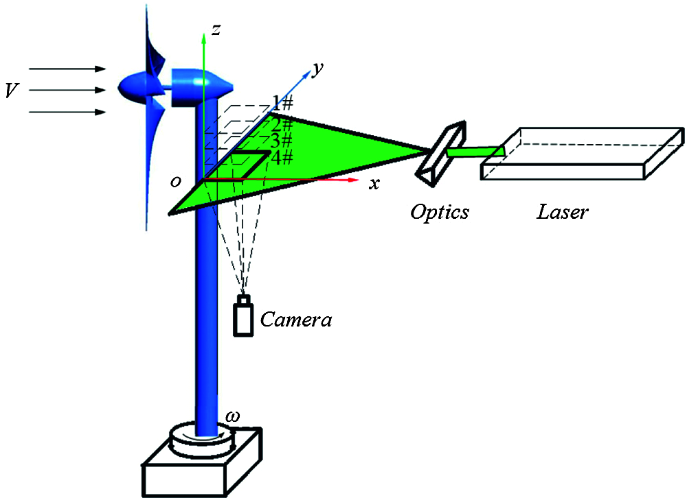
Figure 3: Schematic representation of PIV measurement region
In order to measure the tower flow field during the most unfavorable blade position, it is necessary to accurately determine whether the blades interact with the right front of the tower and transmit the Boolean signal to the tachometer and the PIV system to achieve synchronous acquisition or control. More specifically, the following method is applied. Synchronous trigger device and rotational speed measuring device are designed for the acquisition of rotor speed and pulse signal of phase-locked positioning. Then, diffusion photoelectric sensor is mounted on the turbine side generator behind the rotor, thus adhering reflecting material to the predetermined circumferential trigger positions on the suction side of the wind turbine rotary blades. When the test blade rotates to the location directly in front of the tower, i.e., the location where the blade is heading straightly downwards, it is set as the triggering position. The photoelectric sensor receives an abrupt optical signal, which is then converted into pulse signal and transmitted to the tachometer to measure the rotational speed of the wind turbine. This signal is also utilized as the external trigger signal for the PIV measurement system synchronizer to control the initiation of camera photographing, thus ensuring the PIV measurement system start of data acquisition. In the experiments, the cabin surfaces are painted with black flat paint to reduce the effect of light reflection on the measurement results.
4 Experimental Results and Analysis
4.1 Effects of Yaw Angle on the Output Power of the Wind Turbine
The different yaw angle relative to the direction of incoming flow has an important influence on the output power and load of the wind turbine. The maximum output power of the wind turbine with a yaw angle can be extracted as:
ρ is the density of the air, Ar is the swept area of the rotor, V0 is the free stream wind speed and Cp is the power coefficient, γ is the yaw angle of the turbine. k is constant exponent term, has been estimated experimentally in different studies. In literature, power loss due to yaw misalignment is typically defined as being proportional to a factor of coskγ [18]. In uniform flow conditions, k = 3. However, measurements and simulations show that the value of k varies for unsteady wind speeds. Different studies have found the k parameter ranging from k = 1.8 to k = 5.14 [19], depending on atmospheric and turbine operational condition.
Apart from having an impact on the power production, the yaw alignment of a horizontal axis wind turbine also affects the loads induced on the tower. The blades of a horizontal axis wind turbine operating with a yaw error will experience variations of angles of attack and relative velocities. The varying angles of attack and relative velocities give rise to azimuthal load variations. However, only the effect of yaw angle on the power production is analyzed in this study. A study of azimuthal load variations due to yaw angle can be found in Wen et al. [20].
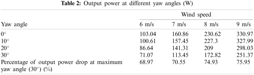
In this experiment, following the modification of the yaw angle, the power data are sampled in 60 s, while PIV technology was used to test the flow field data, with the mean value representing the output power of the wind turbine. For the incoming wind speed of 6, 7, 8, and 9 m/s, power outputs at different yaw angles are listed in Tab. 2. As indicated by the results, when the yaw angle is increased, the power output is steadily decreased. By comparing the power data for the incoming wind speed of 8 m/s, starting from the yaw angle γ = 0° up to γ = 30°, each increase of the yaw angle increment by 10° results in a decline of the power output by 1.44%, 8.05%, and 17.31%, respectively. This tendency of power loss is also confirmed by the wind speeds of 6, 7, and 9 m/s. When the yaw angle increases from 0° to 30° and the incoming wind speed increases from 6 to 9 m/s, the output power falls to 68.97%, 70.55%, 74.93%, and 75.95% of that under the axial flow condition, respectively. This demonstrates that the power loss increases with the yaw angle. The power decreases between cos2 γ and cos3 γ during yaw, and the power loss law is similar to cos3 γ when the incoming wind speed is greater than or equal to the rated wind speed. This result also validated the credibility of the experiment.
4.2 Experimental Velocity Field Measurement on Planes with Different Blade Heights
When the velocity of the incoming flow is v = 7 m/s, the blade tip speed ratio is λ = 5 and the yaw angle is γ = 10°, the velocity fields on four planes numbered 1# to 4# are measured. The resultant axial velocity contours of the tower wake flow are depicted in Fig. 4. In order to highlight the proportional relationship between the tower and the measuring area, horizontal and vertical axes are standardized by dividing them by the radius of the tower, which are expressed as Cx and Cy. Owing to the blades obstruction on the tower and the rotation effect of the rotor, the wake flow of the tower demonstrates conspicuous change. After the incoming flow passes through the tower, the area with low-speed stationary the stream with some velocity deficit is formed close to the back of the tower. When a blade rotates around the location in front of the tower, change of stagnation point location is induced at the leading edge. Therefore, the tower wake deflects and the flow on one side of the tower is accelerated. This leads to asymmetry of the cylinder bypass flow in the near-wake flow field of the tower. Since the experimental rotor rotates counterclockwise, the tower wake deflects towards the right side, i.e., towards the positive direction of the y-axis in the velocity contours.
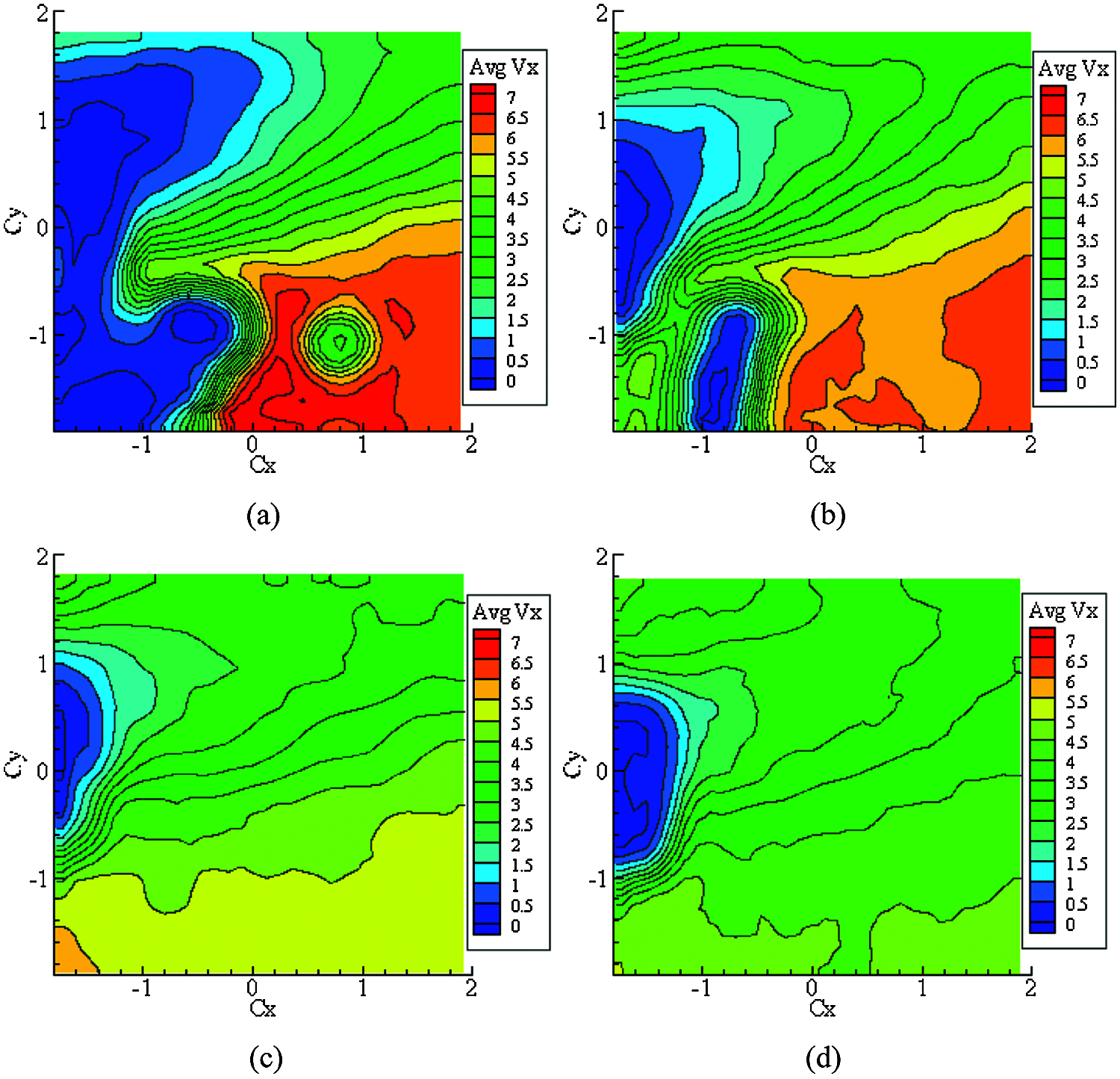
Figure 4: Axial velocity contour of the tower near-wake flow at different spanwise heights for γ = 10° and v = 7 m/s (a) 1# (b) 2# (c) 3# (d) 4#
From blade height planes 1# to 4#, near-wake deflection degree of the tower shows a gradual decrease trend, and the flow is eventually stabilized. This is due to a decrease in the chord length of the blade profile, while simultaneously increasing the torsional angle of the blade when moving from the blade root to its tip. Blade obstructing effect on the incoming flow decreases, while effects of the incoming flow bypassing the blades on the near-wake flow field of the tower decline. Thus, the deflection degree of the wake is reduced. The closer it is to the blade root, the more significant the influence of the blade on the near-wake flow field of the tower. With the increase of the blade height, this effect gradually decreases. Meanwhile, due to a disturbance of the upstream blades, the incoming flow, passing through the blades, attaches to the tower. Then, it bypasses the tower and flows to the leeside of the tower, thus forming complicated flow eddies of a certain scale that are located near the blade root. On plane 1#, small-scale eddies are captured.
4.3 Experimental Measurement of Wake Flow Fields at Different Yaw Angles
4.3.1 Effects of Yaw Angle on Tower Wake Flow Fields
When the incoming flow is v = 7 m/s, the blade tip speed ratio is equal to λ = 5, and the yaw angle is equal to γ = 0°, 10°, 20° and 30°. For these parameters, the mean resultant velocity contour on plane 3# is presented in Fig. 5. By comparing the results, the near-wake flow field behind the tower shows certain velocity deficit. Furthermore, when the yaw angle is 0° and the blade is in the most unfavorable position, the mutual interference between the tower and the blades is most remarkable and the velocity deficit of the wake is most critical. When the yaw angle is relatively small, the obstructing effect of the blades is distinct. With an increase in the yaw angle, blade effect on the tower wake is decreased, and the recovery of wake velocity is significantly accelerated.
Mean axial velocity contour of the wake flow field in the front section of the tower, shown in Fig. 5, is quantitatively analyzed. Straight line Cy = 0 is taken as the monitoring location (i.e., radial location of the tower). Data points are extracted at a constant interval to depict the variation curve for mean resultant velocities at four different yaw angles, as shown in Fig. 6. With an increase in the yaw angle, both the shift degree and the recovery speed of the wake towards the positive direction of y-axis are rising. Furthermore, the tower effect on wake velocity is significantly weakened. By extracting the data at Cx = 0 in Fig. 6a, when yaw angle increases from 0° to 30°, the wind speeds of the corresponding points recover to 35.71%, 55.14%, 79.71%, and 89.86% of the incoming wind speed, respectively. By comparing radial velocity data of three different planes in Fig. 6, from 1# plane to 3# plane, the closer it is to the blade tip, the faster the wake recovery. At γ = 30°, steady flow is gradually restored in the shooting area.
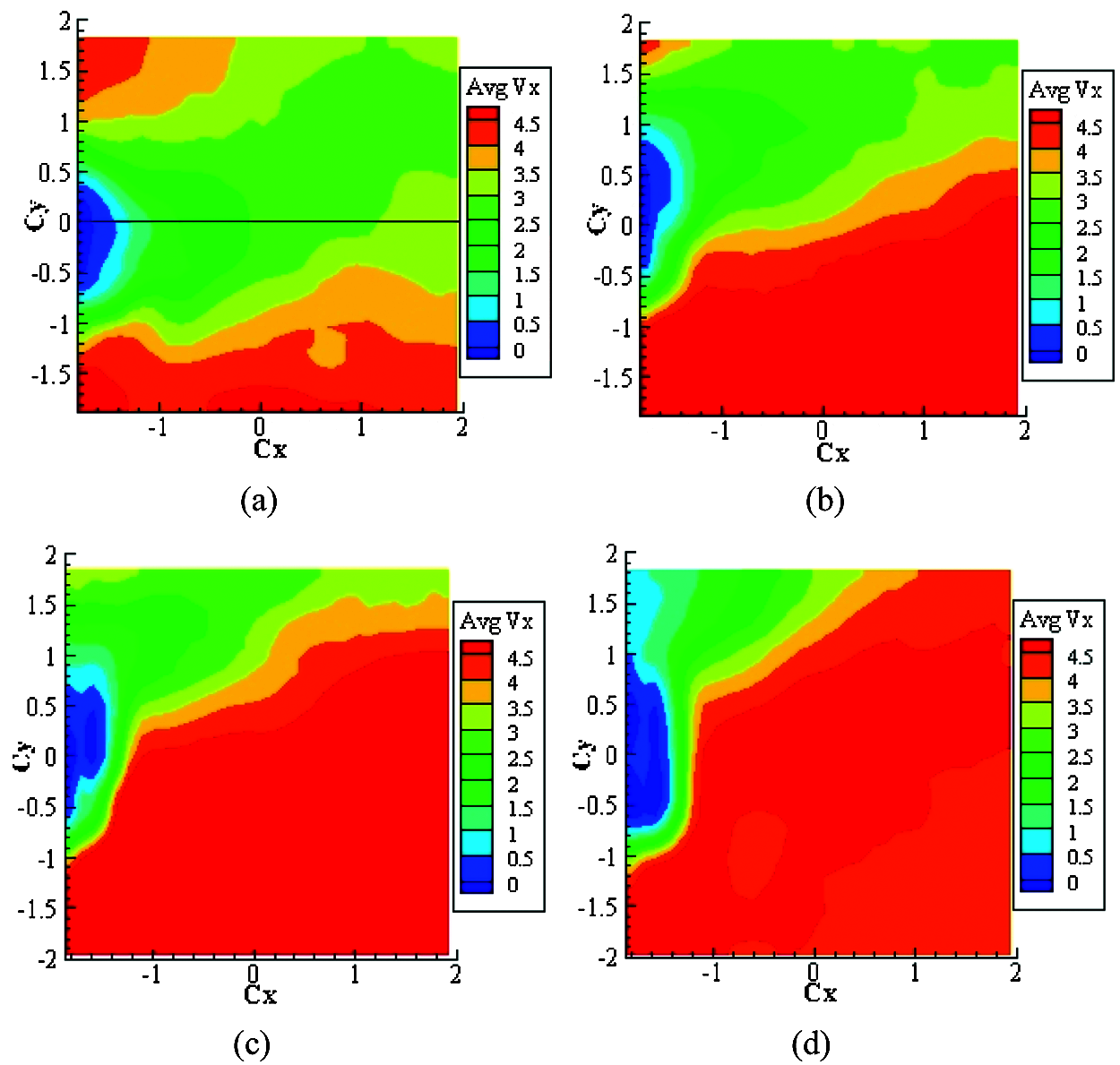
Figure 5: Mean axial velocity contour at different yaw angles (a)
4.3.2 Analysis of Wake Deflection Laws
According to the velocity contours obtained in the above-mentioned experiments, the wake is inevitably deflected along the direction of the incoming flow to some extent. Furthermore, the wake direction changes with the variation of yaw angle. Radon transform is employed to analyze the velocity contour and calculate the skew angle (denoted by β) of the wake. When the wake is parallel to the x-axis, β = 0°. When the wake is deflected to the positive side of the y-axis, β is positive.
Size of experimentally obtained PIV velocity field contours is 1024 × 1024 pixels, as shown in Fig. 7a. First, the velocity field contour data are normalized to the range of 0–1. In this paper, the velocity point cloud distribution in the range from 0.7 to 0.8 are used to evaluate the wake direction. For the convenience of direction estimation, it is necessary to quantify the contours. In normalized velocity field contours, three curves corresponding to values of 0.7 ± d, 0.75 ± d, and 0.8 ± d are extracted (Fig. 7b). By controlling the value of d, which is chosen as d = 0.002 in this paper, the width of the curve can be adjusted. Almost none of the velocity field contours show a strict linear distribution of wakes. Hence, the traditional linear direction estimation algorithm cannot be used to calculate the wake direction. In this paper, Fig. 7b is regarded as a digital image, and Radon transformation [21] is introduced to estimate the angle between the longest approximate straight-line segment and the x-axis, which is regarded as the calculation result of the wake skew angle.

Figure 6: Mean axial velocity at the radial position of the tower (Cy = 0) (a) 1# (b) 2# (c) 3#
Radon transform of image f (x, y) along the random direction represents the gray projection of the image of the specific direction. Its mathematical expression can be written as:
Radon transform results of Fig. 7b are shown in Fig. 7c, where the three brightest spots correspond to approximately linear segments of three curves in Fig. 7b. By extracting the abscissa of each of the three brightest spots and subtracting 90°, the average wake deflection angle β relative to the direction of the incoming wind speed in the measured area can be obtained.
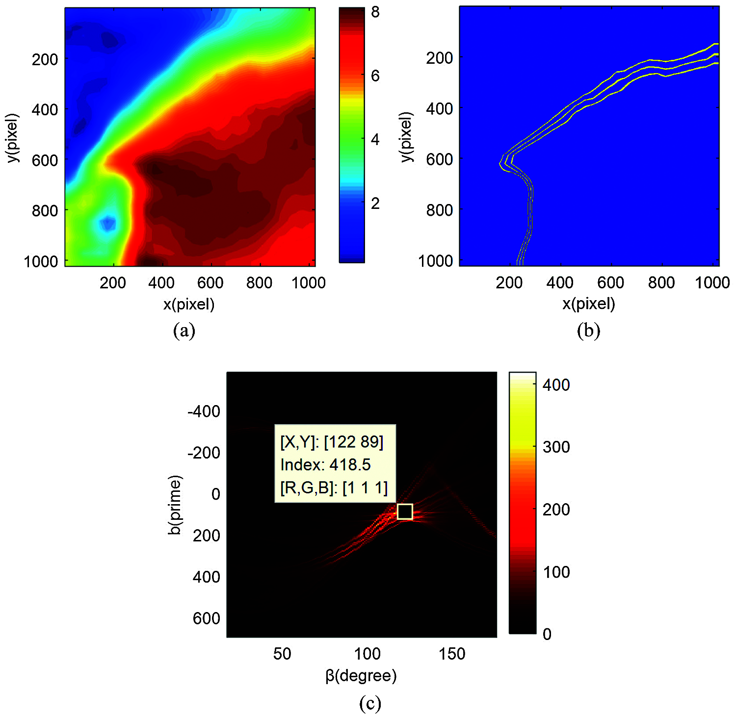
Figure 7: Result of main direction discrimination, γ= 20: (a) Velocity contour, (b) Main direction extraction of wake, (c) Radon transform (Wake direction determination)
Wake skew angles at incoming wind speed of v = 7 m/s on four planes 1# to 4# of different blade heights and at four different yaw angles are calculated. The results are presented in Fig. 8. According to the calculation results, if plane 3# (blade height of 0.5R) is omitted during the process of yaw angle γ increasing from 0° to 30°, the deflection angle of the wake gradually increases and it is always greater than the yaw angle. Degree of the wake deflection varies on planes with different blade heights, e.g., wake skew angles are 41°, 43° and 46° for γ = 30°. Nevertheless, wake deflection rule on plane 3# is slightly different from that on the remaining three planes. This is caused by the local effect on the leeside of the tower induced by vortex systems of different scales in wakes of upstream blades. The results can play a guiding role in optimizing the layout of downstream wind turbine generators and improving the overall output power of wind farms. In the experiment, due to the limitations of PIV shooting area, no complete and reliable changes of vortex system structure are captured. In future works, researchers can consider expanding the shooting area, and collecting the full field information on the near wake of the tower to further explore the change laws of complex wake flow at the leeward side of the tower.
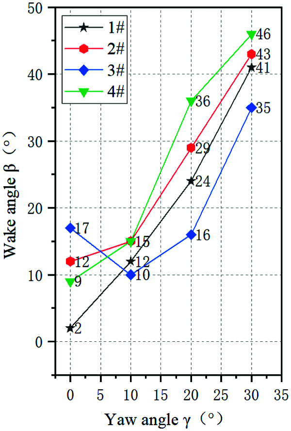
Figure 8: Calculation results of wake skew angles at different yaw angles
Particle image velocimetry (PIV) experiments are carried out on the near-wake flow field of the small horizontal axis wind turbine tower at four yaw angles and four different test heights. the output power , structural change of the wake flow field , and the change rule of wake skew angle at different yaw angles are compared and analyzed. The following conclusions are drawn:
(1) Experimental investigation of yaw angle effects on the power output of wind turbine is conducted. Compared with the axial flow condition, the power of the experimental wind turbine decreases between cos2 γ and cos3 γ during yaw, and the power loss law is similar to cos3 γ when the incoming wind speed is greater than or equal to the rated wind speed.
(2) According to the results for the yaw angle of γ = 10°, when the blade is at the location with the greatest influence on the wake flow of the tower, under the rotation effect of rotor and the interference caused by the upstream blades, the stagnation point position of the tower upwind side leading edge changes. Near-wake flow field is deflected to the side and subjected to asymmetric distribution relative to the centerline plane of the tower. Furthermore, the closer to the height plane of the blade root, the more complex the wake flow of the tower is. Moreover, more significant the influence of the blade on the near wake of the tower.
(3) With an increase in the yaw angle, the deflection degree of near-wake towards the positive direction of y-axis and the recovery speed are both accelerated. Furthermore, the tower influence on the wake flow velocity is significantly weakened. To quantitatively analyze the deflection law of the wake, Radon transformation is employed to calculate the wake skew angle. The calculation results are scientific and reliable, the method has good robustness, it is relatively easy to implement and has a high degree of automation.
Revelation of the change laws on the near-wake direction angle of the tower under yaw state can provide theoretical guidance for optimizing the layout of downstream wind turbine generators. However, due to the limitation of PIV shooting area and sampling frequency in this experiment, complete and reliable structural changes of wake vortex system were not captured. In future research, the splicing technology can be used to expand the shooting area, collect the full field information on the near wake of the tower, and further explore the complex change laws of wake flow on the leeward side of the tower.
Funding Statement: This work was Supported by the National Natural Science Foundation of China (No. 51766014) and the Natural Science Foundation of Inner Mongolia Autonomous Region (Nos. 2019MS05024, 2020LH06002).
Conflicts of Interest: The authors declare that they have no conflicts of interest to report regarding the present study.
1. Cao, R. J., Hu, J. (2006). Flow interaction between HAWT rotor wake and downstream circular tower. Acta Energiae Solaris Sinica, 27(4), 326–330. DOI 10.3321/j.issn:0254-0096.2006.04.002. [Google Scholar] [CrossRef]
2. Zhang, L. T., Guo, L. F., Rong, Q. (2020). Single parameter sensitivity analysis of Ply parameters on structural performance of wind turbine blade. Energy Engineering, 117(4), 196–207. DOI 10.32604/EE.2020.010617. [Google Scholar] [CrossRef]
3. Wang, Q., Zhou, H., Wan, D. L. (2012). Numerical simulation of wind turbine blade-tower interaction. Journal of Marine Science and Application, 11(3), 321–327. DOI 10.1007/s11804-012-1139-9. [Google Scholar] [CrossRef]
4. Ke, S. T., Yu, W., Wang, T. G., Zhao, L., Ge, Y. J. (2016). Wind loads and load-effects of large-scale wind turbine tower with different halt positions of blade. Wind and Structures, 23(6), 559–575. DOI 10.12989/was.2016.23.6.559. [Google Scholar] [CrossRef]
5. Jeong, M. S., Kim, S. W., Lee, I., Yoo, S. J., Park, K. C. (2013). The impact of yaw error on aeroelastic characteristics of a horizontal axis wind turbine blade. Renewable Energy, 60(5), 256–268. DOI 10.1016/j.renene.2013.05.014. [Google Scholar] [CrossRef]
6. Zhang, S. W., Huang, L. X., Song, D. R., Xu, K., Song, X. P. (2021). Model predictive Yaw control using fuzzy-deduced weighting factor for large-scale wind turbines. Energy Engineering, 118(2), 237–250. DOI 10.32604/EE.2021.014269. [Google Scholar] [CrossRef]
7. Majid, B., Fernando, P. A. (2016). Experimental and theoretical study of wind turbine wakes in yawed conditions. Journal of Fluid Mechanics, 806, 506–541. DOI 10.1017/jfm.2016.595. [Google Scholar] [CrossRef]
8. Mühle, F., Schottler, J., Bartl, J., Futrzynski, R., Evans, S. et al. (2018). Blind test comparison on the wake behind a yawed wind turbine. Wind Energy Science, 3(2), 883–903. DOI 10.5194/wes-3-883-2018. [Google Scholar] [CrossRef]
9. Schottler, J., Bartl, J., Mühle, F., Stran, L., Hlling, M. (2018). Wind tunnel experiments on wind turbine wakes in yaw: Redefining the wake width. Wind Energy Science Discussions, 3(1), 257–273. DOI 10.5194/wes-2017-58. [Google Scholar] [CrossRef]
10. Ren, N., Ou, J. (2009). Aerodynamic interference effect between large wind turbine blade and tower. Computational structural engineering. Springer Netherlands. [Google Scholar]
11. Wen, B. R., Wei, S., Wei, K. X., Yang, W. X., Peng, Z. K. et al. (2018). Influences of wind shear and tower shadow on the power output of wind turbine. Journal of Mechanical Engineering, 54(10), 124–132. DOI 10.3901/JME.2018.10.124. [Google Scholar] [CrossRef]
12. Wen, B. R., Tian, X. L., Dong, X. J., Peng, Z. K., Zhang, W. M. et al. (2019). A numerical study on the angle of attack to the blade of a horizontal-axis offshore floating wind turbine under static and dynamic yawed conditions. Energy, 168, 1138–1156. DOI 10.1016/j.energy.2018.11.082. [Google Scholar] [CrossRef]
13. Li, D. Y., Zhang, L. R., Wang, J. W., Yu, T. T., Lu, C. (2018). Effect on the wake of horizontal axis wind turbine under yaw condition. Renewable Energy Resources, 36(1), 105–110. DOI 10.13941/j.cnki.21-1469/tk.2018.01.016. [Google Scholar] [CrossRef]
14. Guo, M. F., Zhang, L. R., Li, D. Y., Wang, X. L., Niu, J. J. (2020). Analysis on wake deviation and turbulence characteristics of horizontal-axis wind turbine under yawed condition. Journal of Drainage and Irrigation Machinery Engineering, 38(7), 702–707. DOI 10.3969/j.issn.1674-8530.18.0273. [Google Scholar] [CrossRef]
15. Liao, W. P., Li, C., Yang, J. (2017). Investigation on flow mechanism of a wind farm based on yawed wind turbine using wake deflection control strategy. Journal of Chinese Society of Power Engineering, 37(8), 655–662. DOI 10.3969/j.issn.1674-7607.2017.08.010. [Google Scholar] [CrossRef]
16. Liao, W. P., Li, C., Yang, J. (2018). Characteristics of a yawed wake and its influence on downstream wind turbine. Acta Energiae Solaris Sinica, 39(9), 2462–2469. DOI CNKI:SUN:TYLX.0.2018-09-012. [Google Scholar]
17. Wang, X. H., Ke, S. T. (2017). Study on aerodynamic performances of large wind turbine towers considering yaw and blade interferences. Proceedings of the Chinese Society for Electrical Engineering, 38(15), 4546–4554+4655. DOI 10.13334/j.0258-8013.pcsee.171561. [Google Scholar] [CrossRef]
18. Kragh, K. A., Hansen, M. H. (2015). Potential of power gain with improved yaw alignment. Wind Energy, 18(6), 979–989. DOI 10.1002/we.1739. [Google Scholar] [CrossRef]
19. Madsen, H. A., Srensen, N. N., Schreck, S. (2003). Yaw aerodynamics analyzed with three codes in comparison with experiment. 41st Aerospace Sciences Meeting and Exhibit, Reno, Nevada. [Google Scholar]
20. Wen, B. R., Li, Z. L., Jiang, Z. H., Peng, Z. K., Dong, X. J. et al. (2020). Experimental study on the tower loading characteristics of a floating wind turbine based on wave basin model tests. Journal of Wind Engineering and Industrial Aerodynamics, 207. DOI 10.1016/j.jweia.2020.104390. [Google Scholar] [CrossRef]
21. Bai, F. Z., Zhang, T. Y., Gao, X. J., Xu, Y. X. (2018). Local bending measurement of laser stripe images based on Fourier-polar transformation. Acta Optica Sinica, 38(8), 197–203. DOI 10.3788/AOS201838.0815019. [Google Scholar] [CrossRef]
 | This work is licensed under a Creative Commons Attribution 4.0 International License, which permits unrestricted use, distribution, and reproduction in any medium, provided the original work is properly cited. |