| Energy Engineering |
DOI: 10.32604/EE.2021.016642
ARTICLE
Experimental Investigation of Organic Rankine Cycle (ORC) for Low Temperature Geothermal Fluid: Effect of Pump Rotation and R-134 Working Fluid in Scroll-Expander
1Energy and Society Laboratory, Mechanical Engineering Education, Universitas Sebelas Maret, Surakarta, 57126, Indonesia
2Lee Kong Chian Faculty of Engineering and Science, UTAR, Kajang, 43000, Malaysia
*Corresponding Author: Nugroho Agung Pambudi. Email: agung.pambudi@staff.uns.ac.id
Received: 08 April 2021; Accepted: 09 June 2021
Abstract: Organic Rankine Cycle (ORC) is one of the solutions to utilize a low temperature geothermal fluid for power generation. The ORC system can be placed at the exit of the separator to extract energy from brine. Furthermore, one of the main components of the system and very important is the pump. Therefore, in this research, the pump rotation is examined to investigate the effect on power output and energy efficiency for low temperature geothermal fluid. The rotation is determined by using an inverter with the following frequencies: 7.5, 10, 12.5, 15 and 17.5 Hz, respectively. R-134 working fluid is employed with 373.15 K evaporator temperature in relation to the low temperature of the geothermal fluid. Furthermore, the condenser temperature and fluid pressure were set up to 293.15 K and 5 × 10⁵ Pa, respectively. This research uses a DC generator with a maximum power of 750 Watt and the piping system is made from copper alloy C12200 ASTM B280 with size 1.905 × 10⁻² m and a thickness of 8 × 10⁻⁴ m. The results showed that there is an increase in mass flow rate, enthalpy and generator power output along with increasing pump rotation. In addition, it showed that the maximum generator output power was 377.31 Watt at the highest pump rotation with a frequency of 17.5 Hz.
Keywords: Organic Rankine Cycle (ORC); geothermal; energy; pump; R-134a; energy efficiency
The world’s electricity demand is increasing significantly due to the growing world population and fast-paced industrialization [1]. Therefore, more advanced power generation technology is needed, one of which is the development of Organic Rankine Cycle (ORC). ORC is a power generation technology that utilizes low temperature sources [2]. This system may be employed in geothermal resource, biomass, ocean heat and solar energy with a low temperature below 373.15 K [3,4]. ORC is similar to Steam Rankine Cycle (SRC), where the organic liquid is used as a working fluid compared to SRC which uses water. The basic components of this system include pump, evaporator, expander (turbine) and condenser [5]. There are many applications of ORC development such as its combination with biomass energy [6,7]. Some research also focused on the development of ORC with solar energy [8,9].
The working principle of the ORC involves the transfer of heat from its source to the working fluid in the evaporator (heat exchanger). This fluid enters the expander and causes an expansion and decrease in the enthalpy between the inlet and outlet. The energy from the working fluid turns into mechanical work which drives the steam expander while, the kinetic energy is used to rotate the generator to produce electrical energy. Once it leaves the expander, the working fluid enters the condenser to release heat and further changes the phase from vapour to liquid. As soon as the vapour condenses, the working fluid is pumped back into the evaporator to create a continuous circulation and this includes as a close cycle [10].
The ORC performance is calculated based on the first and second laws thermodynamics, which is determined by the thermal and exergy efficiency of each component. The selection of a component has a major effect on the power output and energy efficiency. According to Kazemi et al., the ORC performance is evaluated based on all components in its structure [5]. Furthermore, it stated that the overall mechanical efficiency and power output depend on the properties of the fluid, expander characteristics and thermodynamic cycle parameters [11].
Pump is one of the important components of the system which plays an important role in controlling the cycle [12]. In addition, it plays a role as a fluid mover by increasing the fluid pressure and also converts mechanical into fluid flow energy [13]. Although, it has a simple principle and uses various types of pumps, it carry a lot of influence [13].
The magnitude of the pump rotation affects the mass flow rates and fluid pressure, i.e., the rotation is directly proportional to the mass flow rate and fluid pressure [14]. Furthermore, the mass flow rate of the working fluid and the maximum cycle pressure of the ORC system affect the efficiency of the system. Therefore, an inverter is used to adjust the amount of pump rotation [12].
The pump rotation determines the power of the system since the rotation is directly proportional to the power required therefore, indicating that the power consumption affects the net power output [15]. Pump power consumption is obtained by measuring the voltage and current, while the pump shaft power is calculated by the thermodynamic percentage at the inlet and outlet [15].
The amount of the expander rotation is affected by the pump rotation therefore, indicating that the faster the pump rotates, the more the expander rotation increases, as well as the power output. For further ORC design, determining the potential working fluid is important as it affects the design performance of thermodynamics and other components. According to Xu et al. the thermodynamic performance of a working fluid determines the ORC system performance. The selection of a working fluid depends on the heat source and sink temperature [16]. Therefore, the following factors should be considered during the selection of a working fluid: (1) Thermodynamic performance (2) Isentropic saturation vapor curve (3) High vapor density (4) Low viscosity (5) High conductivity (6) Acceptable evaporation pressure (7) Positive condensation gauge pressure (8) High stability temperature (9) Melting point (10) High safety level [4].
Furthermore, during the selection of a working principle, thermodynamic performance should not only be considered, but the safety, availability and impact of using fluids on the surrounding environment [5,16]. The environmental selection consists of an atmospheric lifetime (ALT), ozone depletion potential (ODP) and global warming potential (GWP). In this study, the R-134a working fluid and the pump rotation were investigated to determine the effect on power output and energy efficiency. The pump rotation was determined using an inverter at a motor frequency of 7.5, 10, 12.5, 15 and 17.5 Hz, respectively. The ORC performance was examined at an evaporator temperature of 373.15 K in relation to the low temperature of geothermal fluid. The novelty of this research is the application of ORC in geothermal fluid which is rarely found in other studies. In addition, the use of variable motor frequency is a different thing in this research.
Fig. 1 shows the development of the components of the ORC system which consists of a pump, evaporator tube, heater, expander, accumulator, condenser, working fluid, generator, piping, and measuring instruments used to determine system parameters. The rotation of the electric motor is regulated by the inverter therefore, it rotates simultaneously with the electric motor. The expander type used is the same as the pump, which is called scroll type.
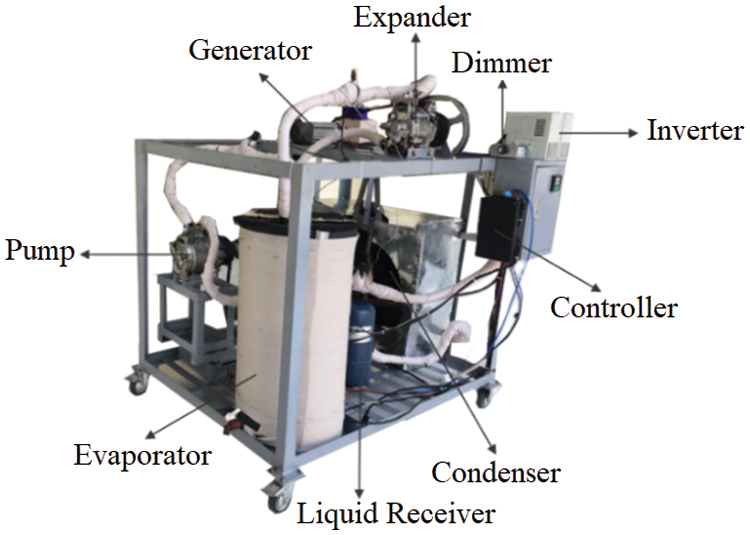
Figure 1: ORC developed
Scroll-expanders were selected because they are good for the low capacity of the ORC system [17]. The expander used in this research is a car AC compressor because of its suitability for low-cost ORC applications. It rotates the pulley and belt which is forwarded to a DC generator with a maximum power output of 750 Watt and produces electricity. In addition, this study used an air-cooling condenser, the type commonly used in room air conditioning systems.
The liquid receiver is installed on the ORC system as a supporting component while, the receiver refrigerant is installed between the condenser output and the pump input. The function of the receiver is to separate the working fluid phases in the form of liquid and gas before its fluid enters the pump. Furthermore, in the evaporator component and the piping system, an armaplex sponge is installed as an insulator to create a closed system and avoid heat loss to the environment.
The heat is installed on the evaporator tube as a heat source and its used oil as a distributor. A thermostat is installed in the heater circuit to adjust temperature which enables it to be controlled. The piping system of the ORC is made of copper alloy C12200 ASTM B280 standard measuring 1.905 × 10⁻² m with a thickness of 8 × 10⁻⁴ m. Each side of the pipe is insulated with an armaplex sponge to avoid heat loss.
The parameters measured on the ORC system are the temperature and pressure of the working fluid at each outlet of the pump, evaporator, expander and condenser. Fluid flow rate is measured before entering the inlet line of the pump, in addition to the evaporator temperature and the power generated from the generator. Fig. 2 shows the work scheme used in this research.
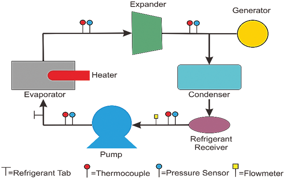
Figure 2: ORC system work scheme
Pressure and temperature sensors are installed at each outlet of the pump, evaporator, expander and condenser. The fluid flow rate is measured using a flowmeter sensor while, pump and generator rotation are measured using a tachometer. In addition, generator power is measured using a voltmeter and an ampere meter and the results were analyzed using Engineering Equation Solver (EES) software. According to the test, data on changes in mass flow rate, enthalpy, power and energy efficiency are obtained at each variation of motor frequency in R-134a fluid.
The test was carried out at various motor frequencies of 7.5, 10, 12.5, 15, 17.5 and 20 Hz, with the evaporator and condenser temperatures setting at 373.15 and 293.15 K, respectively at an initial pressure of 5 × 10⁵ Pa. This experiment uses R-134a refrigerant as a working fluid which has physical properties as shown in Tab. 1.
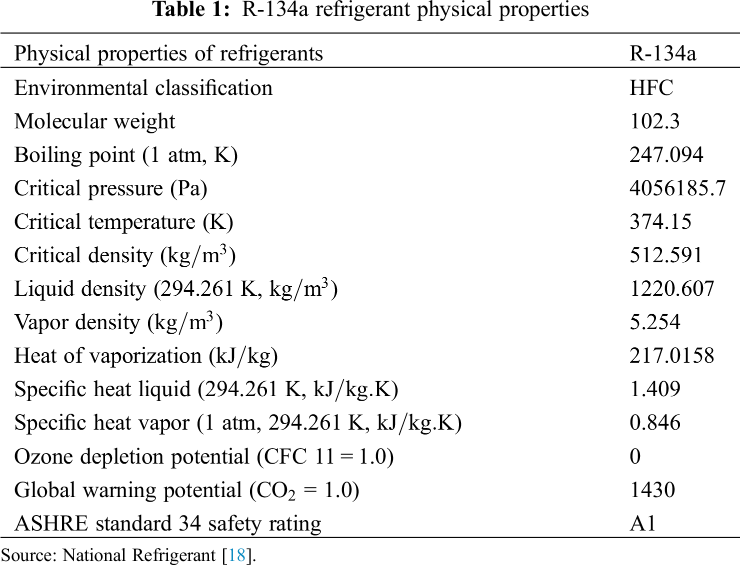
In this research, the R-134a refrigerant includes car air conditioning systems, water coolers, including domestic and intermediate commercial refrigeration systems. It is the main chemical component that stabilizes heat movement in the system therefore, making it non-flammable, odorless, non-corrosive and non-toxix, making the environment friendlier [19]. Furthermore, it is used because of its thermodynamic performance, safety, and material availability. Therefore, it is suitable for ORC applications.
Four main components are analyzed in the ORC system, they include: pump, evaporator, expander, condenser. In this research, the system efficacy was determined in a predetermined thermodynamic equation. Meanwhile the potential and kinetic energy generated from the fluid vapor on the work and heat transfer were neglected. The environmental effect is neglected because the piping system has been designed to use an insulator hence the ambient temperature which has no effect on the ORC cycle.
The energy equation in the system with constant flow per unit mass is formulated as follows:
In this case, pump and expander are assumed to be in an isentropic state, where there is no change in temperature/entropy while, the evaporator and condenser are not affected by work. Therefore, the energy conservation relationship for each of these components is expressed as:
Working Fluid Mass Flow Rate (kg/s)
The mass flow rate is calculated on the component after the condenser with the following formula [20]:
Pump Work and Power (Watt) (q = 0)
The pump power is determined by calculating the mass flow rate and the enthalpy difference at the pump input and output.
Heat Input of the Evaporator
The heat input of the evaporator is determined by calculating the mass flow rate and the enthalpy difference at the input and output of the evaporator [21,22].
Heat Output of the Condenser
The heat output of the condenser is determined by calculating the mass flow rate and the enthalpy difference at the input and output of the condenser [21].
Expander Work and Power Output
The expander power is determined by calculating the mass flow rate and the enthalpy difference at the input and output of the expander.
Energy Efficiency
The energy efficiency of the ORC system is determined by calculating the difference between the power at the pump and at the expander. The difference in pump and expander power is a reference for determining energy efficiency in the ORC system [20].
where,
3.1 Results of the ORC Component Measurement Parameters
Data were collected from three experiments and the average results were obtained. Cycle testing was carried out after running for 15 min, where system was stable as described in Tab. 2.
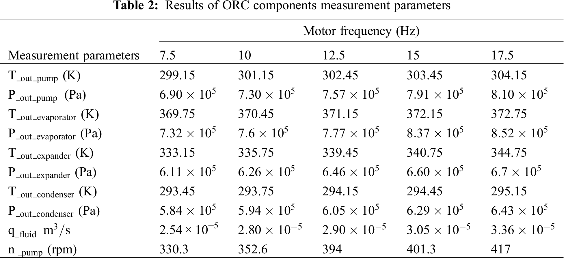
The mass flow rate was determined from the fluid flow rate and density when it enters the pump inlet while, pressure and temperature from the sensor at that point were analyzed using EES. In addition, the available data was entered into the EES to determine the fluid phase and density. Tab. 3 shows the mass flow rate of the R-134a working fluid.
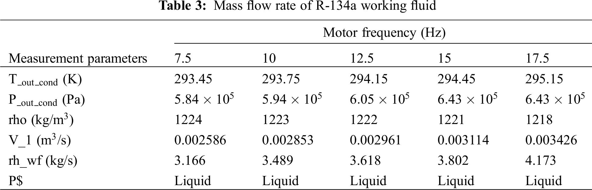
The value of mass flow rate was determined from the fluid flow rate and density. Density changes are affected by increased temperature and pressure due to increased pump rotation. Meanwhile, the mass flow rate continued to show an increase along with the increase in the frequency of the pump motor. Furthermore, increasing the pump motor frequency produced an increase in pump speed. The results indicated that the lowest mass flow rate of 3.166 kg/s was obtained at the pump motor frequency of 7.5 Hz while, the highest mass flow rate value of 4.173 kg/s was obtained at the highest pump motor frequency of 17.5 Hz.
According to Quoilin et al., the size of the pump rotation also affects the flow rate of ORC working fluid [14]. The faster the rotation in a pump, the higher the mass flow rate in each fluid. This is because the faster the pump rotates, the fluid flow rate and pressure also increase therefore, affecting the mass flow rate of each fluid which also increases.
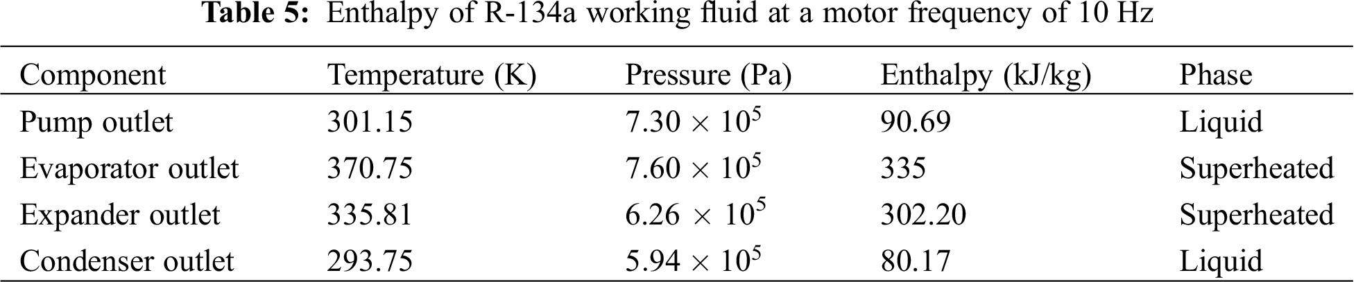
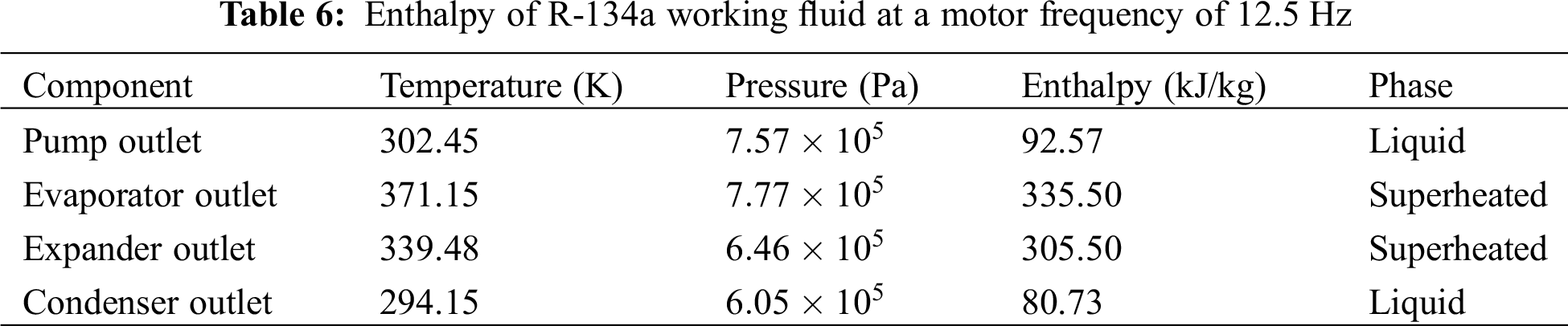
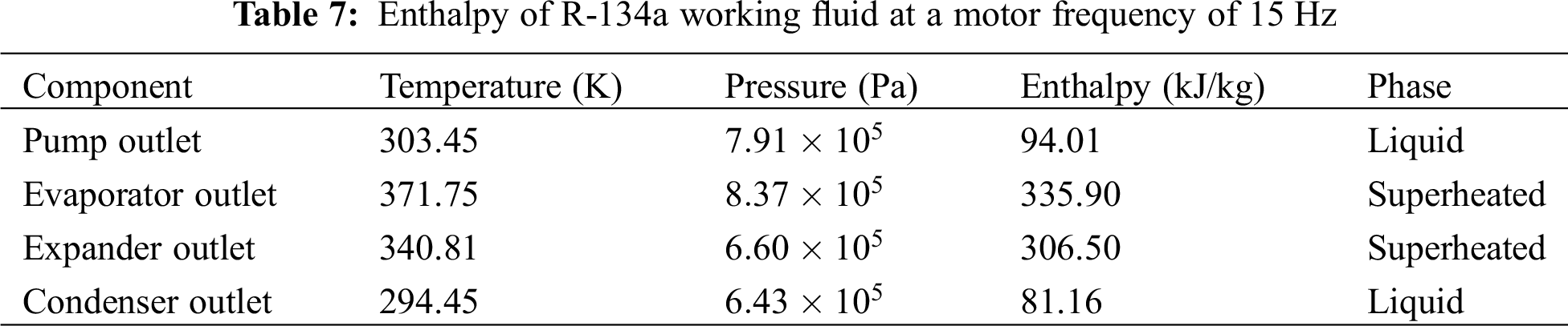
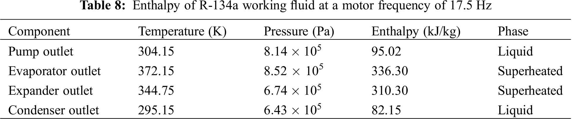
Each type of fluid has different thermodynamic characteristics, which affects the amount of enthalpy in working fluid. The enthalpy in the ORC system is determined from each main component output, which are pump, evaporator, expander and condenser output. The temperature and pressure data from the test were processed using EES. Tabs. 4–8 show the availability of enthalpy data.
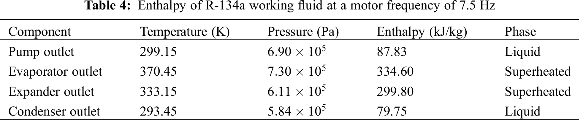
3.3.1 Motor Frequency of 7.5 Hz
3.3.2 Motor Frequency of 10 Hz
3.3.3 Motor Frequency of 12.5 Hz
3.3.4 Motor Frequency of 15 Hz
3.3.5 Motor Frequency of 17.5 Hz
Fig. 3 shows that the ORC system has the highest average enthalpy value at the motor frequency of 17.5 Hz (the highest pump rotation speed). The highest temperature and pressure are obtained in this motor while, the lowest average enthalpy value is at the motor frequency of 7.5 Hz (the lowest pump rotation speed) and produces the lowest temperature and pressure. Phase changes occur in the working fluid in the condenser, from the superheated phase to the liquid phase. Furthermore, in the evaporator, it changes from the liquid phase to the superheated.
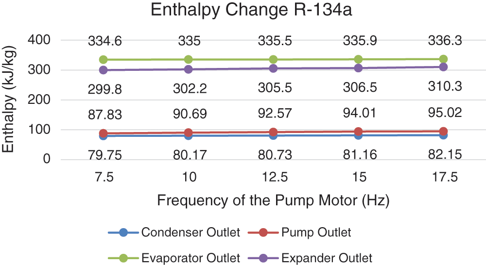
Figure 3: Enthalpy change R-134a
3.4 Energy Efficiency Comparison
Energy efficiency using the R-134a working fluid decreases with increasing pump rotation, i.e., the pump rotation is directly proportional to the pump power. If the increase in pump power is not proportional to the increase in expander power, it will cause a decrease in energy efficiency. This result is in accordance with that of Xi et al. which shows a decrease in isentropic efficiency with increasing pump rotation [23].
In testing the ORC system, the highest and lowest efficiencies are at the pump motor frequencies of 7.5 and 17.5 Hz, respectively. A pump motor frequency of 7.5 Hz records an efficiency of 10.82% and a motor frequency of 17.5 Hz records an efficiency of 5.43%.
Power output is the amount of power generated by the generator. A DC generator with a maximum power of 750 Watt is installed in the ORC system with a source of rotation from the expander rotation. The expander rotation is forwarded to the generator using a pulley and belt. The faster the generator rotates, the more power is generated.
Generator power is measured by the multiplication product of the voltage and ampere generated by the generator using a voltmeter and an ampere meter. Tab. 9 shows the generator output power of the R-134a working fluid at each motor frequency. In addition, pump rotation and generator rotation are measured using a tachometer to compare the rotation speed of the pump and generator when using the R-134a working fluid.
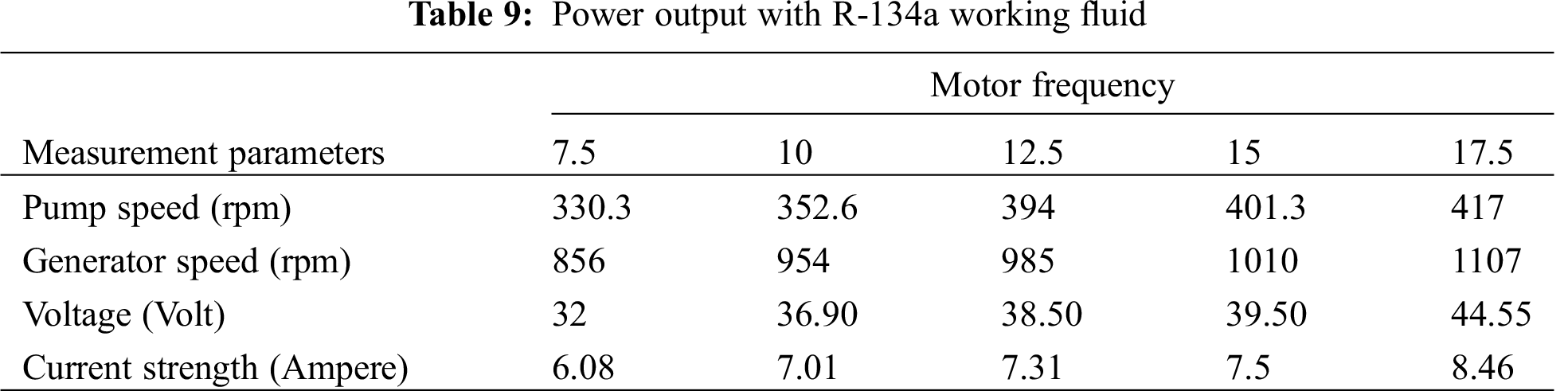
Fig. 5 shows an increase in power output occurs at each increase in pump rotation speed i.e., when the pump rotates faster, the fluid flow rate also increases. An increase in fluid flow rate causes the expander rotation to speed up due to an increase in pump rotation speed. Meanwhile, an increase in the expander speed causes the generator rotation to increase because the source of the generator rotation is the expander rotation. Furthermore, an increase in generator speed causes the resulting power output to increase as well. According to Imran et al., the generator power output increases with increasing pump speed [24]. The lowest power output with R-134a working fluid occurs at a pump motor frequency of 7.5 Hz which is the lowest frequency at 194.67 Watt. Meanwhile, the highest generator power output is at the highest pump motor speed of 17.5 Hz at 377.31 Watt.
Increasing the pump rotational speed increases the power output however, the results are still less profitable. From Fig. 4, it was observed that an increase in motor frequency actually affects a decrease in system efficiency. Therefore, an increase in pump rotational speed as an increase in capital energy is not proportional to the increase in energy gained. This indicates that the energy capital needed to drive the pump is not completely converted by the system. Therefore, a decrease in efficiency occurs due to an increase in mechanical friction losses, fluid flow friction losses, fluid leaks and other losses that are undetectable.
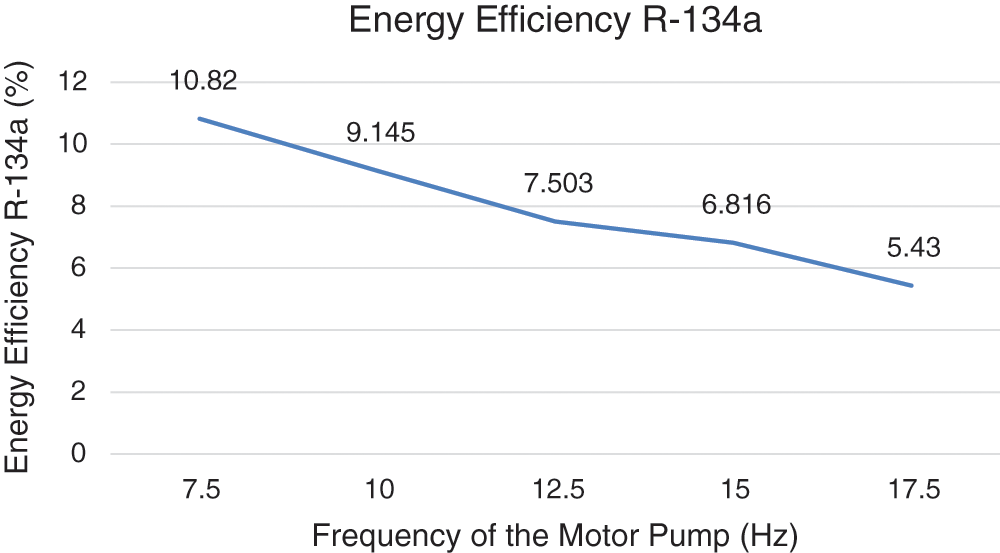
Figure 4: Energy efficiency R-134a
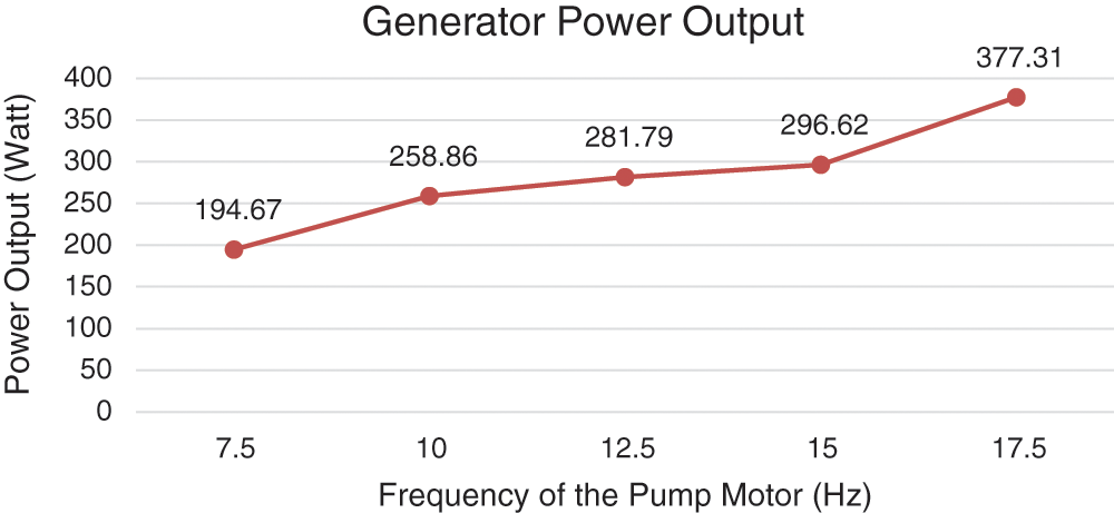
Figure 5: Generator power output
Based on this research, it was discovered that the ORC system processes low heat sources such as in low temperature geothermal fluid into electrical energy by using organic fluids. One of the main and most important components of the system is the pump which has a rotation effect on the system performance i.e., mass flow rate, enthalpy and generator power output are directly proportional to pump rotation.
The results showed that the maximum generator output power of 377.31 Watt occurred at the highest pump rotation speed of 17.5 Hz. Meanwhile, the lowest generator output power of 194.67 Watt occurred at the pump motor frequency of 7.5 Hz. In contrast to generator power output, energy efficiency is indirectly proportional to the pump speed. Therefore, indicating that the highest and lowest energy efficiency of 10.82% and 5.43% occurred at pump motor frequencies of 7.5 and 17.5 Hz, respectively.
Funding Statement: The authors express gratitude to LPPM UNS, for funding this research project titled “Increasing the Capacity of Geothermal Power Plants Using Exergy Analysis to Support Government Policy in the Development of a 35 Thousand MW Power Plant (Hibah Penelitian Unggulan UNS (PU-UNS))”.
Conflicts of Interest: The authors declare that they have no conflicts of interest to report regarding the present study.
1. Jalili, M., Chitsaz, A., Hashemian, M., Rosen, M. A. (2020). Economic and environmental assessment using emergy of a geothermal power plant. Energy Conversion and Management, 228, 113666. DOI 10.1016/j.enconman.113666. [Google Scholar] [CrossRef]
2. Muhammad, U., Imran, M., Lee, D. H., Park, B. S. (2015). Design and experimental investigation of a 1 kW organic Rankine cycle system using R245fa as working fluid for low-grade waste heat recovery from steam. Energy Conversion and Management, 103, 1089–1100. DOI 10.1016/j.enconman.2015.07.045. [Google Scholar] [CrossRef]
3. Jouhara, H., Khordehgah, N., Almahmoud, S., Delpech, B., Chauhan, A. et al. (2018). Waste heat recovery technologies and applications. Thermal Science and Engineering Progress, 6, 268–289. DOI 10.1016/j.tsep.2018.04.017. [Google Scholar] [CrossRef]
4. Yadav, K., Sircar, A. (2019). Selection of working fluid for low enthalpy heat source Organic Rankine Cycle in Dholera, Gujarat, India. Case Studies in Thermal Engineering, 16, 100553. DOI 10.1016/j.csite.2019.100553. [Google Scholar] [CrossRef]
5. Kazemi, S., Nor, M. I. M., Teoh, W. H. (2020). Thermodynamic and economic investigation of an ionic liquid as a new proposed geothermal fluid in different organic rankine cycles for energy production. Energy, 193, 116722. DOI 10.1016/j.energy.2019.116722. [Google Scholar] [CrossRef]
6. Yağlı, H., Koç, Y., Kalay, H. (2021). Optimisation and exergy analysis of an Organic Rankine Cycle (ORC) used as a bottoming cycle in a cogeneration system producing steam and power. Sustainable Energy Technologies and Assessments, 44, 100985. DOI 10.1016/j.seta.2020.100985. [Google Scholar] [CrossRef]
7. Köse, Ö., Koç, Y., Yağlı, H. (2021). Energy, exergy, economy and environmental (4E) analysis and optimization of single, dual and triple configurations of the power systems: Rankine cycle/Kalina cycle, driven by a gas turbine. Energy Conversion and Management, 227, 113604. DOI 10.1016/j.enconman.2020.113604. [Google Scholar] [CrossRef]
8. Altun, A. F., Kilic, M. (2020). Thermodynamic performance evaluation of a geothermal ORC power plant. Renewable Energy, 148, 261–274. DOI 10.1016/j.renene.2019.12.034. [Google Scholar] [CrossRef]
9. Jafary, S., Khalilarya, S., Shawabkeh, A., Wae-hayee, M., Hashemian, M. (2021). A complete energetic and exergetic analysis of a solar powered trigeneration system with two novel Organic Rankine Cycle (ORC) configurations. Journal of Cleaner Production, 281, 124552. DOI 10.1016/j.jclepro.2020.124552. [Google Scholar] [CrossRef]
10. Encabo Cáceres, I., Agromayor, R., Nord, L. O. (2017). Thermodynamic optimization of an organic rankine cycle for power generation from a Low temperature geothermal heat source. Proceedings of the 58th Conference on Simulation and Modelling (SIMS 58) Reykjavik, vol. 138, pp. 251–262. Iceland, DOI 10.3384/ecp17138251. [Google Scholar] [CrossRef]
11. Clemente, S., Micheli, D., Reini, M., Taccani, R. (2012). Energy efficiency analysis of organic rankine cycles with scroll expanders for cogenerative applications. Applied Energy, 97, 792–801. DOI 10.1016/j.apenergy.2012.01.029. [Google Scholar] [CrossRef]
12. Bianchi, G., Fatigati, F., Murgia, S., Cipollone, R. (2017). Design and analysis of a sliding vane pump for waste heat to power conversion systems using organic fluids. Applied Thermal Engineering, 124, 1038–1048. DOI 10.1016/j.applthermaleng.2017.06.083. [Google Scholar] [CrossRef]
13. Zeleny, Z., Vodicka, V., Novotny, V., Mascuch, J. (2017). Gear pump for low power output ORC–An efficiency analysis. Energy Procedia, 129, 1002–1009. DOI 10.1016/j.egypro.2017.09.227. [Google Scholar] [CrossRef]
14. Quoilin, S., van, D. B. M., Declaye, S., Dewallef, P., Lemort, V. (2013). Techno-economic survey of Organic Rankine Cycle (ORC) systems. Renewable and Sustainable Energy Reviews, 22, 168–186. DOI 10.1016/j.rser.2013.01.028. [Google Scholar] [CrossRef]
15. Qiang F. Y. Hung, T. C., He, Y. L., Wang, Q., Wang, S. et al. (2017). Operation characteristic and performance comparison of Organic Rankine Cycle (ORC) for low-grade waste heat using r245fa, r123 and their mixtures. Energy Conversion and Management, 144, 153–163. DOI 10.1016/j.enconman.2017.04.048. [Google Scholar] [CrossRef]
16. Xu, W., Deng, S., Zhang, Y., Zhao, D., Zhao, L. (2019). How to give a full play to the advantages of zeotropic working fluids in Organic Rankine Cycle (ORC). Energy Procedia, 158, 1591–1597. DOI 10.1016/j.egypro.2019.01.374. [Google Scholar] [CrossRef]
17. Campana, C., Cioccolanti, L., Renzi, M., Caresana, F. (2019). Experimental analysis of a small-scale scroll expander for low-temperature waste heat recovery in Organic Rankine Cycle. Energy, 187, 115929. DOI 10.1016/j.energy.2019.115929. [Google Scholar] [CrossRef]
18. Refrigerant, N. (2016). Refrigerant reference guide, pp. 49. National Refrigeration Inc., 149. DOI 10.1186/s12931-016-0346-3. [Google Scholar] [CrossRef]
19. Bell, I. H., Domanski, P. A., McLinden, M. O., Linteris, G. T. (2019). The hunt for nonflammable refrigerant blends to replace R-134a. International Journal of Refrigeration, 104, 484–495. DOI 10.1016/j.ijrefrig.2019.05.035. [Google Scholar] [CrossRef]
20. Çengel, Y. A., Cimbala, J. M. (2014). Fluid mechanics: Fundamentals and applications, 3rd ed New York: McGraw-Hill. [Google Scholar]
21. Çengel, Y. A. (2002). Heat transfer a practical approach. New York: McGraw-Hill. [Google Scholar]
22. Boles, M. A., Çengel, Y. A. (2019). Thermodynamics an engineering approch. New York: McGraw-Hill Education. [Google Scholar]
23. Xi, H., Li, M. J., Zhang, H. H., He, Y. L. (2019). Experimental studies of organic rankine cycle systems using scroll expanders with different suction volumes. Journal of Cleaner Production, 218, 241–249. DOI 10.1016/j.jclepro.2019.01.302. [Google Scholar] [CrossRef]
24. Imran, M., Park, B. S., Kim, H. J., Lee, D. H., Usman, M. (2015). Economic assessment of greenhouse gas reduction through low-grade waste heat recovery using Organic Rankine Cycle (ORC). Journal of Mechanical Science and Technology, 29(2), 835–843. DOI 10.1007/s12206-015-0147-5. [Google Scholar] [CrossRef]
 | This work is licensed under a Creative Commons Attribution 4.0 International License, which permits unrestricted use, distribution, and reproduction in any medium, provided the original work is properly cited. |