| Energy Engineering |
DOI: 10.32604/EE.2021.015011
ARTICLE
The Multi-Objective Optimization of AFPM Generators with Double-Sided Internal Stator Structures for Vertical Axis Wind Turbines
1Jiangsu Jinfeng Technology Co., Ltd., Yancheng, 224100, China
2School of Automation, Nanjing University of Science and Technology, Nanjing, 210094, China
3School of Electrical Engineering and Automation, Henan Polytechnic University, Jiaozuo, 454000, China
*Corresponding Author: Dandan Song. Email: songdandangoldwind@163.com
Received: 15 October 2020; Accepted: 18 December 2020
Abstract: The axial flux permanent magnet (AFPM) generator with double-sided internal stator structure is highly suitable for vertical axis wind turbines due to its high power density. The performance of the AFPM generator with double-sided internal stator structure can be improved by the reasonable design of electromagnetic parameters. To further improve the overall performance of the AFPM generator with double-sided internal stator structure, multivariable (coil width ωc, permanent magnet thickness h, pole arc coefficient αp and working air gap lg) and multi-objective (generator efficiency η, total harmonic distortion of the voltage THD and induced electromotive force amplitude EMF) functional relationships are innovatively established. Orthogonal analysis, mean analysis and variance analysis are performed on the influence parameters by combining the Taguchi method and response surface methodology to study the influence degrees of each influence parameter on the optimization objectives to determine the most appropriate electromagnetic parameters. The optimization results are verified by 3D finite element analysis. The optimized APFM generator with double-sided internal stator structure exhibits superior economy, stronger magnetic density, higher efficiency and improved power quality.
Keywords: Wind turbine; double-sided internal stator structure; multi-objective optimization; axial flux permanent magnet generator
Axial flux permanent magnet (AFPM) generators, with their compact construction, high efficiency and high power density [1–3], have gained increasing interests from many researchers. AFPM generators are classified into four types of structures [4–6]. Among them, the coreless stator AFPM generator with double-sided internal stator structure, also known as TORUS [6], is the most suitable for small vertical axis wind turbines [7] because of its high stability which is attributed to the no cogging torque [8,9]. Wind energy can be better utilized through the reasonable electromagnetic parameter designs of AFPM generators with TORUS [10–12].
Efficiency, total harmonic distortion (THD), induced electromotive force amplitude (EMF) and other indicators are usually considered as the optimized objectives in AFPM generators with TORUS [13–17]. To optimize an AFPM generator, winding structures [18–20], permanent magnet magnetic poles [21], magnet thickness, shapes [22–24] and magnetization directions [25] are taken as singular influencing factors to study the efficiency, THD, electromagnetic torque and no-load back EMF of the AFPM generator. However, generator optimization is a typical multi-objective equation for multiple influencing factors rather than a single influencing factor.
Many scholars have realized the limitations of a single influencing factor when optimizing an AFPM generator. Multiple influencing factors, including windings, air gaps, temperatures and permanent magnets [26–30], are considered when improving the performance of the AFPM generator. However, the optimization objectives have not been fully considered.
In this paper, in addition to the EMF and THD of an AFPM generator with TORUS, efficiency is also added as an optimization objective. The influencing factors of coil width ωc, permanent magnet thickness h, pole arc coefficient αp and working air gap lg on the three optimization objectives are studied and have not been considered in previous research. The combination of the Taguchi method and response surface methodology is widely used to solve multivariable and multi-objective problems due to its high efficiency [31,32]. This research is based on a 300 W prototype platform [33] for performance optimization of an AFPM generator with TORUS. Orthogonal analysis, mean analysis and variance analysis are performed on the influence parameters by the Taguchi method to study the influence degrees of each influence parameter on the optimization objectives to determine the weak electromagnetic parameters, while the electromagnetic parameters with strong influence are determined by response surface method. The optimization results can be verified by 3D finite element analysis (FEA). According to the optimization results, the cost of the AFPM generator with TORUS is reduced by 6.4%, the air gap flux density is increased by 1%, the efficiency is increased by 0.3% and the THD is reduced by 1.3%.
2 Brief Introduction of Generator Design and Platform
The AFPM generator with TORUS rotates under the mechanical energy of the driving motor. The stator coil current is induced by the rotating magnetic field generated by the rotors. The average induced electromotive force of a single conductor [13] is shown in Formula (1).
where Ω is the mechanical angular velocity of the generator, Bδav is the average air gap magnetic density, and p is the magnetic pole pair. D0 is the outer diameter of the permanent magnet, and Di is the inner diameter of the permanent magnet.
The induction electromotive force of a single phase winding [13] is shown in formula (2).
where a is the number of parallel branches of each phase armature winding at the stator side, N1 is the number of turns of each coil, kw is the coefficient of the stator winding, αi is the calculated pole arc coefficient and Bδ is the air gap pole magnetic density.
According to the design principle of the generator, if the winding phase number of the generator is m, the current is Ia, the rated speed is n and the generator input power Pe [13] can be shown in formula (3).
Generator efficiency is an important parameter used to measure generator performance. The main loss of the AFPM generator with TORUS is copper loss Pcu, and its efficiency can be expressed by formula (4).
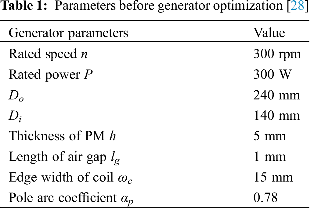
According to the actual working situation, the parameters of the AFPM generator with TORUS before optimization are shown in Tab. 1.
The research of multivariable and multi-objective optimization in this paper is based on the prototype of a 300 W generator. The AFPM generator with TORUS and the experimental platform are shown in Fig. 1. The stator adopts fractional slot concentrated winding, which is fixed by epoxy resin. Surface-mounted permanent magnets with pole pairs of 10 are used on both sides of the rotor. The driving motor can simulate the effect of a wind wheel and drive the generator to run through mechanical energy. The electric energy generated by the generator drives the small load to work through rectification and inversion.
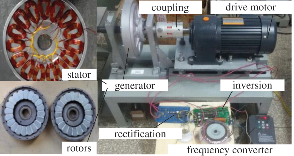
Figure 1: Diagram of generator structure and experimental platform
3 Multi-Objective Optimization
Taguchi method is a combination of determining variable factors, which is very suitable for the analysis of the influence degree of each parameter, while the response surface method is a more accurate parameter selection based on the three-dimensional surface formed by the influence of different intervals. Therefore, the electromagnetic parameters with weak influence are determined by Taguchi method, while the parameters with strong influence are determined by response surface methodology. The combination of Taguchi method and response surface method can improve the performance of the AFPM generator with TORUS.
3.1 Orthogonal Experiments of Taguchi Method
Several groups of reliable experiments are selected by the Taguchi method to replace large numbers of experiments [34], which greatly reduces the cost of experiments. The method is easy to understand and can efficiently obtain the best design value. Taguchi method has been widely used in production workshops and academia [35,36]. In this paper, Taguchi method is used flexibly, and the main flow chart of Taguchi method is shown in Fig. 2.
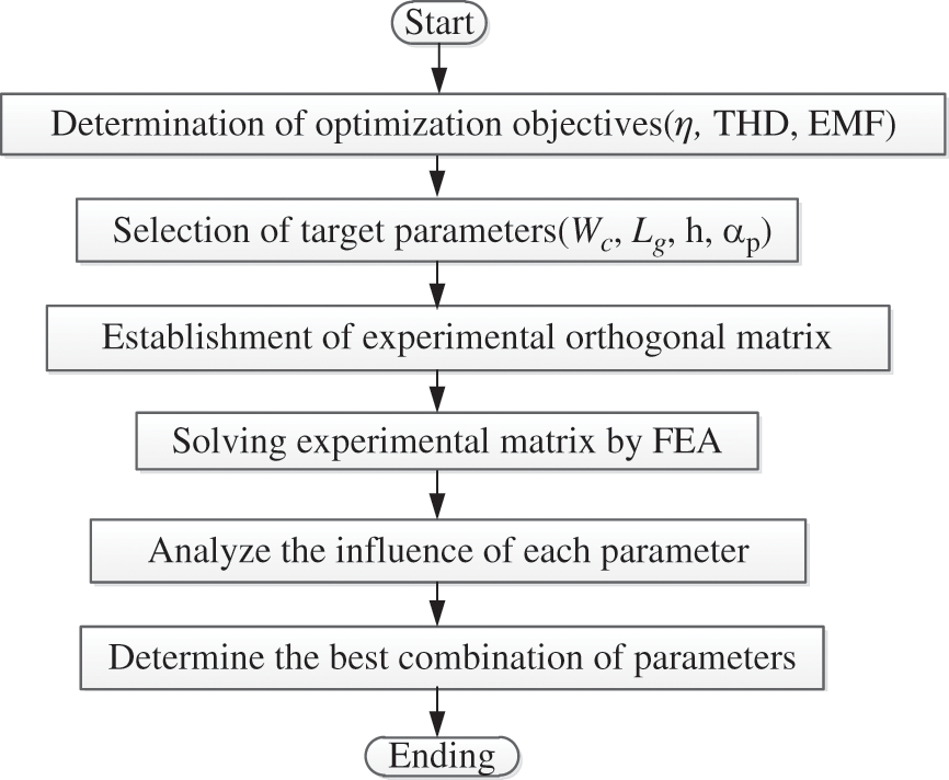
Figure 2: Flow chart of Taguchi method
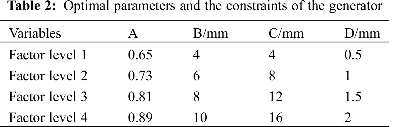
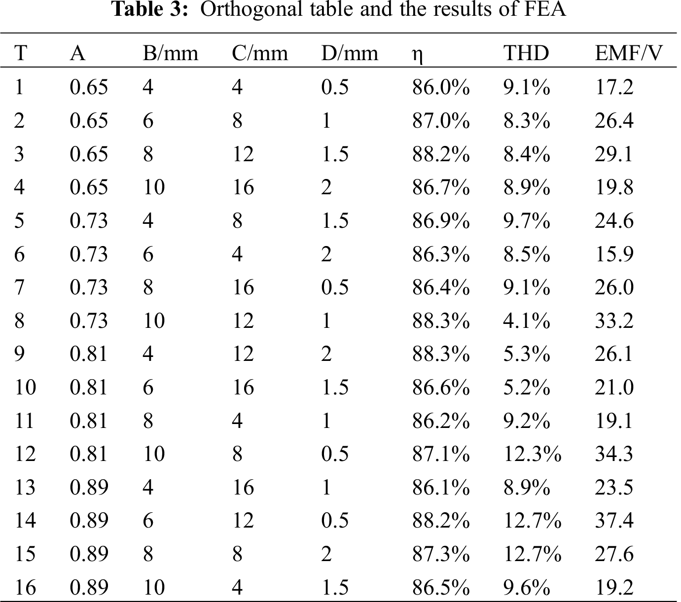
The multivariable and multi-objective equations are established with the pole arc coefficient αp(A), permanent magnet thickness h(B), coil width ωc(C) and working air gap lg(D) as influencing factors, and η, THD and EMF as optimization objectives. In the orthogonal experiment, the objective of optimization is called the quality characteristic, the condition of influencing the quality characteristic is called the factor, and the value of the factor is called the factor level. The values of influencing factors under different factor levels are shown in Tab. 2. Traditional analytical variables need to be analyzed 44 = 256 times, while only 16 experimental matrices need to be analyzed by Taguchi method. The results of the orthogonal experiment by 3D FEA are shown in Tab. 3.
3.2 The Results and Analyses of Taguchi Method
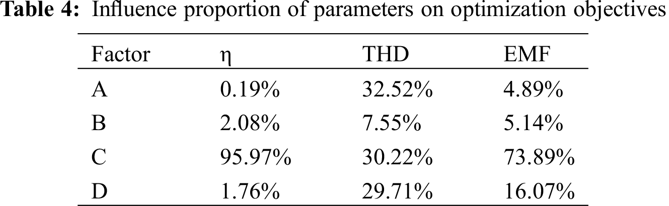
The influences of variable factors on the optimization objective vary with the level factors in Fig. 3. To study the influences of each parameter on the optimization objectives, variance analysis can be carried out on the results of 3D FEA in Tab. 2, which can be expressed by formula (5). The influence proportions of the parameters on the optimization objectives are shown in Tab. 4.
where FAi is the average value of the optimization objective under influence factor A and factor level i , and
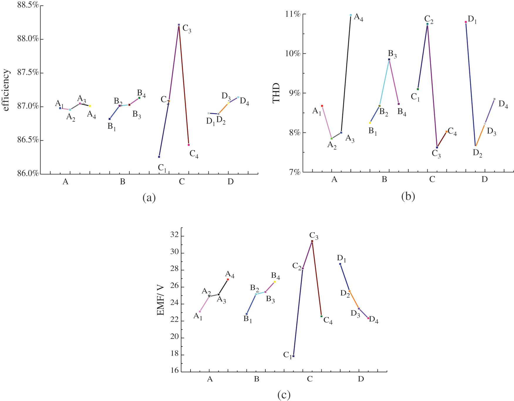
Figure 3: Analysis of generator performance under different influencing factors: (a) Analysis of efficiency under different influencing factors; (b) Analysis of THD under different influencing factors; (c) Analysis of EMF under different influencing factors
According to Fig. 3, the maximum combination of efficiency is A3B4C3D4, the minimum combination of THD is A2B1C3D2, and the maximum combination of EMF is A4B4C3D1. Based on the basic electromagnetic design, the weights of THD and efficiency η are higher than those of EMF. According to Tab. 4, factor A has the greatest impact on THD, and factor C has the greatest impact on efficiency η and EMF. The selection of important parameters A and C will be determined by the following response surface methodology.
Parameters B and D with weak influence can be determined by the Taguchi method. Because the influence of parameters B and D on the THD optimization objective is larger than the efficiency and EMF, the selection of parameters B and D will follow the principle of minimizing THD. Therefore, B1 and D2 are selected as the optimization parameters. The rated power of the AFPM generator with TORUS designed in this paper is 300 W. Therefore, the optimized generators will be checked again to meet the rated power index of 300 W. However, when parameter B is selected as 4 mm, the generator cannot meet the rated power index of 300 W. The power of generator can be improved by increasing the thickness of permanent magnet. However, according to Fig. 3b, THD will be increased when parameter B is selected as 6 mm. Therefore, the selection of parameter B maintains the original size of 5 mm.
3.3 Response Surface Methodology
The response surface methodology simulates the mathematical models between the optimization objectives and the influencing factors through the infinite approximation of the least square method to determine the electromagnetic parameters with strong influence. The changing trends of variable factors and optimization objectives are analyzed by graphical methods, and the optimal objectives under multivariate factors are obtained.
From the above optimization analysis, when A is between A2 and A4 and C is between C2 and C4, the optimal objective values can be achieved. Therefore, the ranges of influence factors can be expressed by Eqs. (6) and (7).
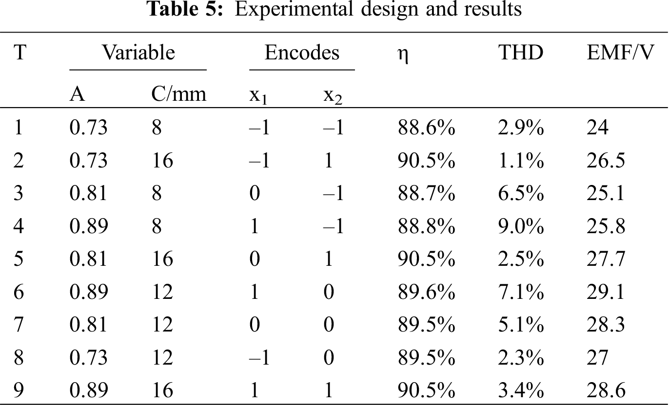
The different values of the pole arc coefficient A(αp) and coil side width C(ωc) are coded. To ensure that the predicted values of the whole experimental area have uniform accuracy, the central group design method is adopted. The experimental scheme and results are shown in Tab. 5.
3.4 The Results and Analyses of Response Surface Methodology
The results of 3D FEA can be obtained by 9 groups of orthogonal experiments with two influencing factors. The mathematical models of efficiency η, THD and EMF with respect to the polar arc coefficient (αp) and coil width (ωc) are as follows:
where x1 and x2 are the polar arc coefficient (αp) and the coil side width (ωc), y1, y2 and y3 are efficiency η, THD and EMF, respectively. The three-dimensional diagrams of the above mathematical models are shown in Figs. 4–6.
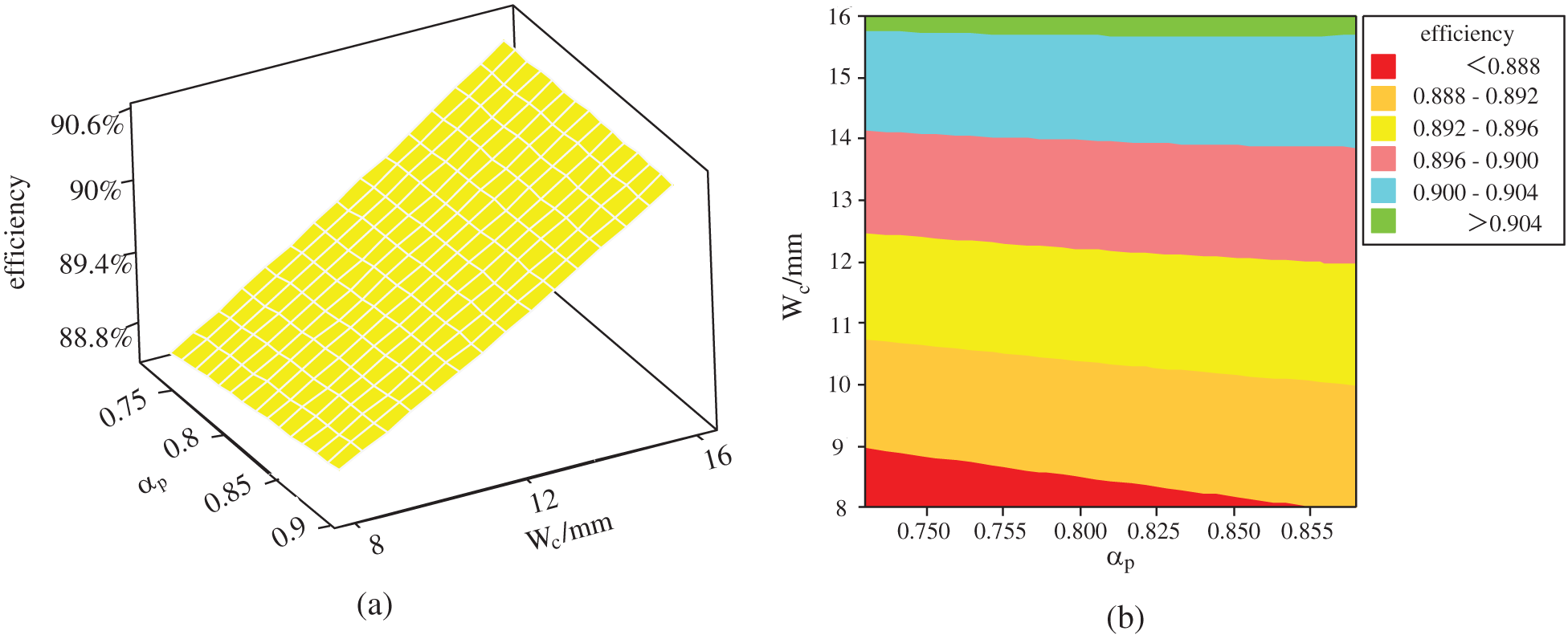
Figure 4: The influences of parameters ωc and αp on efficiency: (a) Surface graph of efficiency with respect to ωc and αp; (b) Contour map of efficiency with respect to ωc and αp
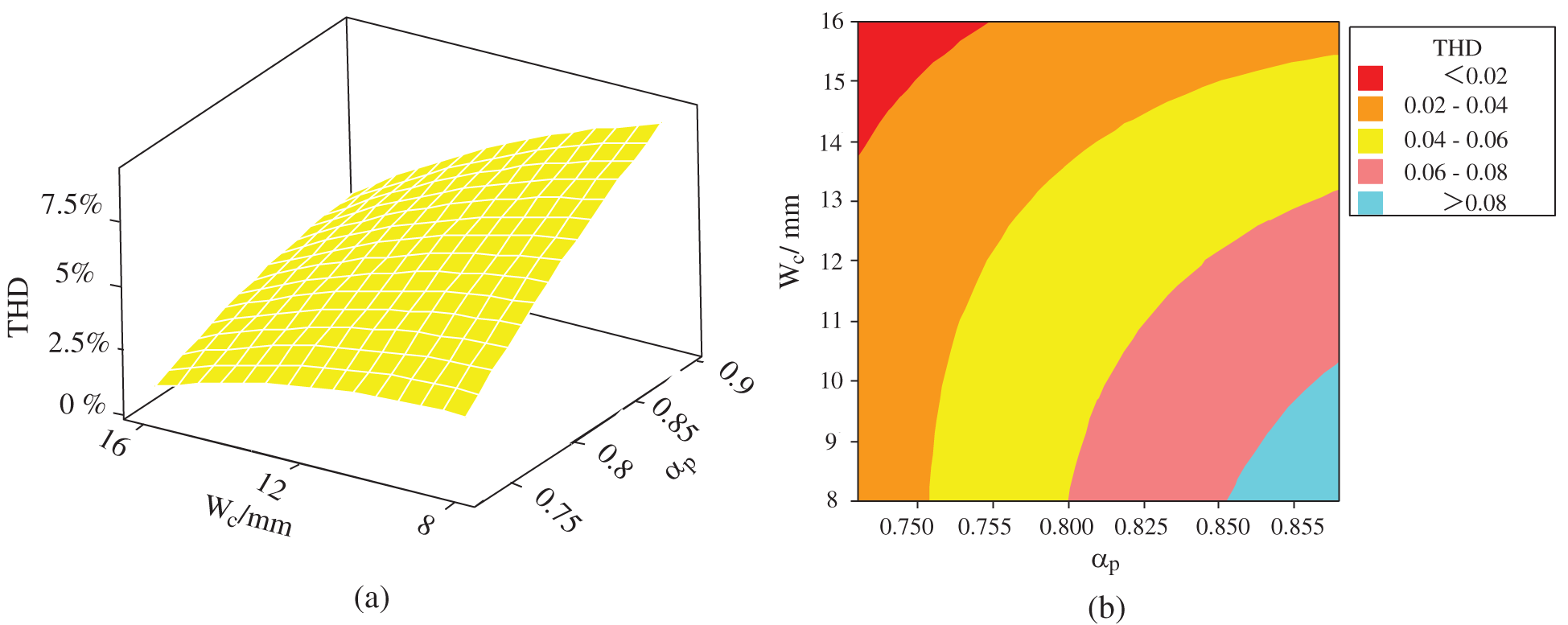
Figure 5: The influence of parameters ωc and αp on THD: (a) Surface graph of THD on ωc and αp; (b) Contour map of THD with respect to ωc and αp
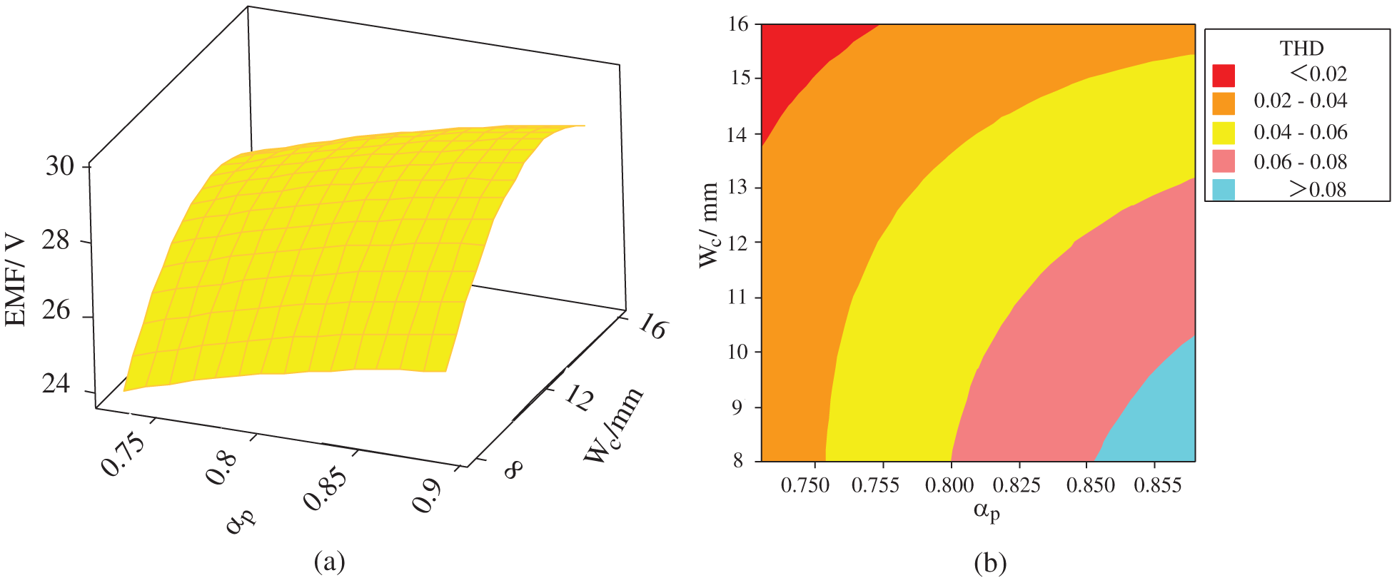
Figure 6: The influence of parameters ωc and αp on EMF: (a) Surface graph of EMF with respect to ωc and αp; (b) Contour map of EMF with respect to ωc and αp
Figs. 4a, 5a and 6a are the surface graphs of efficiency η, THD and EMF with respect to coil side width ωc and pole arc coefficient αp, respectively. The slope size of the surface reflects the significant influence of the interaction of two variables on the response target. The larger the slope is, the greater the influence of variable factors under interaction on the response target. For a more intuitive analysis, Figs. 4b, 5b and 6b show contour maps of efficiency η, THD and EMF with respect to coil side width ωc and pole arc coefficient αp. Different colors of contour maps represent different values of optimization targets. According to the analysis of Figs. 4–6, it can be seen that:
(1) In Fig. 4, when A(αp) is between 0.73 and 0.89 and C(ωc) is between 15.5 and 16 mm, the efficiency is greater than 90%.
(2) In Fig. 5, when A(αp) is between 0.73 and 0.76 and C(ωc) is between 14 and 16 mm, THD can reach the minimum value.
(3) In Fig. 6, when A(αp) is between 0.85 and 0.89 and C(ωc) is between 12 and 15 mm, the EMF can reach the maximum.
The final optimized results of response surface methodology are determined based on Minitab software, considering the weight of different optimization objectives affected by αp and ωc on the overall characteristics of the AFPM generator with TORUS. The relationship among generator efficiency η, THD and EMF on the overall optimal solution is shown in formula (11).
where A1, A2 and A3 are the weights of efficiency η, THD and EMF on the overall performance of the generator respectively, y is overall optimal solution of the generator performance.
Since the efficiency η and THD have greater weight on the overall performance of the generator , EMF of the generator only needs to meet the design value. Therefore, A1 is 40%, A2 is 40% and A3 is 20%. By analyzing the weight of different optimization objectives on the generator performance through formula (11) which is based on formulas (8)–(10), it can be concluded that the final optimization result of αp and ωc are 0.73 and 15.8 mm respectively.
4 Validation of Optimization Results
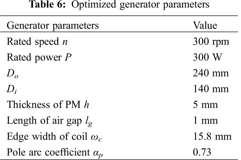
The optimized electromagnetic parameters of the generator are shown in Tab. 6. The performance of the optimized generator is verified by 3D FEA. The optimized generator performances are shown in Figs. 7–10.
The circumferential air gap flux density and radial air gap flux density under a pair of magnetic poles (360° electric angle) are studied to observe the change in geomagnetic density after optimization. The magnetic density in the middle of permanent magnets is the largest, and the magnetic density on both sides decreases with increasing air. Therefore, the magnetic density presents the shapes of sine waves and flat-topped waves in Figs. 7 and 8, respectively.
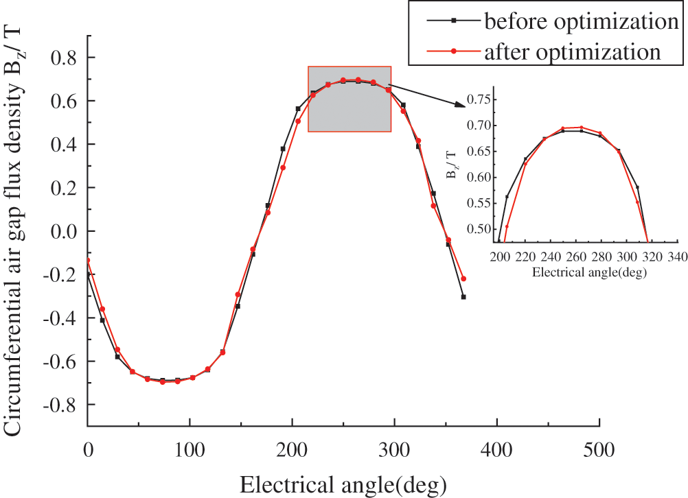
Figure 7: Circumferential air gap flux density
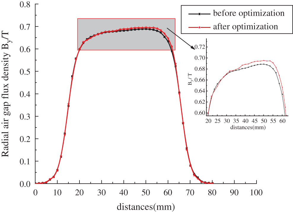
Figure 8: Radial air gap flux density
In Figs. 7 and 8, the circumferential air gap flux density amplitude of the optimized generator is changed from 0.690 T to 0.697 T, which is an increase of 1%, and the radial air gap flux density amplitude is changed from 0.688 T to 0.695 T, which is an increase of 1%.
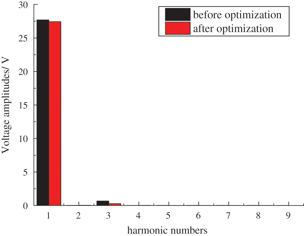
Figure 9: Harmonic content of generator
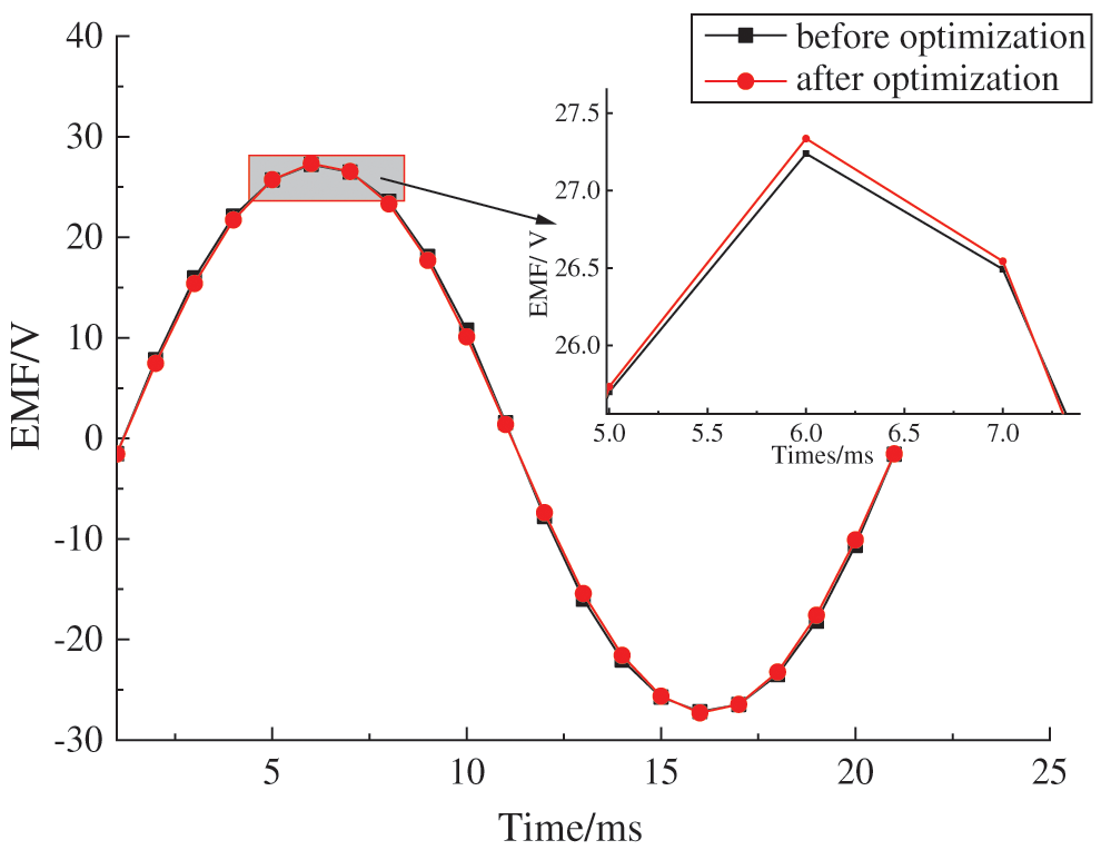
Figure 10: Generator phase voltage waveform in one cycle
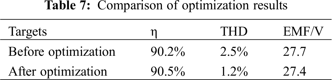
The harmonic analysis diagram of the optimized generator is shown in Fig. 9. As shown in Fig. 9, the third harmonic of the optimized AFPM generator with TORUS is obviously reduced, and THD is reduced from 2.5% to 1.2% with a decrease of 1.3%. The EMF of the optimized AFPM generator with TORUS is shown in Fig. 10. Fig. 10 shows that the amplitude of the fundamental wave is reduced from 27.7 V to 27.4 V, with a decrease of 1%; however, it meets the design requirements of the generator.
It can be seen from the modeling results that the efficiency η of the generator increases from 90.2% to 90.5%, which increases by 0.3%. The generator performances can be improved by the reasonable design of electromagnetic parameters. When the slot full ratio is kept constant, the generator efficiency η is improved by changing the coil side width; the permanent magnet consumption is reduced by 6.4% by changing the pole arc coefficient of the permanent magnet. The optimization results are shown in Tab. 7.
In this paper, the basic electromagnetic performances of the generator were studied, and the multi-objective optimization of the AFPM generator with TORUS was carried out through the combination of Taguchi method and response surface methodology based on the 300 W prototype platform.
The optimization results were verified by 3D FEA, which showed that the coil width ωc had the greatest influence on the AFPM generator with TORUS efficiency η and EMF, and the pole arc coefficient αp had the greatest impact on THD. After optimization of the AFPM generator with TORUS, the efficiency η was increased by 0.3%, THD was reduced by 1.3%, the permanent magnet was conserved by 6.4%, and the magnetic field density Bδ was increased by 1%.
In future research, in addition to the electromagnetic performance of the AFPM generator with TORUS, its physical performance, such as temperature rise and noise, will also be considered.
Funding Statement: This research is funded by Project Supported by Postdoctoral Science Foundation of Jiangsu Province, Grant No. 2019k237.
Conflicts of Interest: The authors declare that they have no conflicts of interest to report regarding the present study.
1. Gharehseyed, S., Vahedi, A., Nobahari, A., Darjazini, A. (2020). Torque characteristics enhancement of ring winding axial flux permanent magnet generator for direct-drive wind turbine. IET Electric Power Applications, 14(9), 1584–1591. DOI 10.1049/iet-epa.2020.0150. [Google Scholar] [CrossRef]
2. Park, Y., Jang, S., Choi, J., Choi, J., You, D. (2012). Characteristic analysis on axial flux permanent magnet synchronous generator considering wind turbine characteristics according to wind speed for small-scale power application. IEEE Transactions on Magnetics, 48(11), 2937–2940. DOI 10.1109/TMAG.2012.2204732. [Google Scholar] [CrossRef]
3. Arkadan, A. A., Hijazi, T. M., Masri, B. (2017). Design evaluation of conventional and toothless stator wind power axial-flux PM generator. IEEE Transactions on Magnetics, 53(6), 1–4. DOI 10.1109/TMAG.2018.2792846. [Google Scholar] [CrossRef]
4. Kahourzade, S., Mahmoudi, A. (2014). A comprehensive review of axial-flux permanent magnet machines. Canadian Journal of Electrical and Computer Engineering, 14(37), 19–33. DOI 10.1109/CJECE.2014.2309322. [Google Scholar] [CrossRef]
5. Capponi, F. G., Donato, G. D., Caricchi, F. (2012). Recent advances in axial-flux permanent-magnet machine technology. IEEE Transactions on Industry Applications, 48(6), 2190–2205. DOI 10.1109/TIA.2012.2226854. [Google Scholar] [CrossRef]
6. Huang, Y. K., Zhou, T. (2015). An overview on developments and researches of axial flux permanent magnet machines. Proceedings of the CSEE, 35(1), 192–205. [Google Scholar]
7. Zhu, J., Song, D. D. (2018). Comparative research on performance of iron and ironless axial flux wind generators. Journal of Astronautic Metrology and Measurement, 38(4), 79–85. [Google Scholar]
8. Caricchi, F., Capponi, F. G., Crescimbini, F., Solero, L. (2004). Experimental study on reducing cogging torque and no-load power loss in axial-flux permanent-magnet machines with slotted winding. IEEE Transactions on Industry Applications, 4(4), 1066–1075. [Google Scholar]
9. Zhang, Z. R., Geng, W. W. (2018). Overview of permanent magnet machines with ironless stator. Proceedings of the Chinese Society for Electrical Engineering, 38(2), 582–600+689. [Google Scholar]
10. Zamani, M. H., Riahy, G. H., Abedi, M. (2016). Rotor-speed stability improvement of dual stator-winding induction generator-based wind farms by control-windings voltage oriented control. IEEE Transactions on Power Electronics, 31(8), 5538–5546. DOI 10.1109/TPEL.2015.2495256. [Google Scholar] [CrossRef]
11. Bu, F., Hu, Y., Huang, W., Zhuang, S., Shi, K. (2015). Wide-speed-range-operation dual stator-winding induction generator DC generating system for wind power applications. IEEE Transactions on Power Electronics, 30(2), 561–573. DOI 10.1109/TPEL.2014.2308222. [Google Scholar] [CrossRef]
12. Zhu, L., Zhang, F., Jin, S., Ademi, S., Su, X. et al. (2019). Optimized power error comparison strategy for direct power control of the open-winding brushless doubly fed wind power generator. IEEE Transactions on Sustainable Energy, 10(4), 2005–2014. DOI 10.1109/TSTE.2018.2877439. [Google Scholar] [CrossRef]
13. Seo, S., Jang, G., Kim, J., Choi, J. (2018). Characteristic analysis and experimental verification for a double-sided permanent magnet linear synchronous generator according to magnetization array. IEEE Transactions on Applied Superconductivity, 28(3), 1–4. [Google Scholar]
14. He, C., Wu, T. (2019). Analysis and design of surface permanent magnet synchronous motor and generator. CES Transactions on Electrical Machines and Systems, 3(1), 94–100. DOI 10.30941/CESTEMS.2019.00013. [Google Scholar] [CrossRef]
15. Oh, J., Kwon, B. (2014). Improved transverse flux type permanent magnet reluctance generator with auxiliary rotor pole inserted permanent magnet. IEEE Transactions on Magnetics, 50(11), 1–4. [Google Scholar]
16. Hsieh, M., Hsu, Y., Dorrell, D. G., Chen, P. (2013). Evaluation of permanent magnet generator manufactured using postassembly magnetization. IEEE Transactions on Magnetics, 49(7), 4084–4087. DOI 10.1109/TMAG.2013.2248079. [Google Scholar] [CrossRef]
17. Liu, C., Yu, H., Hu, M., Liu, Q., Zhou, S. (2013). Detent force reduction in permanent magnet tubular linear generator for direct-driver wave energy conversion. IEEE Transactions on Magnetics, 49(5), 1913–1916. DOI 10.1109/TMAG.2013.2242873. [Google Scholar] [CrossRef]
18. Abdel-Khalik, A. S., Ahmed, S., Massoud, A. M. (2015). Low space harmonics cancelation in double-layer fractional slot winding using dual multiphase winding. IEEE Transactions on Magnetics, 51(5), 1–10. DOI 10.1109/TMAG.2014.2364988. [Google Scholar] [CrossRef]
19. Donato, G. D., Capponi, G. F., Rivellini, G. A., Caricchi, F. (2012). Integral-slot versus fractional-slot concentrated-winding axial-flux permanent-magnet machines: Comparative design, FEA, and experimental tests. IEEE Transactions on Industry Applications, 48(5), 1487–1495. DOI 10.1109/TIA.2012.2210011. [Google Scholar] [CrossRef]
20. Liu, Z. Y., Cai, J. (2018). 4-DOF hybrid-structure bearingless switched reluctance motor and its winding optimization design. Electric Machines and Control, 22(6), 49–61. [Google Scholar]
21. Hong, B. Q., Fan, X. B. (2018). The influence of asymmetric pole shoe on synchronous hydro generator. IEEJ Transactions on Electrical and Electronic Engineering, 13(11), 1654–1659. DOI 10.1002/tee.22728. [Google Scholar] [CrossRef]
22. Im, Y., Hwang, S., Jang, S., Choi, J. (2012). Analysis of torque pulsation considering interior permanent magnet rotor rib shape using response surface methodology. IEEE Transactions on Magnetics, 48(2), 979–982. DOI 10.1109/TMAG.2011.2176534. [Google Scholar] [CrossRef]
23. Chai, F., Liang, P., Pei, Y., Cheng, S. (2016). Magnet shape optimization of surface-mounted permanent magnet motors to reduce harmonic iron losses. IEEE Transactions on Magnetics, 52(7), 1–4. DOI 10.1109/TMAG.2016.2524010. [Google Scholar] [CrossRef]
24. Li, Y. B. (2015). Design and characteristic analysis of axial flux coreless permanent magnet synchronous generator (Master Thesis). Henan University of Technology, Jiaozuo. [Google Scholar]
25. Shi, C., Li, D., Qu, R., Zhang, H., Gao, Y. et al. (2017). A novel linear permanent magnet Vernier machine with consequent-pole permanent magnets and Halbach permanent magnet arrays. IEEE Transactions on Magnetics, 53(11), 1–4. DOI 10.1109/TMAG.2018.2792846. [Google Scholar] [CrossRef]
26. Gui, Y. C. (2018). Application of particle swarm optimization in optimization design of high density permanent magnet motor for vehicle (Master Thesis). Anqing Normal University, Anqing. [Google Scholar]
27. Guo, X., Zhang, B. Y. (2018). Multi objective optimization of low speed high torque direct drive PMSM based on hybrid particle swarm optimization. Journal of Mechanical & Electrical Engineering, 35(11), 1214–1219. [Google Scholar]
28. Zhu, J., Li, S. L., Song, D. D. (2018). Multi-objective optimisation design of air-cored axial flux PM generator. IET Electric Power Applications, 12(9), 1390–1395. DOI 10.1049/iet-epa.2018.5092. [Google Scholar] [CrossRef]
29. Hu, J. C., Fu, X. (2019). Multi-objective optimization of dual three-phase permanent magnet synchronous generator. Electric Machines & Control Application, 46(6), 77–83. [Google Scholar]
30. Xu, Y., Maki, N., Izumi, M. (2016). Optimization study of machine parameters for 10-MW salient-pole wind turbine HTS generators. IEEE Transactions on Applied Superconductivity, 26(3), 1–5. [Google Scholar]
31. Zhu, J., Song, D. D. (2018). Optimization of T-shaped suspension magnetic ring for vertical axis wind turbine. Applied Computational Electromagnetics Society Journal, 33(7), 781–789. [Google Scholar]
32. Li, S. L. (2018). Research on axial flux permanent magnet generator for direct drive vertical axis wind power generation (Master Thesis). Henan Polytechnic University, Jiaozhuo. [Google Scholar]
33. Zhu, J., Song, D. D. (2018). Multi objective optimization on suspension characteristics of vertical axis wind turbine. International Journal of Applied Electromagnetics and Mechanics, 58(2), 215–226. DOI 10.3233/JAE-180020. [Google Scholar] [CrossRef]
34. Zaman, M. A., Matin, M. A. (2015). Optimization of Jiles-Atherton hysteresis model parameters using Taguchi’s method. IEEE Transactions on Magnetics, 51(5), 1–4. DOI 10.1109/TMAG.2014.2357394. [Google Scholar] [CrossRef]
35. Lei, G., Liu, C., Li, Y., Chen, D., Guo, Y. et al. (2019). Robust design optimization of a high-temperature superconducting linear synchronous motor based on Taguchi method. IEEE Transactions on Applied Superconductivity, 29(2), 1–6. DOI 10.1109/TASC.2019.2898478. [Google Scholar] [CrossRef]
36. Lee, C., Shin, B. H., Bang, Y. (2016). Designing a permanent-magnetic actuator for vacuum circuit breakers using the Taguchi method and dynamic characteristic analysis. IEEE Transactions on Industrial Electronics, 63(3), 1655–1664. DOI 10.1109/TIE.2015.2494006. [Google Scholar] [CrossRef]
 | This work is licensed under a Creative Commons Attribution 4.0 International License, which permits unrestricted use, distribution, and reproduction in any medium, provided the original work is properly cited. |