 Open Access
ARTICLE
Intelligent PID Control Method for Quadrotor UAV with Serial Humanoid Intelligence
School of Mechanical Engineering, Hebei University of Science and Technology, Shijiazhuang, 050018, China
* Corresponding Author: Zhiying Qin. Email:
Computer Systems Science and Engineering 2024, 48(6), 1557-1579. https://doi.org/10.32604/csse.2024.054237
Received 22 May 2024; Accepted 12 August 2024; Issue published 22 November 2024
Abstract
Quadrotor unmanned aerial vehicles (UAVs) are widely used in inspection, agriculture, express delivery, and other fields owing to their low cost and high flexibility. However, the current UAV control system has shortcomings such as poor control accuracy and weak anti-interference ability to a certain extent. To address the control problem of a four-rotor UAV, we propose a method to enhance the controller’s accuracy by considering underactuated dynamics, nonlinearities, and external disturbances. A mathematical model is constructed based on the flight principles of the quadrotor UAV. We develop a control algorithm that combines humanoid intelligence with a cascade Proportional-Integral-Derivative (PID) approach. This algorithm incorporates the rate of change of the error into the inputs of the cascade PID controller, uses both the error and its rate of change as characteristic variables of the UAV’s control system, and employs a hyperbolic tangent function to improve the outer-loop control. The result is a double closed-loop intelligent PID (DCLIPID) control algorithm. Through MATLAB numerical simulation tests, it is found that the DCLIPID algorithm reduces the rise time by 0.5 s and the number of oscillations by 2 times compared to the string PID algorithm when a unit step signal is used as input. A UAV flight test was designed for comparison with the serial PID algorithm, and it was found that when the UAV planned the trajectory autonomously, the errors in the X-, Y-, and Z-directions were reduced by 0.22, 0.21, and 0.31 m, respectively. Under the interference environment of artificial wind about 3.6 m·s-1, the UAV hovering error in X-, Y-, and Z-directions are 0.24, 0.42, and 0.27 m, respectively. The simulation and experimental results show that the control method of humanoid intelligence and cascade PID can improve the real-time, control accuracy and anti-interference ability of the UAV, and the method has a certain reference value for the research in the field of UAV control.Keywords
Nomenclature
| UAV | Unmanned aerial vehicle |
| PID | Proportional integral differential |
| DCLIPID | The double closed loop humanoid intelligence PID |
| PWM | Pulse width modulation |
| MCU | Micro control units |
| LQ | Linear quadratic |
| LMI | Linear matrix inequality |
| VR | Virtual reality |
| ADRC | Adaptive disturbance rejection control |
| ANN | Artificial neural network |
| ESC | Electronic speed controller |
| TSMC | Two-stage matrix converter |
| HI | Humanoid intelligence |
| CNN | Convolutional neural network |
| OAM | Obstacle avoidance method |
Quadcopter UAVs have attracted considerable attention owing to their simple structure, compact body and flexible flight [1]. As the use of UAVs has become increasingly widespread, the requirements for machine performance have gradually increased, and the ability to maintain the desired flight performance is a basic requirement to meet the needs of different users. The advantages of quadcopter UAVs over hexacopter and octacopter UAVs are their small size and low cost, which are suitable for low-altitude flights, hovering, and can also be used in most scenarios [2]. Quadcopter UAVs play an indispensable role in various applications such as agricultural and plant spraying, power line inspection, aerial photography, 3D rendering, forest monitoring, fire rescue, air quality detection, and traffic management [3]. The successful implementation of these applications is closely related to the performance of flight controllers [4]. Many researchers have worked on developing high-performance flight-control strategies for quadrotors. For example, linear quadratic (LQ) controllers [5], model predictive controllers [6], adaptive block-controlled backstepping controllers [7], linear matrix inequality (LMI)-based controllers [8], robust cascade controllers [9], and neural-network-based controllers [10] have been developed. The UAV obtains an accurate attitude angle by fusing and solving the attitude information measured by sensors. The attitude angle is used in the flight control of the quadrotor, and the control system continuously adjusts the rotational speed of the motors to change the attitude of the airframe to achieve control. The core of the quadcopter design is attitude solving and flight control. At present, the control technology used by most UAV technology enterprises is still dominated by conventional (PID) control, owing to the influence of the commercialization nature [11]. This is mainly because the PID controller itself has high computational efficiency, is suitable for concurrent processing of onboard microcontrol units (MCUs), and has both robustness and stability in control, but requires high accuracy of the mathematical model. The accuracy of the mathematical model directly affects the effectiveness of the PID control algorithm, which cannot cope well with many real-time problems, in addition to communication delays, dynamic variations, and external interference [12]. Lopez-Sanchez et al. [13] surveyed applications of PID control structures in quadrotor UAVs paying attention to linear, nonlinear, discontinuous, fractional order, intelligent and adaptive schemes. These studies would provide insight into gain tuning and disturbance rejection when disturbances arise from unmodeled dynamics or external sources. Zarafshan et al. [14] proposed an adaptive controller based on a feedback linearization algorithm and Liapunov’s design algorithm and compared it with the optimal controller. They found that the tracking error metrics of the state variables still converge to zero, but this algorithm requires more accurate mathematical models; otherwise, it cannot handle unknown perturbations of the system in a timely manner. Zou [15] proposed a robust cascade control algorithm that used a hierarchical control scheme and robust compensation technology. The robustness of the UAV control system has been improved to a certain extent, but the algorithm is computationally large and the analysis process is complex. Xiong et al. [16] used the dynamic terminal sliding film control algorithm, and it was experimentally verified that this algorithm can make the error variable converge to zero quickly; however, the jitter phenomenon caused by the two-stage matrix converter (TSMC) algorithm is difficult to eliminate. Zhang et al. [17] proposed a quadrotor control algorithm based on the ADRC (Adaptive disturbance rejection control) method, which improves the stability and anti-jamming ability of the UAV to a certain extent, but the method does not take into account the uncertainty and external perturbation of the quadrotor control system. The core of an artificial neural network (ANN) for realizing its function is the algorithm [18], Wen et al. [19] used an ANN to study the variable spraying system of a plant-protection UAV, and the results showed that the training variance of the ANN was 0.003. Rabah et al. [20] proposed a strategy to integrate and adopt the commonly used object detection and tracking algorithm and UAV control software to be executed on a heterogeneous resource-limited computing unit on a UAV. Online real-time adjustment of PID parameters can achieve better results, and the stability and robustness of this method are verified by numerical simulations. Bechlioulis et al. [21] and others proposed the predetermined performance control method for constraining the transient steady-state performance of the system. Yu et al. [22] proposed an integral backstepping active anti-jamming control strategy for a four-rotor unmanned aerial vehicle attitude control to solve tracking and anti-jamming problems in flight control, it can track the attitude angle of a four-rotor UAV with high precision. Hua et al. [23] introduced a predetermined performance control to the translational subsystem for the case with unknown time-varying loads and gust disturbances but did not apply it to the attitude subsystem. Zhao et al. [24] designed adaptive predetermined performance controllers for position and attitude separately for quadrotor UAVs with actuator faults, but could not make the system converge in finite time. Deng et al. [25] innovatively applied the BCI system based on virtual reality (VR) to the group UAV a drealized a novel and intelligent group control method, which proposes new ideas and paradigms for the control of swarm UAVs in the future. Sanguino et al. [26] introduced a compact UAV harnessing the Coandă effect, The results showed that a Fuzzy controller based on the Sugeno model is 0.417 s (35.23%) faster than a PID controller. Bernini et al. [27] thoroughly described the choices in training algorithms, neural net architecture, hyperparameters, and observation space in view of the different performance metrics, results show that learned controllers exhibit high-quality over a range of query signals, and are more robust to perturbations than PID controllers.
The PID control strategy, which is both efficient and robust, has undergone numerous theoretical advancements in order to address its limitations. Conventional PID controllers, which are adequate for simple systems, become insufficient as the complexity of control systems increases. Feedforward control and gain scheduling were introduced as early improvements to handle the varying system dynamics. Adaptive PID controllers represent a significant leap, allowing the controller to adjust its parameters in real-time based on system feedback, thereby improving performance under varying conditions. In the context of UAVs, researchers have begun integrating optimization techniques, such as genetic algorithms and particle swarm optimization, to fine-tune PID parameters, ensuring optimal performance even in the presence of model uncertainties and external disturbances. Machine learning and artificial intelligence, including techniques such as neural networks and fuzzy logic, have been employed to create intelligent PID controllers that can learn and adapt to the system behavior, further enhancing robustness and stability. These theoretical advancements have led to more resilient and adaptive control strategies that are crucial for the reliable operation of UAVs in dynamic environments.
In summary, research on UAV control has made some progress, but there are still some problems that need to be solved:
1) UAVs are usually designed with a small size and low moment of inertia; however, this design will lead to UAVs being easily affected by environmental disturbances and payloads.
2) When subjected to wind gusts or other external disturbances, the PID parameters cannot be adjusted according to the actual situation, and the anti-interference ability is weak.
3) To utilize the sliding mode control technique to compensate for the uncertainty of the model, sliding variables are typically used to formulate the adaptive scheme. Because of the unavoidable tracking error in practical applications, this technique cannot guarantee the convergence of the adaptive parameters, which is very likely to lead to control chattering and render the system unable to maintain its stability [28,29].
The choice of control methods for UAVs in the presence of faults involves a trade-off among simplicity, performance, and computational demands. PID controllers and their modified versions are favored because of their ease of implementation and low computational cost; however, they have limited fault tolerance and handling of nonlinear dynamics. Nonlinear controllers [30,31], such as sliding mode control, offer better performance in managing UAV nonlinearities and faults but require more complex design and greater computational resources. Intelligent control methods [32], leveraging machine learning, provide superior adaptability and fault tolerance but require high computational power and sophisticated design. Therefore, this study considers a quadrotor UAV as the research object, and studies the control algorithm combining humanoid intelligence and cascade PID based on an analysis of the internal control problem in UAV control, considering the underdrivability and nonlinearity in the quadrotor UAV control system, as well as the influence of external disturbances on the control performance. The error rate of change is introduced into the input of the serial PID controller, and the error and error rate of change are used as the characteristic variables of the UAV control system. A hyperbolic tangent function is used to improve the external loop control of the controller, and a double-closed-loop humanoid intelligence PID (DCLIPID) control algorithm is proposed.
2 Application of Humanoid Intelligent PID Controller for Quadcopter UAV
In this study, a DCLIPID control algorithm was proposed by combining humanoid intelligence (HI) and serial PID algorithms. The humanoid intelligence PID controller combines the advantages of traditional PID controllers and the features of HI to cope with challenges in complex flight environments. It can significantly improve flight stability, enhance robustness, and increase the adaptive capability of the system for quadrotor UAVs in practical applications. For example, Kang et al. [33] presented an improved Faster R-CNN for autonomous UAV systems for recognizing structural damage and mapping damage in environments where GPS signals are absent. The system employs a real-time streaming protocol and multi-processing techniques to significantly reduce the number of false alarms. Combined with a humanoid intelligent PID controller, the flight stability of the UAV in windy environments can be further improved so that it can fly more accurately along the expected trajectory, even in bad weather, thereby improving the efficiency and accuracy of structural damage detection. In 2021, Reference [34] discussed an autonomous UAV flight method that utilizes ultrasonic beacons instead of GPS, and combines a deep convolutional neural network (CNN) for damage detection, which solves the problem of structural health monitoring in areas where GPS signals fail. Combined with a humanoid intelligent PID controller, the position and attitude of the UAV can be accurately adjusted to provide more stable and precise data support for the geo-tagging method, thus improving the accuracy of damage localization. Waqas et al. [35] presented an autonomous UAV system based on a new obstacle avoidance method (OAM) and localization method for structural health monitoring in GPS-deficient regions. The system integrates YOLOv3 and a target-based UAV localization method. Combined with a humanoid intelligent PID controller, adjustments can be made quickly when facing sudden obstacles, improving the UAV’s response speed and obstacle avoidance ability, and ensuring that YOLOv3’s damage segmentation method can work effectively while improving the overall monitoring quality.
3 Mathematical Modeling of Quadrotor UAVs
The quadcopter UAV system and structure schematic diagram are shown in Fig. 1, in which the control system is located in the center of the UAV, four motors drive the propeller rotation, the propeller rotates at high speed to produce a pressure difference, and the UAV movement can be realized. The UAV flight maneuvers in the air are divided into four categories: vertical lift, horizontal yaw, horizontal roll motion, and pitching motion.
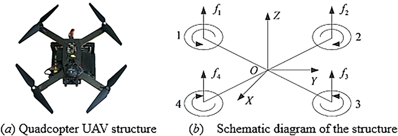
Figure 1: Quadcopter UAV
The mathematical model of the quadcopter UAV contains four parts: the power system model, control system model, attitude dynamics model, and position dynamics model. The power system model describes the lift force generated by the UAV during flight, the magnitude of the rotor torsional moment, the magnitude of the backward tilting moment, and the relationship between the drag force and propeller speed. The control system model describes the four control states of aircraft pitch, roll, yaw, and throttle. The attitude dynamics model and position dynamics model describe the changes in the attitude and position of the aircraft in the air. The input-output relationship between the model data consists of four parts (Fig. 2), and the motor speed is obtained according to the linear relationship between the lift generated by the propeller and motor speed. The control variables of the aircraft were obtained from the UAV flight state. Using the Newton-Euler formula, the kinematics and dynamics models of the UAV composed of lift and bending moments are derived, and a mathematical model of the UAV is established. To simplify the model, the following assumptions were made for a quadrotor UAV [8]:
1) The center of mass of the quadrotor UAV coincided with the geometric center.
2) Any component in a quadrotor UAV is a geometrically symmetric rigid structure with constant rotational inertia.
3) The plane of lift generated by paddle waving and the center of gravity lie in the same plane.
4) The square of the motor speed is proportional to the lift and counter torque generated by the propeller.

Figure 2: Input-output relationships between models
The coordinate systems in Fig. 3 are the inertial coordinate system and body coordinate system. The inertial coordinate system is the northeast celestial coordinate system, and the coordinate axes coincide with the east, north, and celestial directions of Earth. The body coordinate system is a coordinate system with the center of the UAV as the origin, pointing to the nose, right side of the body, and directly above the body.
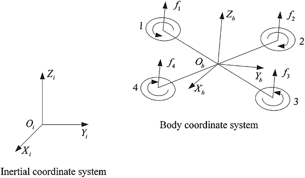
Figure 3: The coordinate systems
The variables are transferred from the b-system to the i-system by using Eq. (1), where
The power system model includes the ESC, motor, and propeller. When the pulse-width modulation (PWM) signal is input to the ESC controller, it passes through the controller inside the ESC and then outputs the voltage, which in turn controls the motor speed. When the ESC receives the drive signal, there is a delay, and the motor does not reach the target speed immediately, simplifying the process to a first-order inertial link:
where
It is assumed that a linear relationship exists between the PWM signal and the corresponding speed of the actual motor.
where
The control system model is used to describe the four control states of aircraft pitch, roll, yaw, and ascent or descent, and its mathematical model depends on the UAV structure. This study adopts the “x” structure UAV, which is subject to gravity, tension, and moment. Among them, the pull force is the vertical upward force generated by the rotation of the propeller-driven by the rotation of the motor; the torque is composed of the lifting moment generated by the rotation of the rotor, the counter-torque of the rotor, and the gyroscopic moment generated by the rotor advancement of the motor. The above pull force produces acceleration in three directions and the moment produces rotation in three directions. The gravity force on the UAV in the body coordinate system is:
where
Based on the fact that the lift force generated by the propeller is linearly related to the motor speed, the pull force generated by a single motor is:
where
Thus, the sum of the pull forces generated by the four motors is:
Similarly, the torque generated by the four individual motors in the yaw direction can be expressed as:
where
In addition to the moments generated in the yaw direction, there are four motors whose pull force causes the center of the drone to generate moments. Each motor’s steering is different to produce a moment in different directions, and the moment produced by the four motors in the direction of the traverse roll can be expressed as:
where
where
Then, the total torque generated by the four motors can be expressed as:
The dynamics model includes an attitude dynamics model and a position dynamics model, which describe the changes in the UAV’s position and attitude in the air, respectively. A quadrotor UAV is an underdriven system with six state variables
where I is the moment of inertia of the body, which can be experimentally measured using the following expression:
The acceleration of the UAV consists of the tensile and gravitational forces from the motors, and the expression of the dynamic equation for its position is:
where
4 Design of a Quadcopter UAV Controller
4.1 Structure of the Controller
The existing PID algorithm is a simple linear combination of control methods, and it is difficult to obtain efficient and high-precision control when controlling a multi-input-output underdriven system, such as a quadrotor UAV. While parameter tuning is a key link in the design of PID control systems, the traditional PID method not only requires the system to be tilted to the desired value in parameter tuning to satisfy the accuracy but also suppresses the overshoot and vibration to satisfy the stability. In this study, a DCLIPID controller was designed for the position and attitude controllers, and the overall structure of the controller is shown in Fig. 4, where the user releases the desired position. The sensor calculates the current position of the UAV and sends it to the position controller, and sends the desired roll angle, pitch angle, and total pull force to the attitude controller and the control distributor. The desired motor speed is then calculated using the attitude controller and sent to the control distributor to control the flight of the UAV.
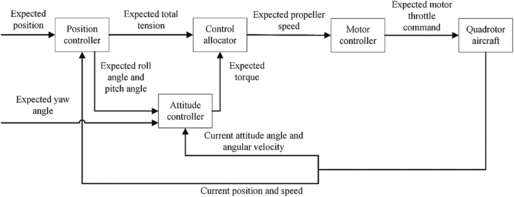
Figure 4: Overall structure of the controller
4.2 Design of Position Controller
The position loop of the DCLIPID controller replaces the P-controller of the outer loop with a nonlinear controller, which in this study is a hyperbolic tangent function. Its nonlinear characteristics can effectively reduce the control error and provide a better control effect for quadrotor UAVs. The inner loop is controlled by PID control and the outer loop is controlled to form a serial control of the position loop, and the PID algorithm [36] is:
The P term plays the main control role, and the output is proportional to the error. I is the integral term, which eliminates the static error by integrating the error. D is the differential term, which mainly adds damping to the system. A schematic of the position controller design is shown in Fig. 5.

Figure 5: Schematic structure of the position controller
4.3 Attitude Controller Design
The outer ring of the attitude loop in the DCLIPID controller uses hyperbolic tangent function and the inner ring uses intelligent PID control algorithm, which consists of two parts: intelligent control and PID control. The input variables of the humanoid intelligent controller are the error and the amount of error variation, and these two variables are computed to induce variables that can express other characteristics, providing more characteristic information for designing the DCLIPID controller. A typical step response curve has time t as the independent variable as a function of
The prototype formula [37] for the humanoid intelligent algorithm is as follows:
where e is the system error,
Based on the theoretical derivation above, the error e and error transformation amount
1) When
2) When
3) When
4) When
5) When
6) When
7) When
Taking the error e and error variation

Figure 6: Schematic diagram of the attitude controller structure
The system control is divided into three phases bounded by Mmin and Mmax, and the control strategy is based on the magnitude of the error and error derivatives to rectify the PID parameters. The implementation is divided into the following three steps:
1) Characterize the state of the system
2) Control modes
3) Strategy selection
Based on the mathematical derivation above, it is concluded that the UAV will produce different errors and error change rates when receiving different signals, at which time the UAV will choose different strategies to carry out the most suitable control mode for the current situation, and then use numerical simulation to verify the effectiveness of the program.
5 Numerical Simulation Analysis
The Simulink model of the quadcopter UAV and the DCLIPID controller were constructed in MATLAB for simulation test analysis. The structural design of the control system based on the serial PID method is illustrated in Fig. 7. A step signal and sine wave signal are fed to the controller to test the delay time, overshoot, and tracking of the controller, respectively, and compared with the serial PID method under the same conditions.

Figure 7: Control system structure of DCLIPID
In the design of the control system based on the PID method, the first consideration is how to design the control inputs of the system by defining a set of virtual control input variables as follows:
Combined with the quadcopter UAV model, the actual control inputs can be obtained as [4]:
The left reference inputs in Fig. 7 are three step signals, three sinusoidal signals, and the resulting desired quadrotor attitude value can be denoted as


The numerical simulation results obtained based on MATLAB are shown in Fig. 8, where a), b), c) denote the tracking of the quadrotor UAV in the X-direction, Y-direction, and Z-direction when the reference signal is a step signal; d), e), f) denote the tracking of the quadrotor UAV in the X-direction, the Y-direction, and the Z-direction when the reference signal is a sine wave signal. The black and green lines in Fig. 8 indicate the step reference signal and the sinusoidal reference signal, respectively; the blue and red lines indicate the tracking of the reference signal by the serial PID controller and the DCLIPID controller, respectively.
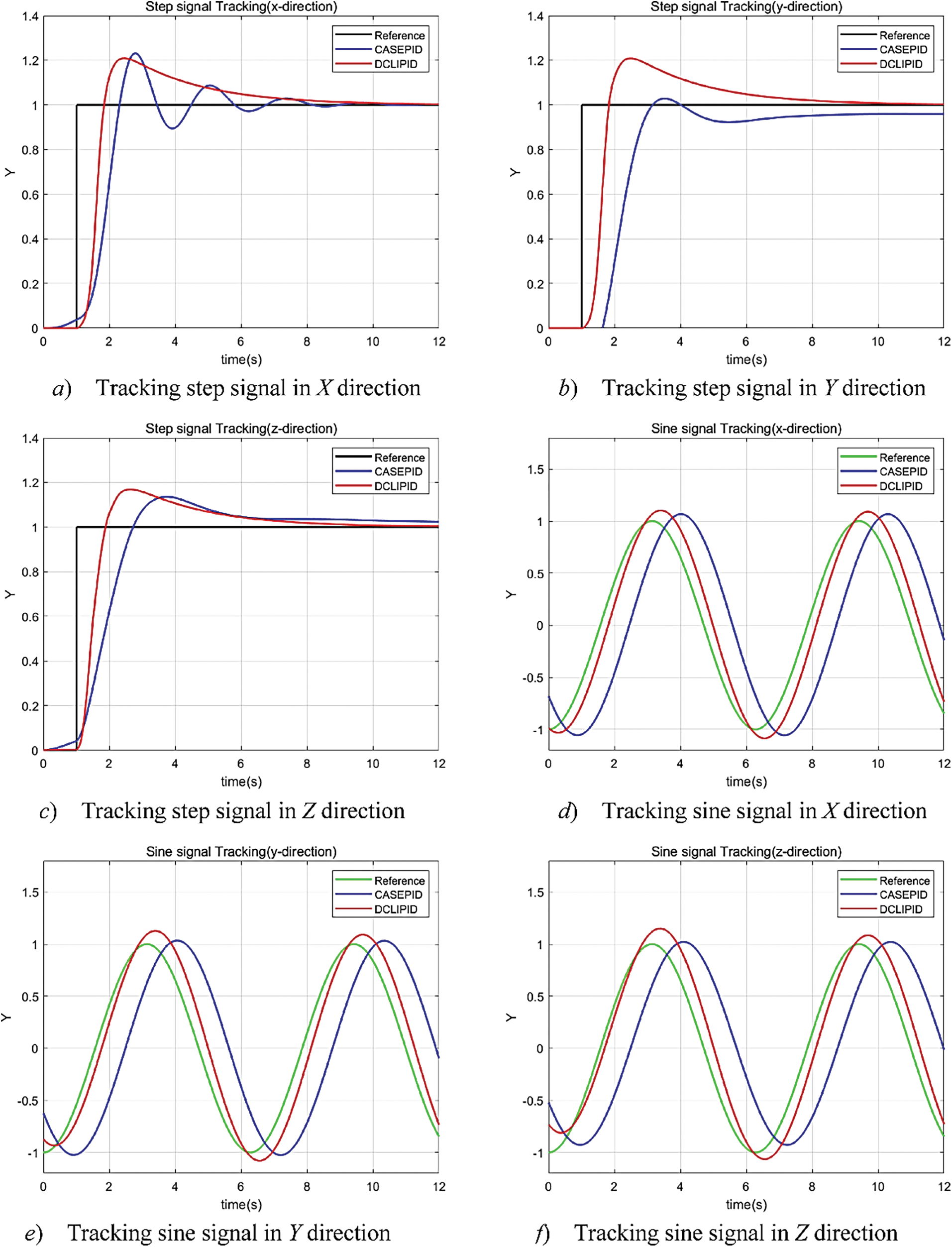
Figure 8: Simulation results of the control system
When a step signal is input, in Fig. 8a, the rise time of the step response of the DCLIPID and serial PID controllers are 0.75 and 0.95 s, the overshoot is 20% and 23%, and the number of oscillations are 1 and 3, respectively; in Fig. 8b, the rise time is 0.70 and 1.5 s, the overshoot is 20% and 5%, and the number of oscillations are 1, respectively; in Fig. 8c graph, the rise times are 0.8 and 1.3 s, the overshoots are 20% and 18%, and the number of oscillations are all 1 time. When a sinusoidal signal is input, the time delays of the DCLIPID and serial PID controllers are 0.30 and 1.0 s in Fig. 8d, and the maximum error values are 0.08 and 0.10, respectively; in Fig. 8e, the time delays are 0.10 and 1.2 s, and the maximum error values are 0.03 and 0.1, respectively; in Fig. 8f, the time delays are 0.30 and 1.3 s, the maximum error values are 0.04 and 0.12, respectively.
The MATLAB simulation test results show that when a step signal is input, the cascade PID method has an average longer rise time of 0.50 s and two more oscillations in the three directions than the DCLIPID method. When a sinusoidal signal is input, the cascade PID method has an average delay of 0.63 s more than the DCLIPID method in the three directions, the maximum error value is 0.056 more, and the overall effect is somewhat worse than that of the DCLIPID controller. Therefore, the DCLIPID control has more stable and accurate response characteristics than the cascade PID control.
6 Quadcopter UAV Experimental Design
6.1 Test Platform Construction
A four-axis, 400 mm wheelbase aircraft is used, the control system of this UAV is developed based on the STM32F103 processor with a main frequency of 72 MHz. The attitude control system mainly uses two ICM20689 IMUs as sensors. The hardware equipment includes the remote control, ground station (Q Ground Control, QGC) and the quadrotor UAV equipped with the control system, the test system realizes the communication between the ground and the ground using data transmission, the overall system of the aircraft is shown in Fig. 9. The quadrotor frame used in the flight test was made of carbon fiber, and the hardware parameters are listed in Table 3. The sensors built into the flight controller, such as the level, gyroscope, and magnetic compass, need to be calibrated before the UAV flies to ensure that it can fly properly. NVIDIA Nano represents a top-tier embedded computing platform designed for high-performance applications. This device connects to the flight controller via a serial port and employs the MAVLINK protocol to transmit the controller’s status in real time, as well as to receive commands from upper layers. By offering an efficient and flexible means for UAVs to validate control algorithms, the Nano accelerates the development process and experimental validation, which ultimately contributes to a more streamlined algorithm development process.
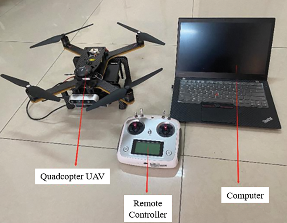
Figure 9: UAV control test system

6.2 Autonomous Trajectory Planning Experiment
Without giving a specific trajectory, the UAV power-up position is taken as the origin, and the designated spatial coordinate point is taken as the target point for the UAV to plan itself to the target position, and the flight strategy is as follows:
1) The outdoor flight environment is shown in Fig. 10.
2) Take the UAV power-up position as the origin and specify the spatial position (5, 5, 5) in metres.
3) Using autonomous control, the UAV is allowed to fly autonomously by cutting into offboard mode using remote control.
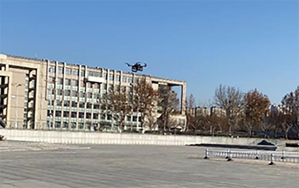
Figure 10: Outdoor flight environment
The trajectory test data of the UAV planning to the target position by itself is shown in Fig. 11, and the red, green, and blue lines indicate the flight trajectories of the traditional PID, serial PID, and DCLIPID control algorithms, respectively.
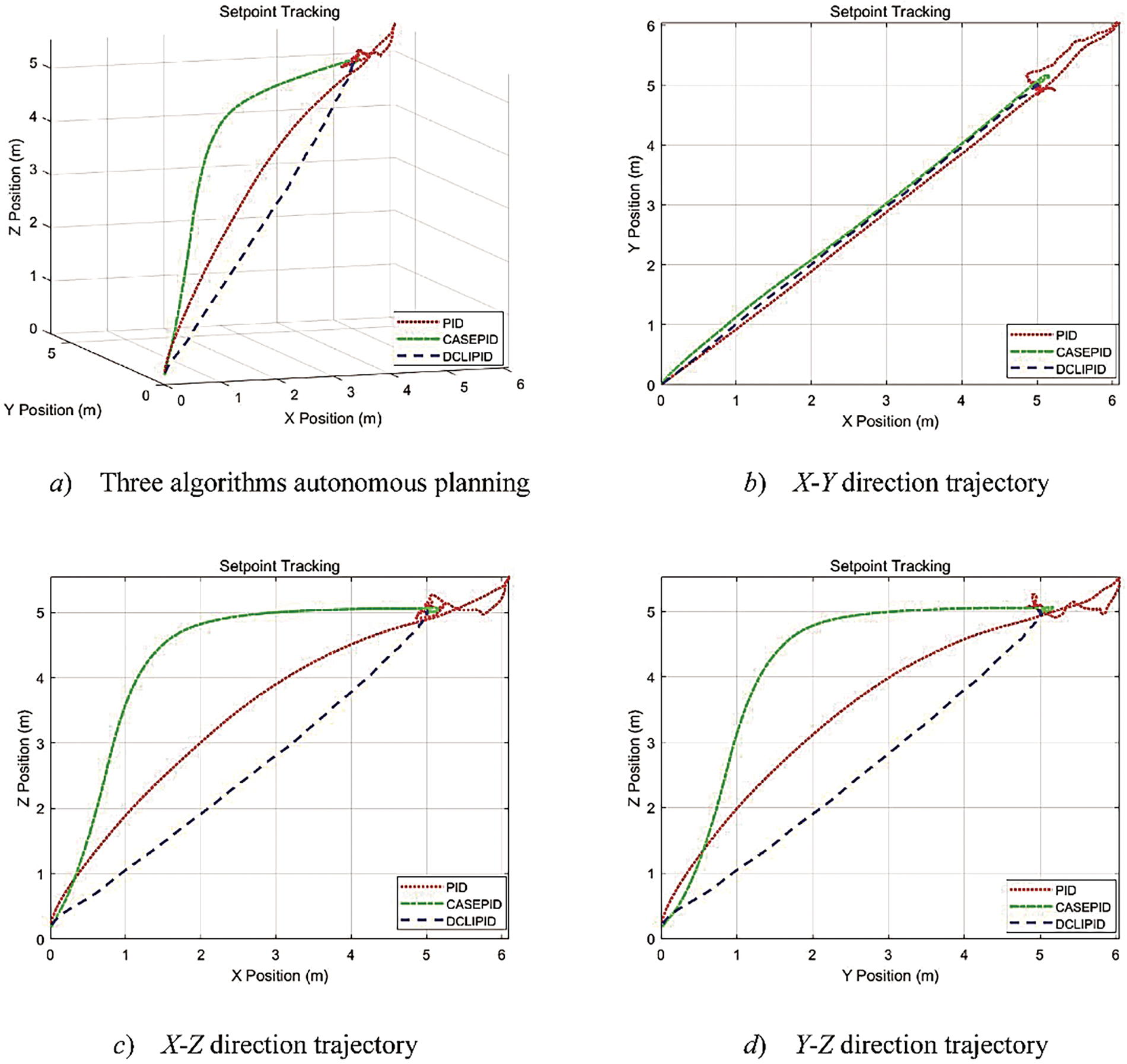
Figure 11: UAV autonomous planning trajectory data
Under the conditions of natural wind level 2, this test was conducted for a total duration of 45 s, during which the UAV position changed. As depicted in Fig. 11a, the trajectories planned by the three methods—DCLIPID, cascade PID, and PID—all led to the desired position, but their trajectories, time spent, and accuracy differed. The trajectory planned by DCLIPID was the most efficient, taking only 15.5 s and maintaining an error fluctuation between 0.1 and 0.3 m upon arrival at the target point. The trajectory planned by cascade PID, though longer than PID, had a negligible overshoot upon arrival at the target point, taking 22.3 s and maintaining an error fluctuation between 0.2 and 0.4 m. Finally, the trajectory planned by PID was the shortest but had a significant overshoot after reaching the target point, taking 39 s and maintaining an error fluctuation between 0.6 and 1 m. The experimental results demonstrate that the accuracy of the double-closed-loop intelligent control method is significantly higher than that of traditional PID and cascade PID methods.
A fan was used to simulate the artificial wind disturbance, and the fixed-point mode was set by remote control to allow the UAV to hover in the wind field, which is described as follows:
1) The indoor flight environment is shown in Fig. 12.
2) Take the UAV power-up position as the starting point, and specify the position in meters at the spatial location (0, 0, 2) in meters.
3) After the drone hovers, the wind speed of the control fan is gradually increased, and the wind speed produced by the electric fan ranges from:
4) Using fixed-point control, remote control is used to enter the fixed-point mode; in this state, let the drone hover at the specified space position.
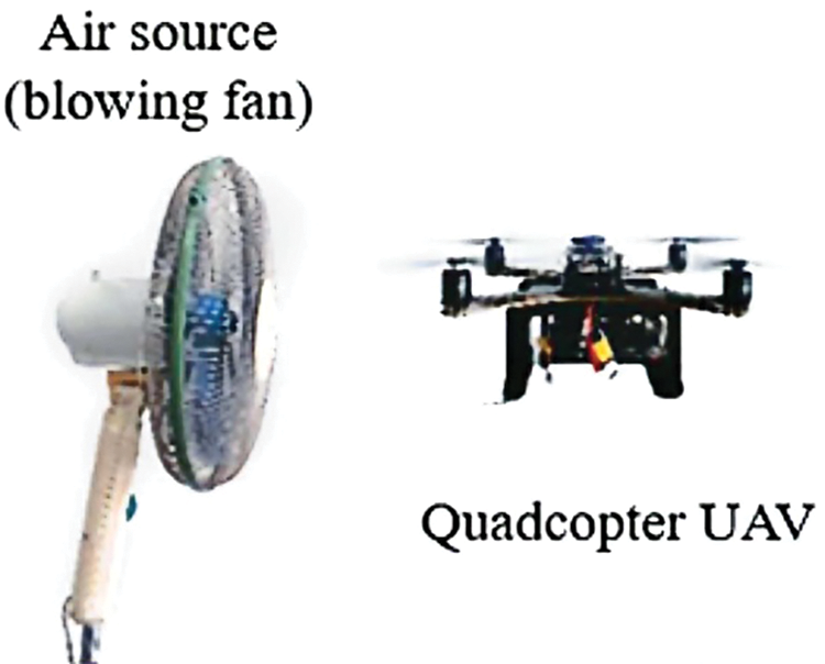
Figure 12: Indoor flight environment
With the addition of an artificial wind field, the hovering trajectory data of the three algorithms, traditional PID, cascade PID, and DCLIPID, are shown in Fig. 13a–d denote the curves of the three algorithms in the X-, Y-, and Z-directions, respectively, of the UAV’s positional data with respect to time. The red line indicates the tracking of the PID algorithm, the green line indicates the control of the cascade PID algorithm, and the blue dotted line indicates the control of the DCLIPID algorithm.

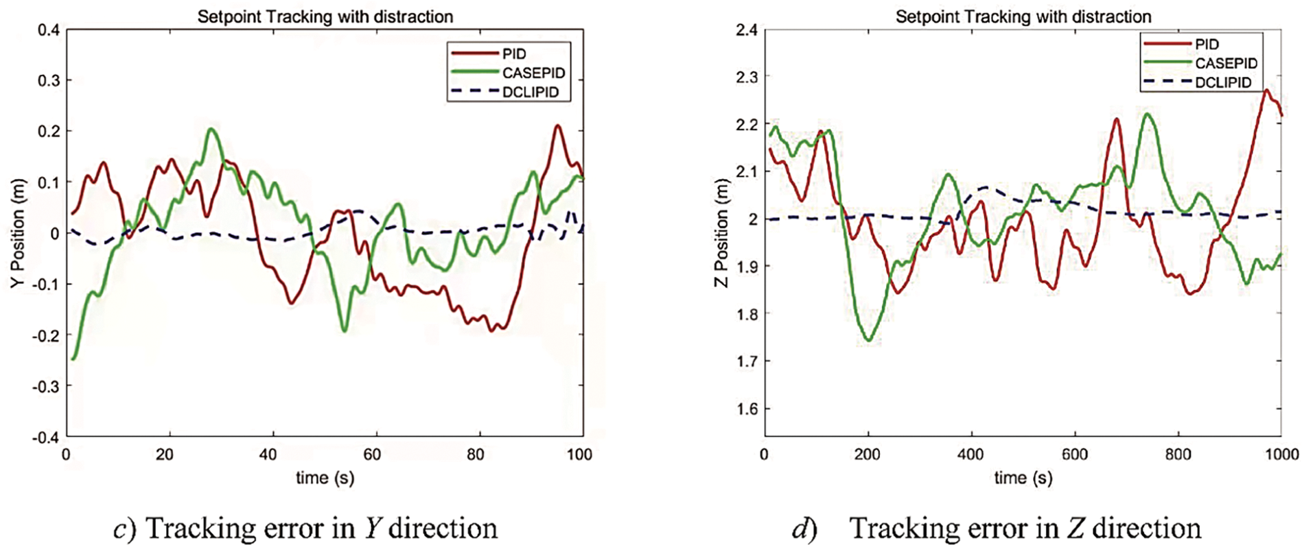
Figure 13: Hovering error in three directions under artificial wind disturbance
As can be seen from Fig. 13, in the case of artificial wind interference, the total length of the test is 100 s, and the difference between the current position
where

It is found that in the level 1 wind (wind speed 1 m/s), the traditional PID and cascade PID algorithms have obvious fluctuations, oscillating at about 0.2 m, while the DCLIPID algorithm fluctuates at about 0.05 m. Compared with the traditional PID method, the errors of the UAV in the X-, Y-, and Z- directions are reduced by 0.21, 0.15, and 0.21 m, respectively. Compared with the cascade PID method, the errors of the UAV in the X-, Y-, and Z-directions were reduced by 0.07, 0.06, and 0.09 m, respectively.
When the wind speed increases to 2.5 m/s at 40 s, the traditional PID algorithm starts to disperse gradually, and the fluctuation of the cascade PID algorithm is more obvious, oscillating at approximately 0.3 m; The fluctuation of the DCLIPID algorithm oscillates at approximately 0.1 m, and compared with the cascade PID method, the error of the UAV in the X-, Y-, and Z-directions is reduced by 0.12, 0.11, and 0.13 m, respectively. When the wind speed increased to 3.6 m/s at 90 s, the cascade PID algorithm began to disperse, and the UAV gradually became out of control. The DCLIPID algorithm fluctuations in the Y-direction also gradually began to disperse, but the vibrations in the X- and Z-directions were still controllable. Experimental results show that the anti-interference ability of the DCLIPID algorithm is significantly higher than that of the traditional and serial PID algorithms.
In this study, a DCLIPID control algorithm is innovatively proposed by combining humanoid intelligence and a serial PID algorithm, and the effectiveness of this method is verified by MATLAB numerical simulation and quadrotor UAV flight experiments. The main conclusions are as follows:
(1) The mathematical model of the quadrotor UAV is constructed according to the principle of flight, the error rate of change is introduced into the input of the serial PID controller, the error and the error rate of change are used as the characteristic variables of the UAV control system, and the hyperbolic tangent function is utilized to improve the outer-loop control of the controller, and a dual closed-loop humanoid intelligent PID (DCLIPID) control algorithm is innovatively proposed.
(2) Based on MATLAB, the Simulink model of the quadcopter UAV and the DCLIPID controller were constructed and analyzed in simulation tests, and the results showed that the rise time of the DCLIPID algorithm was reduced by 0.50 s and the number of oscillations was reduced by 2 times in comparison with that of the cascade PID algorithm.
(3) A quadrotor UAV controller test system was built and flight tests were conducted. The results of the autonomous planning trajectory test show that the error of the UAV in the X-, Y-, and Z-directions is reduced by 0.22, 0.21, and 0.31 m, respectively, in comparison with the string-level PID algorithm. The anti-interference test results show that, compared with the cascade PID algorithm, the cascade PID controller gradually diverged under an artificial wind of approximately 3.6 m/s, and the DCLIPID controller was still able to maintain hovering; at this time, the UAV’s hovering errors in the X-, Y-, and Z-directions were 0.24, 0.42, and 0.27 m, respectively.
The simulation and experimental results verify that the dual closed-loop humanoid intelligent PID (DCLIPID) control algorithm can improve the real-time performance, control accuracy, and anti-jamming ability of UAV, and the method has a certain reference value for research in the field of UAV control.
Acknowledgement: This research was supported by the School of Mechanical Engineering, Hebei University of Science and Technology, Shijiazhuang, China.
Funding Statement: This research was supported by the Scientific Research Projects of Higher Education Institutions in Hebei Province (Grant No. QN2023188), and the project of Hebei University of Science and Technology (Grant No. 1200752).
Author Contributions: The authors confirm the contribution to the paper as follows: study conception: Jianshu Liang, Linlin Zhang; data collection: Lvzhao Bai, Yuejing Zhao, Zhiying Qin; analysis and writing: Linlin Zhang, Lvzhao Bai, Jianshu Liang. Revisions were done by Jianshu Liang and Zhiying Qin. All authors reviewed the results and approved the final version of the manuscript.
Availability of Data and Materials: The authors confirm that the data supporting the findings of this study are available within the article.
Ethics Approval: Not applicable.
Conflicts of Interest: The authors declare that they have no conflicts of interest to report regarding the present study.
References
1. C. D. Mckinnon and A. P. Schoellig, “Estimating and reacting to forces and torques resulting from common aerodynamic disturbances acting on quadrotors,” Robot. Auton. Syst., vol. 123, no. 4, Jan. 2020, Art. no. 103314. doi: 10.1016/j.robot.2019.103314. [Google Scholar] [CrossRef]
2. W. J. Cai, J. H. She, M. Wu, and Y. Ohyama, “Disturbance suppression for quadrotor UAV using sliding-mode-observer-based equivalent-input-disturbance approach,” ISA Trans., vol. 92, no. 3, pp. 286–297, Sep. 2019. doi: 10.1016/j.isatra.2019.02.028. [Google Scholar] [PubMed] [CrossRef]
3. P. Lyu, B. Wang, J. Lai, S. C. Liu, and Z. M. Li, “A drag Model-LIDAR-IMU fault-tolerance fusion method for quadrotors,” Sensors, vol. 19, no. 19, Oct. 2019, Art. no. 4337. doi: 10.3390/s19194337. [Google Scholar] [PubMed] [CrossRef]
4. M. Abdolhosseini, Y. M. Zhang, and C. A. Rabbath, “An efficient model predictive control scheme for an unmanned quadrotor helicopter,” J. Intell. & Robot. Syst., vol. 70, no. 1–4, pp. 27–38, Apr. 2013. doi: 10.1007/s10846-012-9724-3. [Google Scholar] [CrossRef]
5. S. Bouabdallah, A. Noth, and R. Siegwart, “PID vs LQ control techniques applied to an indoor micro quadrotor,” in Proc. IEEE/RSJ Int. Conf. Intell. Robots & Syst., Sep. 2004, pp. 2451–2456. doi: 10.1109/IROS.2004.1389776. [Google Scholar] [CrossRef]
6. B. K. Singh and A. Kumar, “Model predictive control using LPV approach for trajectory tracking of quadrotor UAV with external disturbances,” Aircr. Eng. Aerosp. Technol., vol. 95, no. 4, pp. 607–618, Feb. 2023. doi: 10.1108/AEAT-12-2021-0368. [Google Scholar] [CrossRef]
7. H. T. Zhen, X. H. Qi, J. Li, and L. J. Su, “Quadrotor UAV L1 adaptive block backstepping attitude controller,” Contr. Decis., vol. 29, no. 6, pp. 1076–1082, Apr. 2014. doi: 10.13195/j.kzyjc.2013.0353. [Google Scholar] [CrossRef]
8. T. Ryan and H. J. Kim, “LMI-based gain synthesis for simple robust quadrotor control,” IEEE Trans. Autom. Sci. & Eng., vol. 10, no. 4, pp. 1173–1178, Oct. 2013. doi: 10.1109/TASE.2013.2259156. [Google Scholar] [CrossRef]
9. Z. A. Ansari and G. L. Raja, “Flow direction optimizer tuned robust FOPID-(1+TD) cascade controller for oscillation mitigation in multi-area renewable integrated hybrid power system with hybrid electrical energy storage,” J. Energy Storage, vol. 83, no. 1, Apr. 2024, Art. no. 110616. doi: 10.1016/j.est.2024.110616. [Google Scholar] [CrossRef]
10. Y. F. Hanna, A. A. Khater, M. El-Bardini, and A. M. El-Nagar, “Real time adaptive PID controller based on quantum neural network for nonlinear systems,” Eng. Appl. Artif. Intell., vol. 126, Nov. 2023, Art. no. 106952. doi: 10.1016/j.engappai.2023.106952. [Google Scholar] [CrossRef]
11. C. Sun, M. Liu, C. Liu, X. L. Feng, and H. Wu, “An industrial quadrotor UAV control method based on fuzzy adaptive linear active disturbance rejection control,” Electronics, vol. 10, no. 4, Feb. 2021, Art. no. 376. doi: 10.3390/ELECTRONICS10040376. [Google Scholar] [CrossRef]
12. V. Kumar and N. Michael, “Opportunities and challenges with autonomous micro aerial vehicles,” Int. J. Rob. Res., vol. 31, no. 11, pp. 1279–1291, Sep. 2012. doi: 10.1177/0278364912455954. [Google Scholar] [CrossRef]
13. I. Lopez-Sanchez and J. Moreno-Valenzuela, “PID control of quadrotor UAVs: A survey,” Annu. Rev. Control, vol. 56, no. 3, Jul. 2023, Art. no. 100900. doi: 10.1016/j.arcontrol.2023.100900. [Google Scholar] [CrossRef]
14. P. Zarafshan, S. A. A. Moosavian, and M. Bahrami, “Comparative controller design of an aerial robot,” Aerosp. Sci. Technol., vol. 14, no. 4, pp. 276–282, Jun. 2010. doi: 10.1016/j.ast.2010.01.001. [Google Scholar] [CrossRef]
15. Y. Zou, “Nonlinear robust adaptive hierarchical sliding mode control approach for quadrotors,” Int. J. Robust & Nonlinear Control, vol. 27, no. 6, pp. 925–941, Apr. 2017. doi: 10.1002/rnc.3607. [Google Scholar] [CrossRef]
16. J. J. Xiong and G. B. Zhang, “Global fast dynamic terminal sliding mode control for a quadrotor UAV,” ISA Trans., vol. 66, no. 3, pp. 233–240, Jan. 2017. doi: 10.1016/j.isatra.2016.09.019. [Google Scholar] [PubMed] [CrossRef]
17. Y. Zhang, Z. Chen, and X. Zhang, “A novel control scheme for quadrotor UAV basedupon active disturbance rejection control,” Aerosp. Sci. Technol., vol. 79, no. 7, pp. 601–609, Aug. 2018. doi: 10.1016/j.ast.2018.06.017. [Google Scholar] [CrossRef]
18. W. Gu, K. P. Valavanis, M. J. Rutherford, and A. Rizzo, “UAV model-based flight control with artificial neural networks: A survey,” J. Intell. & Robot. Syst., vol. 100, no. 3–4, pp. 1469–1491, Sep. 2020. doi: 10.1007/s10846-020-01227-8. [Google Scholar] [CrossRef]
19. S. Wen, Q. Y. Zhang, X. C. Yin, Y. B. Lan, J. T. Zhang and Y. F. Ge, “Design of plant protection UAV variable spray system based on neural networks,” Sensors, vol. 19, no. 5, Mar. 2019, Art. no. 1112. doi: 10.3390/s19051112. [Google Scholar] [PubMed] [CrossRef]
20. M. Rabah, A. Rohan, M. H. Haghbayan, J. Plosila, and S. H. Kim, “Heterogeneous parallelization for bbject detection and tracking in UAVs,” IEEE Access, vol. 8, no. 99, pp. 42784–42793, Feb. 2020. doi: 10.1109/ACCESS.2020.2977120. [Google Scholar] [CrossRef]
21. C. P. Bechlioulis and G. A. Rovithakis, “Prescribed performance adaptive control of SISO feedback linearizable systems with disturbances,” in Proc. IEEE Mediterr. Conf. Control Autom., Jun. 2008, pp. 1035–1040. doi: 10.1109/MED.2008.4601971. [Google Scholar] [CrossRef]
22. S. S. Yu, X. Fan, J. J. Qi, L. F. Wan, and B. Y. Liu, “Attitude control of quadrotor UAV based on integral backstepping active disturbance rejection control,” Trans. Inst. Meas. Contr., vol. 46, no. 4, pp. 703–715, Feb. 2024. doi: 10.1177/01423312231185423. [Google Scholar] [CrossRef]
23. C. C. Hua, J. N. Chen, and X. Guan, “Adaptive prescribed performance control of QUAVs with unknown time-varying payload and wind gust disturbance,” J. Franklin Inst., vol. 355, no. 14, pp. 6323–6338, Sep. 2018. doi: 10.1016/j.jfranklin.2018.05.062. [Google Scholar] [CrossRef]
24. G. L. Zhao, R. S. Gao, and J. N. Chen, “Adaptive prescribed performance control of quadrotor with unknown actuator fault,” Contr. Decis., vol. 36, no. 9, pp. 2103–2112, Sep. 2021. doi: 10.13195/j.kzyjc.2020.0083. [Google Scholar] [CrossRef]
25. T. Deng et al., “A VR-based BCI interactive system for UAV swarmcontrol,” Biomed. Signal Process. Control, vol. 85, Apr. 2023, Art. no. 104944. doi: 10.2139/ssrn.4251135. [Google Scholar] [CrossRef]
26. T. D. M. Sanguino and J. M. L. Dominguez, “Design and stabilization of a Coanda effect-based UAV: Comparative study between fuzzy logic and PID control approaches,” Robot. Auton. Syst., vol. 175, May 2024, Art. no. 104662. doi: 10.1016/j.robot.2024.104662. [Google Scholar] [CrossRef]
27. N. Bernini et al., “Reinforcement learning with formal performance metrics for quadcopter attitude control under non-nominal contexts,” Eng. Appl. Artif. Intell., vol. 127, Jan. 2024, Art. no. 107090. doi: 10.1016/j.engappai.2023.107090. [Google Scholar] [CrossRef]
28. B. Wang, Y. Zhang, and W. Zhang, “Integrated path planning and trajectory tracking control for quadrotor UAVs with obstacle avoidance in the presence of environmental and systematic uncertainties: Theory and experiment,” Aerosp. Sci. Technol., vol. 120, Jan. 2022, Art. no. 107277. doi: 10.1016/j.ast.2021.107277. [Google Scholar] [CrossRef]
29. J. R. Ren, Q. Quan, H. B. Ma, and K. Y. Cha, “Additive-state-decomposition-based station-keeping control for autonomous aerial refueling,” Sci. China-Inf. Sci., vol. 64, no. 11, Jul. 2020, Art. no. 219202. doi: 10.1007/s11432-019-2814-x. [Google Scholar] [CrossRef]
30. K. Ahmadi, D. Asadi, A. Merheb, S. Y. Nabavi-Chashmi, and O. Tutsoy, “Active fault-tolerant control of quadrotor UAVs with nonlinear observer-based sliding mode control validated through hardware in the loop experiments,” Control Eng. Pract., vol. 137, 2023, Art. no. 105557. doi: 10.1016/j.conengprac.2023.105557. [Google Scholar] [CrossRef]
31. K. Ahmadi, D. Asadi, S. Y. Mabavi-Chashmi, and O. Tutsoy, “Modified adaptive discrete-time incremental nonlinear dynamic inversion control for quad-rotors in the presence of motor faults,” Mech. Syst. Signal Process., vol. 188, no. 1, 2023, Art. no. 109989. doi: 10.1016/j.ymssp.2022.109989. [Google Scholar] [CrossRef]
32. L. Zhou, A. Pljonkin, and P. K. Singh, “Modeling and PID control of quadrotor UAV based on machine learning,” Int. J. Intell. Syst. Int., vol. 31, no. 1, pp. 1112–1122, 2022. doi: 10.1515/jisys-2021-0213. [Google Scholar] [CrossRef]
33. D. Kang and Y. J. Cha, “Autonomous UAVs for structural health monitoring using deep learning and an ultrasonic beacon system with geo-tagging,” Comput. Aided Civ. Infrastruct. Eng., vol. 33, no. 10, pp. 885–902, May 2018. doi: 10.1111/mice.12375. [Google Scholar] [CrossRef]
34. R. Ali, D. Kang, G. Suh, and Y. J. Cha, “Real-time multiple damage mapping using autonomous UAV and deep faster region-based neural networks for GPS-denied structures,” Autom. Constr., vol. 130, 2021, Art. no. 103831. doi: 10.1016/j.autcon.2021.103831. [Google Scholar] [CrossRef]
35. A. Waqas, D. Kang, and Y. J. Cha, “Deep learning-based obstacle-avoiding autonomous UAVs with fiducial marker-based localization for structural health monitoring,” Struct. Health Monit., vol. 23, no. 2, pp. 971–990, 2024. doi: 10.1177/14759217231177314. [Google Scholar] [PubMed] [CrossRef]
36. B. J. Emran and H. Najjaran, “A review of quadrotor: An underactuated mechanical system,” Annu. Rev. Control, vol. 46, no. 1–4, pp. 165–180, Dec. 2018. doi: 10.1016/j.arcontrol.2018.10.009. [Google Scholar] [CrossRef]
37. Z. S. Li and Y. Q. Tu, Human-Simulated Intelligent Control. Beijing, China: National Defense Industry Press, 2003. [Google Scholar]
Cite This Article
 Copyright © 2024 The Author(s). Published by Tech Science Press.
This work is licensed under a Creative Commons Attribution 4.0 International License , which permits unrestricted use, distribution, and reproduction in any medium, provided the original work is properly cited.


 Submit a Paper
 Propose a Special lssue
 View Full Text
 Download PDF
 Downloads
 Citation Tools