
 Submit a Paper
 Propose a Special lssue
 Open Access
ARTICLE
An Optimized Approach for Spectrum Utilization in mmWave Massive MIMO 5G Wireless Networks
1 Faculty of Science, Northern Border University, Arar, Saudi Arabia
2 Faculty of Science, Tanta University, Tanta, Egypt
3 Computer Sciences Department, College of Computer and Information Sciences, Princess Nourah Bint Abdulrahman University, Riyadh, Saudi Arabia
4 Department of Mathematics, Faculty of Science, New Valley University, El-Kharga, 72511, Egypt
5 Faculty of Computers and Information, Tanta University, El-Giesh, Egypt
* Corresponding Author: Romany F. Mansour. Email:
Computer Systems Science and Engineering 2023, 47(2), 1493-1505. https://doi.org/10.32604/csse.2023.037976
Received 23 November 2022; Accepted 09 February 2023; Issue published 28 July 2023
 View Full Text
 Download PDF
Abstract
Massive multiple-input multiple-output (MIMO) systems that use the millimeter-wave (mm-wave) band have a higher frequency and more antennas, which leads to significant path loss, high power consumption, and server interference. Due to these issues, the spectrum efficiency is significantly reduced, making spectral efficiency improvement an important research topic for 5G communication. Together with communication in the terahertz (THz) bands, mmWave communication is currently a component of the 5G standards and is seen as a solution to the commercial bandwidth shortage. The quantity of continuous, mostly untapped bandwidth in the 30–300 GHz band has presented a rare opportunity to boost the capacity of wireless networks. The wireless communications and consumer electronics industries have recently paid a lot of attention to wireless data transfer and media streaming in the mmWave frequency range. Simple massive MIMO beamforming technology cannot successfully prevent interference between multiple networks in the current spectrum-sharing schemes, particularly the complex interference dispersed in indoor communication systems such as homes, workplaces, and stadiums. To effectively improve spectrum utilization and reduce co-channel interference, this paper proposes a novel algorithm. The main idea is to utilize the spectrum in software-defined mmWave massive MIMO networks through coordinated and unified management. Then, the optimal interference threshold is determined through the beam alignment method. Finally, a greedy optimization algorithm is used to allocate optimal spectral resources to the users. Simulation results show that the proposed algorithm improved spectral efficiency and reduced interference.Keywords
The design concept of the 5G millimeter-wave (mmWave) system is different from the traditional mobile communication system [1–5]. It focuses on wider multi-point distribution, multi-user communication, a multi-antenna system, and multi-cell cooperation [6–9], and strives to achieve system architecture, which seeks to greatly improve the system’s performance so that the system can provide a peak rate of more than 10 GB [10–14].
With the advent of 5G, the contradiction between the increasing demand for radio spectrum and the limited available spectrum in mobile communication systems has become increasingly prominent, and the use of spectrum-sharing technology can make the use of frequency resources more balanced in time and space [15–19]. In the 5G spectrum-sharing method, experts and scholars have proposed many implementation methods for spectrum-sharing technology [20]. One is to set the interference threshold and improve the spectrum efficiency by reusing the unlicensed spectrum of the primary user with the secondary user [21–25]. This method pre-sets the corresponding interference threshold, and when the interference value exceeds the threshold, the interference coordination is triggered [26–28]. During the interference coordination process, secondary users are prohibited from reusing the spectrum of primary users [29].
With a wide range of frequencies (sub-1 GHz to 100 GHz) and very large bandwidths, seamless carrier aggregation across multiple bands, a huge number of steerable antenna elements, and a flexible and scalable physical layer for handling various scenarios, 5G NR has dramatically increased the capabilities of cellular communication [30]. Non-public networks based on 5G-NR are becoming more common, particularly for industrial applications [31]. This is because 5G NR outperforms other current wireless technologies, such as Wi-Fi or 4G/LTE (long-term evolution), in terms of performance characteristics, mobility support, scalability, and security [32]. These technologies are unable to adequately satisfy the intended communication demands because of the demanding requirements of industrial applications [33]. There are several 5G NR non-public network deployment possibilities, including employing locally licensed spectrum or spectrum licensed for public operator networks, depending on the market. Compared to LTE/LTE-Advanced, NR can provide improved dependability, additional spectrum bands, lower latency, and faster data rates [34].
The other category is to use massive multiple-input multiple-output (MIMO) technology to achieve beamforming to reduce the radiation of electromagnetic waves in other directions and avoid interference [35]. Compared with the existing MIMO technology, the spatial resolution achieved by massive MIMO is significantly enhanced; it can deeply excavate the spatial dimension resources, realize spatial multiplexing, and also concentrate the beam width in a narrow range so that the main lobe direction of the beam formed by the electromagnetic wave emitted by the base station is aligned with the desired user direction [35], thereby greatly reducing the network cost and interference level.
Reference [36] discusses the potential advantages of using massive MIMO in the base station and user end of the spectrum-sharing network. Reference [37] establishes a multi-beam spatiotemporal super-resolution beamforming framework of massive MIMO technology, which can generate large gains in the beam-pointing direction and suppress co-channel interference. Reference [38] proposes a new massive MIMO spatial spectrum sharing strategy for cognitive radio (CR) and realizes spectrum sharing between multiple base stations through CR technology.
However, in the existing spectrum-sharing schemes, the simple massive MIMO beamforming technology cannot effectively avoid interference between different networks, especially the complex interference distributed in indoor communication systems such as residential areas, offices, and stadiums. To solve this problem, this paper uses a software-defined network (SDN) mmWave massive MIMO spectrum management solution to centralize the management of interference links between networks, combines gNB and UE beamforming technology to obtain the best interference threshold, simplifies the relationship between interference graphs, and optimizes the greedy algorithm. Then, allocate orthogonal spectrum resources for each interference link, to avoid the interference of inter-network links.
SDN separates the control plane from the data forwarding plane to realize programmatic control [39]. This paper designs a centralized SDN wireless link resource control layer coordinator (CLC), which is connected to each mmWave network, is responsible for the unified allocation and management of wireless link resources of each network and allocates available spectrum for each mmWave network link resource. Each mmWave network includes an SDN Basic Implementation Layer Coordinator (BILC) and an interference database (DB). The structure of the centralized SDN link interference management layer in this paper is shown in Fig. 1.
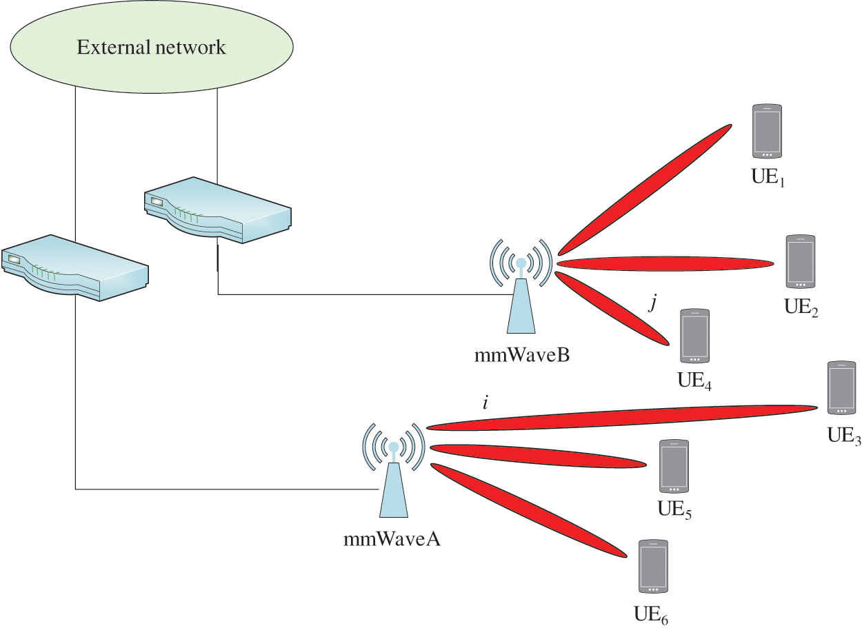
Figure 1: Centralized links interfere with the management layer structure
In each mmWave network, the DB stores the link interference information for the network, and the BILC is responsible for uploading the interference information in the DB to the CLC and at the same time receiving the coordination information issued by the CLC. In each network, the BILC uploads the interference information to the CLC, and the CLC constructs the interference graph of the interference links of each network, uses the greedy algorithm to color the interference graph, and realizes the re-planning of each network resource (time and frequency) allocation, assigning mutually orthogonal frequency bands to the interfered link spectral resources.
In the network shown in Fig. 2, there is co-channel interference between link i in the network mmWave and link j in the network mmWaveB located in the same area, and the interference coordination mechanism is triggered when the interference on the link i exceeds the maximum interference threshold. Coordination means that when the corresponding interfering link pair (link i of network mmWaveA and link j of network mmWaveB) use the same spectrum resources, the transmission is limited and the spectrum resources need to be reallocated. The two interfering networks carry out this resource division protocol and call the SDN control layer coordinator to reallocate the resources of the interfering link.
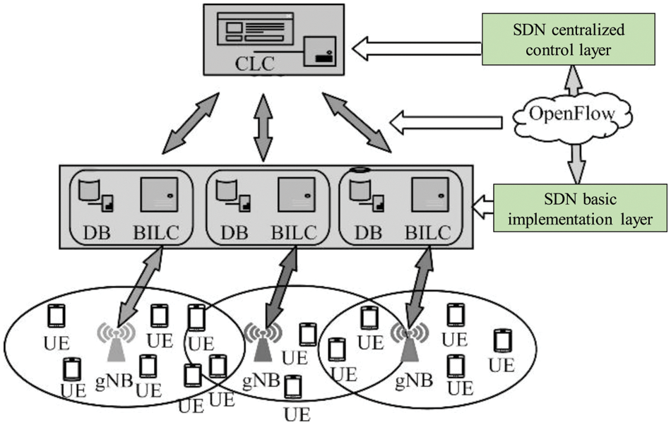
Figure 2: Schematic diagram of inter-network user link interference
Both the gNB side and the UE side adopt massive MIMO, and the transmitting end uses beamforming technology to generate a specific-angle beam pointing to the receiving end antenna to generate a specific-angle beam pointing to the transmitting end to obtain the optimal interference threshold. The schematic diagram of beam alignment between gNB and UE is shown in Fig. 3.
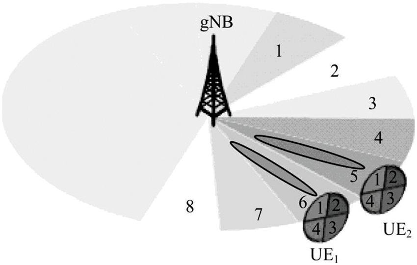
Figure 3: Schematic diagram of beam alignment between gNB and UE
The beamforming gain from transmitter i to receiver j can be expressed as:
Among them,
Simulate the MIMO channel model with K clusters, each cluster contains L subpaths, and the channel model
Among them,
Among them,
Small-scale fading is related to the number of clusters, number of subpaths, Doppler shift, power, delay spread, and angle of arrival (AoA).
The system link path loss and shading (in dB) are expressed as:
The beamforming channel interference can be expressed as:
Use formula (5) to calculate the interference value of each link to the target link and mark the maximum interference pair to form the basis of interference coordination decision-making at the control layer.
3 Proposed Algorithm Implementation
When the system uses the feedback mechanism, each network access point obtains the corresponding interference pair through interference measurement. According to the interference information fed back by each mmWave network, the CLC reallocates mutually orthogonal resources to the interfering links in the network to achieve coordinated management of spectrum interference between networks.
The specific steps of the process are:
Step 1: Interference detection between networks. Interference to user k of another network link and other mmWave networks is measured at the same time. The interference situation of the middle link j with its network link i. Each network stores the information about the interference link pair in the interference database of the network to form the basic conditions for the coordination decision of the interference link in the SDN control layer.
Step 2: Implementation Layer Interference Information Transmission. Compare the interference information measured in each mmWave network with the optimal interference threshold obtained above and remove the interference information in the DB whose interference value is smaller than the interference threshold, where each link’s interference information will be expressed as a link id (for example, the base station id + user id). Each mmWave network sends the measurement results to the BILC connected to it, and the BILC sends all received information sets that need to be coordinated to the CLC, which completes unified resource management and coordination.
Step 3: Control Layer Link Resource Allocation. Each BILC reports the interference link pair to the CLC, and the CLC establishes an interference graph through the relationship between the edge and the node. The edge
Satisfying
This paper simplifies the relationship of the graph by calculating the optimal interference threshold to color the interference graph, and the process is shown in Fig. 4.
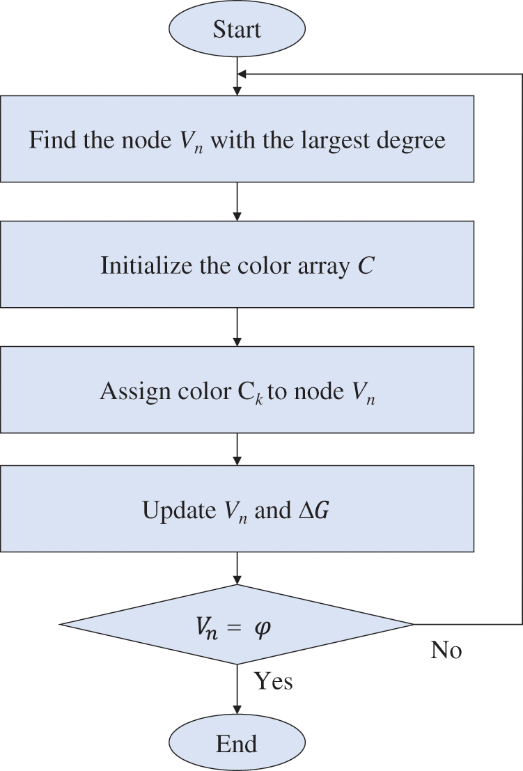
Figure 4: Optimal interference threshold algorithm flowchart
Using the above method to color the interference graph, the algorithm complexity is:
Step 4: Basic Implementation Layer Resource Scheduling. After the SDN control layer completes the coloring of the interference graph, the CLC needs to send the interference coordination result to each connected BILC, and the BILC sends the interference information to the corresponding gNB. When the gNB receives the interference coordination decision report, it will reset. If a link is not coordinated, the spectrum resource associated with the link will not be reallocated.
The system in this paper uses the network simulator NS-3 [41,42], the system frequency is 26 GHz, and its physical layer frame structure is similar to the LTE frame structure [43], with a frame length of 10 ms. Each frame is divided into 10 subframes with a length of 1 ms, and each subframe is divided into 8-time slots with a length of 125 s. In the frequency domain, the bandwidth of 1 GHz is divided into 4 resource blocks (RB), each of which is subdivided into 18 sub-bands with a width of 13.89 MHz, a total of 72 sub-bands, and each sub-band consists of 48 subcarriers.
The indoor environment is selected for the simulation, and a room with a length, width, and height of 6, 8, and 3 m is simulated to evaluate the link interference between networks in the indoor environment, as shown in Fig. 5, in which only part of the UE is drawn. In this environment, two different mmWave networks (mmWaveA and mmWaveB) are deployed, a total of 20 UEs are placed in the room, and each UE is randomly connected to a mmWave network. Set the UE in this scenario to move slowly at different speeds, and use this scenario to simulate the link interference between two different networks. When the beams in the two networks point to the same space and use the same spectrum resources at the same time, the feasibility and performance of this scheme are validated.
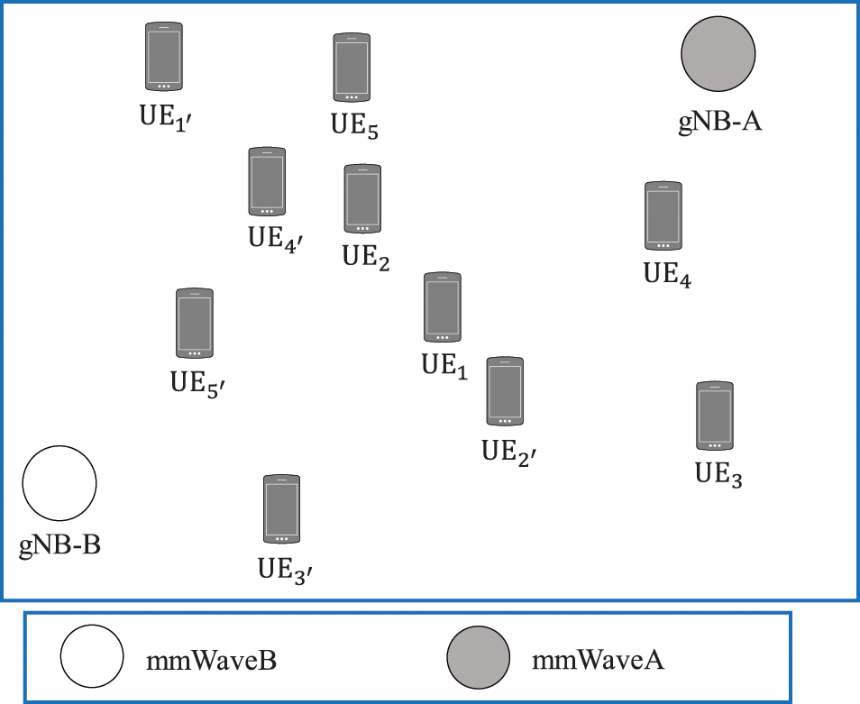
Figure 5: System simulation environment
When the link interference value exceeds the maximum interference threshold, the system does not trigger the SDN link interference coordination mechanism, and only uses massive MIMO beamforming technology to avoid link interference between different networks, that is, the array antenna generates beams pointing in different directions to users. Each beam uses different spectral resources to avoid mutual interference. However, in areas where users are densely distributed, the same-frequency beams of different gNBs may point to the same area, and users in this area will suffer from inter-network co-channel interference.
The above scenario is simulated, and the simulation results for mmWaveA and mmWaveB networks are shown in Figs. 6 and 7, respectively. Among them, link i where UE2 is located in the mmWaveA network, and link j where UE1 is located in the mmWaveB network, use the same spectrum resources. It can be seen from Fig. 6 that UE2 in the mmWaveA network suffers severe co-channel interference from the link of UE1 in the mmWaveB network, and the signal-to-noise ratio (SNR) of UE2 in the mmWaveA network is only about 2 dB, which is significantly smaller than that of the un-interference UE1 in the network. It can be seen from Fig. 7 that the link where UE1 is located in the mmWaveB network is also subject to co-channel interference from the link where UE2 is located in the mmWaveA network, and the SNR of UE3 is about 7 dB, whereas the link where UE2 is located, has serious SNR interference. With the continuous operation of the simulation program, the SNR of each user in the mmWaveA network and the mmWaveB network does not change significantly.
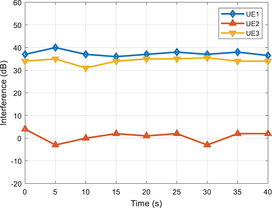
Figure 6: Link interference for each user in the mmWaveA network
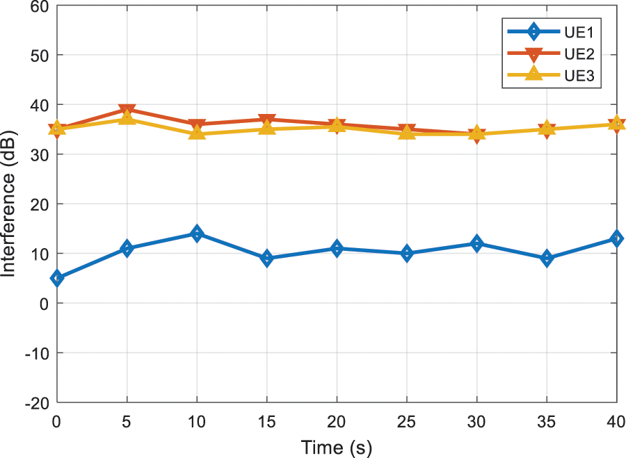
Figure 7: Link interference for each user in the mmWaveB network
In the case of keeping the above indoor simulation environment and related parameters unchanged, a specific link interference coordination scheme is added to the scene. When the link interference value is greater than the set interference threshold, the link interference coordination mechanism is triggered and the simulation is performed again. The results are as follows: Figs. 8 and 9.
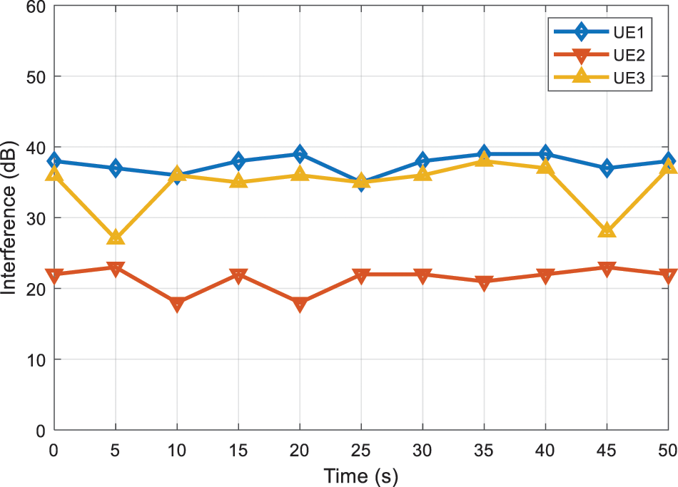
Figure 8: Simulation results of interference coordination for each link of the mmWaveA network
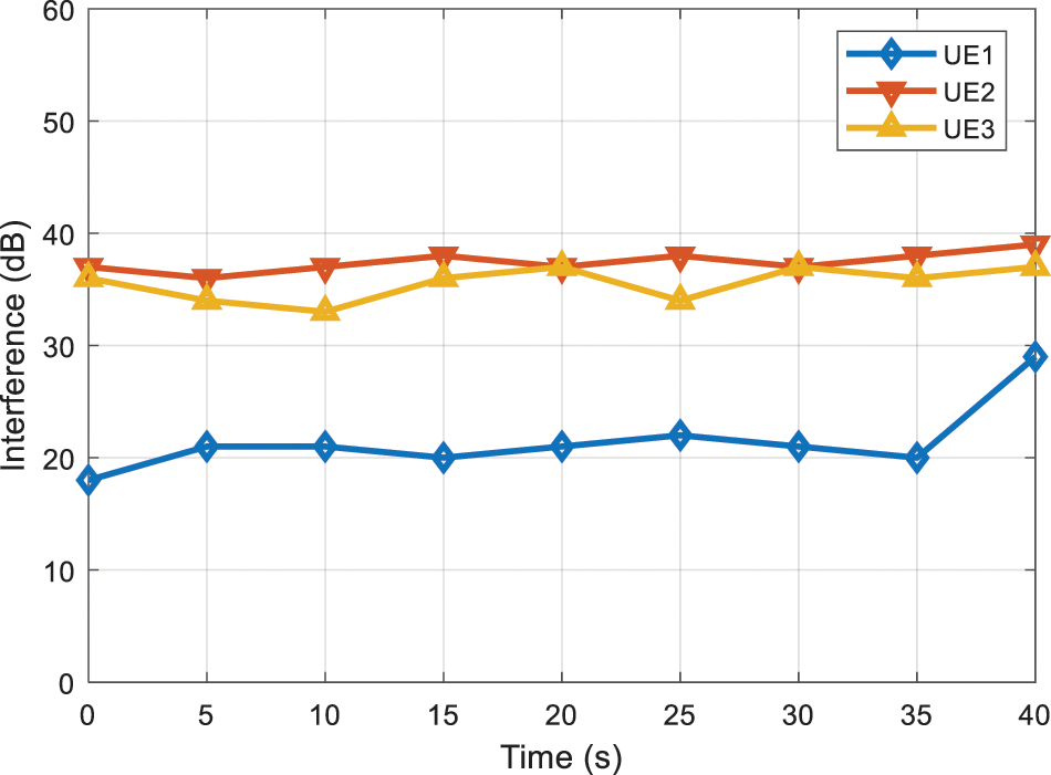
Figure 9: Simulation results of interference coordination for each link of the mmWaveB network
In Fig. 8, the SNR of the mmWaveA network’s undisturbed links UE1 and UE3 and the undisturbed links UE2 and UE3 in Fig. 9 have no significant change before and after the interference coordination is triggered by the SDN control layer coordinator. In Figs. 8 and 9, when the link where UE2 of the mmWaveA network is located and the link of UE3 of the mmWaveB network is severely interfered with by the same frequency, the SDN control layer coordination mechanism is triggered. The SDN controller acquires the interfering link users in different gNB networks and reallocates non-interfering spectrum resources to the inter-network interfering links of all networks, thus solving the problem of massive MIMO caused by the uncoordinated allocation of different beam spectrum resources. After adopting the SDN centralized management and scheduling scheme for interfering link resources, the interfering link between user UE2 of the mmWaveA network and UE3 in mmWaveB is reassigned resources, the mutual interference between links is significantly weakened, and the SNR of the interfering link is greatly improved, thereby improving the user’s communication quality. This helps to reduce the bit error rate (BER) of data transmission between gNB and UE and ultimately effectively improves the user’s communication quality in the system.
Fig. 10 compares the interference levels of the proposed algorithm with those of the reference [44,45] algorithms. As can be seen from Fig. 10, the interference level of reference [44] is lower than reference [45]. On the other hand, the interference level of the proposed algorithm is lower than both existing algorithms, which validates its effectiveness and robustness to dynamic channel scenarios.
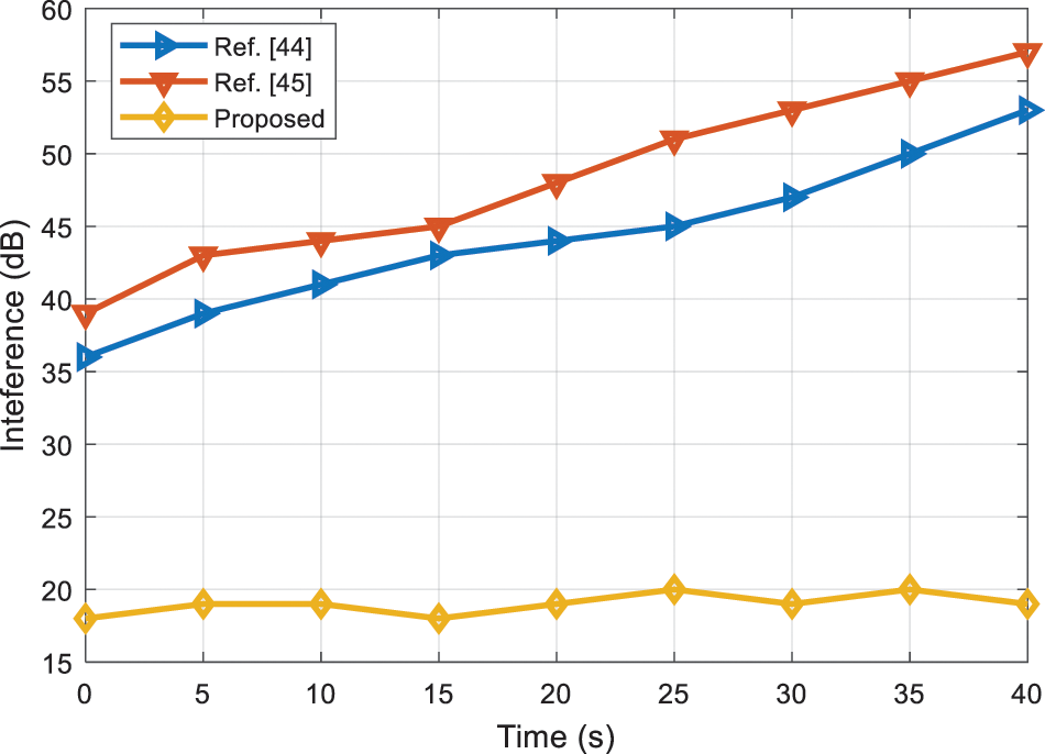
Figure 10: Performance comparison of the proposed and existing algorithms
This paper proposes massive MIMO technology and a centralized management method for SDN link resources. The inter-network interference link pair information is obtained via the SDN control layer’s centralized management scheme, and the inter-network interference link pair is deployed to build an interference graph and color the interference graph, allocate spectrum resources, and allocate mutually orthogonal spectrum to the inter-network interference link resources, which can effectively reduce inter-network user interference. Compared with the simple massive MIMO spectrum resource-sharing mechanism, the use of the SDN link coordination mechanism can solve the problem of inter-network link interference caused by the unreasonable allocation of spectrum resources in massive MIMO beams. With the combination of SDN and massive MIMO, the same-frequency interference of the link can be avoided, the average SNR of the link can be improved, and the communication quality of the user can be improved. The next step is to consider the energy efficiency of the system in different usage scenarios.
Acknowledgement: The authors would like to thank the editors and reviewers for their review and recommendations.
Funding Statement: The authors received no specific funding for this study.
Conflicts of Interest: The authors declare that they have no conflicts of interest to report regarding the present study.
References
1. T. Jabeen, Z. Ali, W. U. Khan, F. Jameel, I. Khan et al., “Joint power allocation and link selection for multi-carrier buffer aided relay network,” Electronics, vol. 8, no. 6, pp. 1–14, 2019. [Google Scholar]
2. K. Bakht, F. Jameel, Z. Ali, W. U. Khan, I. Khan et al., “Power allocation and user assignment scheme for beyond 5G heterogeneous networks,” Wireless Communications and Mobile Computing, vol. 7, pp. 1–9, 2019. [Google Scholar]
3. S. L. Mohammed, M. H. Alsharif, S. K. Gharghan, I. Khan and M. Albreem, “Robust hybrid beamforming scheme for millimeter-wave massive MIMO 5G wireless networks,” Symmetry, vol. 11, no. 11, pp. 1–16, 2019. [Google Scholar]
4. W. Shahjehan, A. Riaz, I. Khan, A. S. Sadiq, S. Khan et al., “Bat algorithm-based beamforming for mmwave massive mimo systems,” International Journal of Communication Systems, vol. 33, no. 2, pp. 845–904, 2020. [Google Scholar]
5. Q. Alsafasfeh, O. A. Saraereh, A. Ali, L. Al-Tarawneh, I. Khan et al., “Efficient power control framework for small-cell heterogeneous networks,” Sensors, vol. 20, no. 5, pp. 1–14, 2019. [Google Scholar]
6. R. M. Narayanan, R. K. Pooler, A. F. Martone, K. A. Gallagher and K. D. Sherbondy, “The spectrum analysis solution (SAS) system: Theoretical analysis, hardware design and implementation,” Sensors, vol. 18, no. 2, pp. 1–22, 2018. [Google Scholar]
7. K. Kotobi, P. B. Mainwaring, C. S. Tucker and S. G. Bilen, “Data-throughput enhancement using data mining-informed cognitive radio,” Electronics, vol. 4, no. 2, pp. 1–19, 2015. [Google Scholar]
8. S. Haykin, “Cognitive-radio: Brain-empowered wireless communications,” IEEE Journal on Selected Areas in Communications, vol. 23, no. 2, pp. 201–220, 2005. [Google Scholar]
9. A. Goldsmith, A. S. Jafar, I. Maric and S. Srinivasa, “Breaking spectrum gridlock with cognitive radios: An information theoretic perspective,” Proceedings of the IEEE, vol. 97, no. 5, pp. 894–914, 2009. [Google Scholar]
10. L. Zhang, Y. C. Liang and Y. Xin, “Joint beamforming and power allocation for multiple access channels in cognitive radio networks,” IEEE Journal on Selected Areas in Communications, vol. 26, no. 1, pp. 38–51, 2008. [Google Scholar]
11. G. Zhao, J. Ma, Y. Li, T. Wu, Y. H. Kwon et al., “Spatial spectrum holes for cognitive radio with directional transmission,” in IEEE Global Telecommunications Conf., New Orleans, USA, pp. 1–5, 2008. [Google Scholar]
12. T. Yoo and A. Goldsmith, “On the optimality of multiantenna broadcast scheduling using zero-forcing beamforming,” IEEE Journal on Selected Areas in Communications, vol. 24, no. 3, pp. 528–541, 2006. [Google Scholar]
13. M. Schubert and H. Boche, “Solution of the multiuser downlink beamforming problem with individual SINR constraints,” IEEE Transactions on Vehicular Technology, vol. 53, no. 1, pp. 18–28, 2004. [Google Scholar]
14. D. J. Costello, “Fundamentals of wireless communication,” IEEE Transactions on Information Theory, vol. 55, no. 2, pp. 919–920, 2009. [Google Scholar]
15. Z. H. Qaisar, M. Irfan, T. Ali, A. Ahmad, G. Ali et al., “Effective beamforming technique amid optimal value for wireless communication,” Electronics, vol. 9, no. 11, pp. 1–18, 2020. [Google Scholar]
16. M. Tareq, E. A. Sundarajan, M. Mohd and N. S. Sani, “Online clustering of evolving data streams using a density grid-based method,” IEEE Access, vol. 8, pp. 166472–166490, 2020. [Google Scholar]
17. A. Nasif, Z. A. Othman and N. S. Sani, “The deep learning solutions on lossless compression methods for alleviating data load on IoT nodes in smart cities,” Sensors Journal, vol. 21, no. 12, pp. 1–23, 2021. [Google Scholar]
18. A. S. Abdulameer, S. Tiun, N. S. Sani, M. Ayob and A. Taha, “Enhanced clustering models with wiki-based k-neared neighbors-based representation for web search result clustering,” Journal of King Saud University, vol. 8, no. 3, pp. 878–891, 2020. [Google Scholar]
19. W. Fook, A. Rahman, N. S. Sani and A. Adam, “Resource optimization using multithreading in support vector machine,” International Journal of Advanced Computer Science and Applications, vol. 11, no. 4, pp. 356–359, 2020. [Google Scholar]
20. G. M. Alathamneh, S. Abdullah and N. S. Sani, “Genetic algorithm selection strategies based rough set for attribute reduction,” International Journal of Computer Science and Network Security, vol. 19, no. 9, pp. 187–194, 2019. [Google Scholar]
21. Q. Yan, F. Yu and Q. Gong, “Software-defined networking (SDN) and distributed denial of service (DDoS) attacks in cloud computing environments: A survey, some research issues, and challenges,” IEEE Communication Surveys & Tutorials, vol. 18, no. 1, pp. 602–622, 2016. [Google Scholar]
22. X. An, J. Su and X. Lu, “Hypergraph clustering model-based association analysis of DDoS attacks in fog computing intrusion detection system,” EURASIP Journal on Wireless Communications and Networking, vol. 8, no. 4, pp. 1–15, 2018. [Google Scholar]
23. A. Ibrahim, K. Tarik and S. Konstantinos, “Network slicing and softwarization: A survey on principles, enabling technologies, and solutions,” IEEE Communications Surveys & Tutorials, vol. 20, no. 3, pp. 2429–2453, 2018. [Google Scholar]
24. G. Yan, “Simulation analysis of key technology optimization of 5G mobile communication network based on internet of things technology,” International Journal of Distributed Sensor Networks, vol. 15, no. 6, pp. 1–11, 2019. [Google Scholar]
25. Y. Zikria, S. Kim, M. Afzal, H. Wang and M. Rehmani, “5G mobile services and scenarios: Challenges and solutions,” Sustainability, vol. 10, no. 10, pp. 1–23, 2018. [Google Scholar]
26. V. Pana, O. Babalola and V. Balyan, “5G radio access networks: A survey,” Array Journal, vol. 14, no. 4, pp. 1–19, 2022. [Google Scholar]
27. N. Kumaratharan and P. Dananjayan, “Performance improvement in detection and estimation of MC-CDMA systems over MIMO channels,” Computers & Electrical Engineering, vol. 36, no. 1, pp. 224–233, 2010. [Google Scholar]
28. Y. Liu, X. Qin, Y. Huang, L. Tang and J. Fu, “Maximizing energy efficiency in hybrid overlay-underlay cognitive radio networks based on energy harvesting-cooperative spectrum sensing,” Energies Journal, vol. 15, no. 8, pp. 1–23, 2022. [Google Scholar]
29. S. Chiu, C. Lin and G. Lin, “Empowering device-to-device networks with cross-link interference management,” IEEE Transactions on Mobile Computing, vol. 16, no. 4, pp. 950–963, 2017. [Google Scholar]
30. H. Askari, N. Hussain, D. Choi, M. Sufian, A. Abbas et al., “An AMC-based circularly polarized antenna for 5G sub-6 GHz communications,” Computers, Materials & Continua, vol. 69, no. 3, pp. 2997–3013, 2021. [Google Scholar]
31. M. Sufia, N. Hussain, H. Askari, S. Park, K. Shin et al., “Isolation enhancement of a metasurface-based MIMO antenna using slots and shorting pins,” IEEE Access, vol. 9, pp. 73533–73543, 2021. [Google Scholar]
32. H. Askari, N. Hussain, M. Sufian, S. Lee and N. Kim, “A wideband circularly polarized magnetoelectric dipole antenna for 5G millimeter-wave communications,” Sensors, vol. 22, no. 6, pp. 1–18, 2022. [Google Scholar]
33. J. Caro, J. Ansari, J. Sachs, P. Bruin, S. Sivri et al., “Empirical study on 5G NR cochannel coexistence,” Electronics, vol. 11, no. 11, pp. 1–16, 2022. [Google Scholar]
34. Y. Kim, K. Youngbum, J. Oh, H. Ji, J. Yeo et al., “New radio (NR) and its evolution toward 5G-advanced,” IEEE Wireless Communications, vol. 26, no. 3, pp. 2–7, 2019. [Google Scholar]
35. Z. Bouida, A. Ghrayeb and K. Qaraqe, “Adaptive spatial modulation for spectrally-efficient MIMO systems,” in Proc. of the IEEE Int. Symp. on Personal, Indoor, and Mobile Radio Communication, Washington D.C, USA, pp. 583–587, 2015. [Google Scholar]
36. L. Wang, H. Ngo and M. Elkashlan, “Massive MIMO in spectrum sharing networks: Achievable rate and power efficiency,” IEEE Systems Journals, vol. 11, no. 1, pp. 20–31, 2017. [Google Scholar]
37. V. Sridhar, T. Gabillard and A. Manikas, “Spatiotemporal MIMO channel estimator and beamformer for 5G,” IEEE Transactions on Wireless Communications, vol. 15, no. 12, pp. 8025–8038, 2016. [Google Scholar]
38. H. Hie, B. Wang and F. Gao, “A full-space spectrum sharing strategy for massive MIMO cognitive radio systems,” IEEE Journal on Selected Areas in Communications, vol. 34, no. 10, pp. 2537–2549, 2016. [Google Scholar]
39. Y. Oktian, S. Lee, H. Lee and J. Lam, “Distributed SDN controller system: A survey on design choice,” Computer Networks, vol. 121, no. 3, pp. 100–111, 2017. [Google Scholar]
40. R. Alsharfa, S. Mohammed, S. Gharghan, I. Khan and B. J. Choi, “Cellular-D2D resource allocation algorithm based on user fairness,” Electronics Journal, vol. 9, no. 3, pp. 1–14, 2020. [Google Scholar]
41. L. Campanile, M. Gribaudo, M. Lacono, F. Marulli and M. Mastroianni, “Computer network simulation with NS-3: A systematic literature survey,” Electronics Journal, vol. 9, no. 2, pp. 1–23, 2020. [Google Scholar]
42. D. Baranov, A. Terekhin, D. Bragin and A. Konev, “Implementation and evaluation of nodal distribution and movement in a 5G mobile network,” Future Internet, vol. 13, no. 12, pp. 1–17, 2021. [Google Scholar]
43. A. Musa and I. Awan, “Functional and performance analysis of discrete event network simulation tools,” Simulation Modelling Practice and Theory, vol. 116, no. 5, pp. 1024–1035, 2022. [Google Scholar]
44. D. Siafarikas, E. Alwan and J. Volakis, “Interference mitigation for 5G millimeter-wave communications,” IEEE Access, vol. 7, pp. 7448–7455, 2018. [Google Scholar]
45. W. Lim, G. Kwon and H. Park, “Interference mitigation using random antenna selection in millimeter wave beamforming,” EURASIP Journal on Wireless Communications and Networking, vol. 87, no. 1, pp. 1–16, 2017. [Google Scholar]
Cite This Article
 Copyright © 2023 The Author(s). Published by Tech Science Press.
This work is licensed under a Creative Commons Attribution 4.0 International License , which permits unrestricted use, distribution, and reproduction in any medium, provided the original work is properly cited.
 Downloads
 Citation Tools