
 Submit a Paper
 Propose a Special lssue
 Open Access
ARTICLE

Defected Ground Structure Multiple Input-Output Antenna For Wireless Applications
1 Department of Electronics and Communication Engineering, RF Microwave & Wireless Communication Laboratory, Hindusthan Institute of Technology, Coimbatore, 641028, Tamil Nadu, India
2 Department of Electronics and Communication Engineering, Hindusthan College of Engineering & Technology, Coimbatore, 641050, Tamil Nadu, India
* Corresponding Author: Ramya Sridhar. Email:
Computer Systems Science and Engineering 2023, 46(2), 2109-2122. https://doi.org/10.32604/csse.2023.036781
Received 12 October 2022; Accepted 08 December 2022; Issue published 09 February 2023
 View Full Text
 Download PDF
Abstract
In this paper, the investigation of a novel compact 2 × 2, 2 × 1, and 1 × 1 Ultra-Wide Band (UWB) based Multiple-Input Multiple-Output (MIMO) antenna with Defected Ground Structure (DGS) is employed. The proposed Electromagnetic Radiation Structures (ERS) is composed of multiple radiating elements. These MIMO antennas are designed and analyzed with and without DGS. The feeding is introduced by a microstrip-fed line to significantly moderate the radiating structure’s overall size, which is 60 × 40 × 1 mm. The high directivity and divergence characteristics are attained by introducing the microstrip-fed lines perpendicular to each other. And the projected MIMO antenna structures are compared with others by using parameters like Return Loss (RL), Voltage Standing Wave Ratio (VSWR), Radiation Pattern (RP), radiation efficiency, and directivity. The same MIMO set-up is redesigned with DGS, and the resultant parameters are compared. Finally, the Multiple Input and Multiple Output Radiating Structures with and without DGS are compared for result considerations like RL, VSWR, RP, radiation efficiency, and directivity. This projected antenna displays an omnidirectional RP with moderate gain, which is highly recommended for human healthcare applications. By introducing the defected ground structure in bottom layer the lower cut-off frequencies of 2.3, 4.5 and 6.0 GHz are achieved with few biological effects on radio propagation in human body communications. The proposed design covers numerous well-known wireless standards, along with dual-function DGS slots, and it can be easily integrated into Wireless Body Area Networks (WBAN) in medical applications. This WBAN links the autonomous nodes that may be situated either in the clothes, on-body or beneath the skin of a person. This system typically advances the complete human body and the inter-connected nodes through a wireless communication channel.Keywords
In wireless communication, smart antenna systems have garnered interest due to their ability to dramatically increase data throughput and link range without increasing bandwidth requirements [1]. Multiple-Input Multiple-Output (MIMO) antennas promise a cost-effective way to provide high data rates, better Quality of Service (QoS), frequency radio spectrum, and multipath services. The longer pulse shape is imposed by activating MIMO, and the single-aid Radio Frequency (RF) along with multiple antennae transmitting structure is implemented. A meander strip and inverted L-strip antennas are isolated by an inter-digital Split Ring Resonator (SRR) to improve the isolation characteristics over the Long Term Evolution (LTE) band. Author [2] modifies the E-shape patch antenna for MIMO systems. This modified antenna achieves improved directivity, gain, Return Loss (RL) and VSWR characteristics compared to a Single Input and Single Output (SISU) system. Different feed structures [3], such as series feed, corporate feed, and corporate-series feed array, are adopted for different RS, like 4 × 1, 4 × 2, and 4 × 3. This cooperative MIMO and feeding structure produces enriched directivity and efficiency along with good beam structure. The author [4] designed a tiny micro-strip radiating patch to take advantage of the advantages of polarization. This simple elliptical radiating antenna reaches 5 GHz for Wi-Fi network applications. A 2 × 2 MIMO system operates 2.4 GHz for medical, industrial, and scientific applications. The above antenna is a very compact microstrip patch with double-side printing fed by a microstrip line. The author [5] compares the antenna parameters like directivity, RL, VSWR, and gain of the MIMO-based radiating structure along with the Electromagnetic Band-Gap (EBG) structure and without the EBG structure.
In this paper [6], the model analysis is carried out for metallic ring structures in order to achieve an orthogonal radiating structure. Along with this geometry, different feeding structures are adopted, and their results are compared for the MIMO model. The low-profile MIMO-based inverted F-RS achieves 3.4 and 5.9 GHz, respectively. This modified monopole structure supports an omnidirectional RP for LTE applications. The compact-size MIMO antennas are designed using meta-materials, and the antenna performance characteristics have been improved. Therefore, as the size decreases, the antenna performance increases, as measured and proved significantly by the author [7]. Deals with electromagnetic isolation characteristics between two antennas used in the MIMO system were analyzed mathematically [8]. By adopting DGS in MIMO technologies, the mutual coupling between the antennas is observed [9]. In this way, the performance characteristics of the MIMO antenna are also improved by using the closely packed structure of the radiating pattern.
This article bounces with enhanced medical applications like early cancer detection and related disease detection by using this MIMO antenna for Wireless Body Area Networks (WBAN) via in-body and on-body communications. This antenna structure ensures low power consumption as it is used directly in the patient’s body, interoperability for a link, and intercommunication in a synchronized method. These advances are working in the medical field by introducing MIMO technology (design and analysis) for UWB-WBAN applications (wearable devices) like in-body and on-body communications. This technology plays a vital role in advancing medical treatment at an affordable cost.
The summary of this research paper and its involvement in science is listed below:
1. MIMO, DGS, UWB, WBAN, RL, and VSWR are used for designing the WBSN medical diagnosis system.
2. The designing structures are applied with 2 × 2, 2 × 1 and 1 × 1 antennas, and their results are analyzed and compared with the identical MIMO pattern antennas with DGS.
3. The compact structure with UWB and WBAN frequencies is completed with good radiation efficiency.
4. Enhanced medical applications like early cancer detection and related disease detection can be achieved by using WBAN via in-body and on-body communications.
5. This antenna structure ensures low energy consumption as it is used directly in the patient’s body, provides interoperability for a link, and intercommunicates in a synchronized method.
The rest of this article is organized as follows: Section 2 deals with a literature review for design parameter analysis and radiation factor investigation. In Section 3, antenna designs like 2 × 2, 2 × 1 and 1 × 1 are presented with a plane ground structure and DGS. Section 4 results for MIMO antennas are discussed with and without DGS. These results are compared between their constructions of 2 × 2, 2 × 1 and 1 × 1. Again, these results (RL and VSWR) are compared with standard ground structure and DGS. Finally, Section 5 concludes that a 2 × 1 MIMO antenna with DGS has decent RL, High Gain (HG) and directivity characteristics.
A novel bending of RS is embraced to showcase the electromagnetic effect on the human hand and head. In addition, the DGS is combined with a compact RS to provide improved radiation efficiency. Extensive ERS is reduced by using the capacity limits in MIMO technology, and the same is achieved by proper geometrical selection of the feeding slot in a RS. This letter suggests that the different feeding positions and their dimensions avoid SNR in MIMO technology. Moreover, a conventional capacity method is carried out to improve the wideband characteristics. Author [10], the Minimum Mean Square Error (MMSE) technique, along with the optimum combiner, was implemented to reduce the bit error rate in the receiver. Therefore, the performance of the multiple-antenna system was improved, which increased the channel capacity. In this proposed method, good isolation characteristics were achieved by arranging the 4-element array perpendicular to each other. By putting a bent slit in each radiating patch, the frequency range can be made wider.
A 3D integral numerical method is adopted by the author [11] to analyze and maximize the presence of output SNR. The novel combiner gives a more hopeful approximation of the performance than the actual performance with the usual BER. Essentially, each transmits (or receives) antenna gets paired individually, increasing the degrees of freedom for wireless communications. Moreover, the MIMO antenna helps with HG and is a good trade-off between electromagnetic waves. The author [12] considers multiple antennas with (i.e.) Rayleigh fading distribution, which is designed by nested lattice coding for high channel capacity and good SNR. In addition, this design produces improved multiplexing gain and diversity by using MMSE estimation. Due to the parallel connection between the transmitting and receiving antenna, supported by spatial multiplexing, a high data rate is possible.
In addition to this limit, the degree of freedom can increase channel capacity, supporting a high SNR regime. The author [13] suggests a traditional method to switch between diversity gain and spatial multiplexing gain instead of focusing on the design configuration to achieve either gain. The orthogonal fading for channel estimation adds additional support to this design goal with a nominal Bond Equivalent Yield (BER) [14]. Traditionally, an inverted F-structure is implemented with a constant dielectric substrate to incorporate the space-limited RF signals. Therefore, easy integration is carried out for RF modules with zero propagation in the primary operating mode [15]. The 802.11 n standards use 2.4 to 5.8 GHz, which is widely used in medical fields due to its increased data rate. The standard used in MIMO technology was that the two antennas were independent of each other and obtained uncorrelated waveforms. A low-profile UWB antenna structure supports WBAN applications [16–20]. The power handling capacity and ultra-wideband characteristics of MIMO antennas are further improved by adding DGS [21–23]. The two-radiating MIMO structure is stretched to an imposing four-element MIMO radiating structure by folding the arrays towards the antenna front side [24–25].
Furthermore, the authors [26–28] hardly delivered a methodical method for isolation enhancement in a compacted measurement and scalability context [29–30]. With the help of a modified rectangular slot and DGS in-ground part, the WBAN application characteristic is achieved. The bandwidth is from 3 to 10 GHz, and the VSWR is less than two for the resonant frequencies of 3.1, 5.1, 8, and 8.8 GHz. So, in MIMO antennas, the short circuit is seen on the top and bottom, and the open circuit is seen on the wall side to produce significant radiation (Table 1).
3.1 Projected Radiating Element Designs
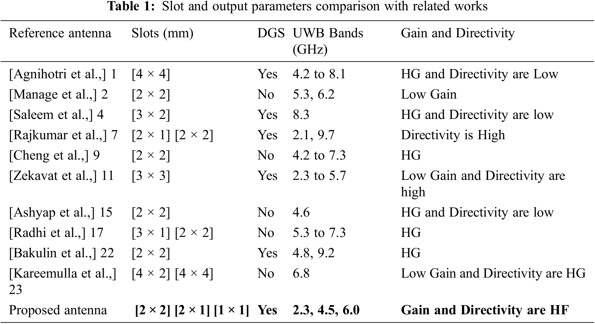
In order to attain the radiation features desired for on-body and off-body communication, the RS is designed as shown in Figs. 1a, 2a, and 3a. The antenna element has a symmetric radiating configuration with an untying edge on a Flame Retardant 4 (FR4) substrate with a relative permittivity of 4.4 and a loss tangent value of 0.02. Detailed dimensions of 2 × 2, 2 × 1 and 1 × 1 antennas are illustrated in Figs. 1b, 2b, and 3b. Each antenna consists of a capacitive feed of 50 Ω microstrip feedline. Fig. 1a shows the detailed geometry of a 2 × 2 RS with 110 × 40 × 2 mm3 and the RS of 20 × 7 mm2 rectangular shape connected with a circularized rectangle of 22 mm with a cut slot of 11 mm × 5 mm in each RS and a 15 mm gap between the symmetrical RS. By putting the feed line near the connecting lines, which acts as a band-stop filter, the isolation is made better.
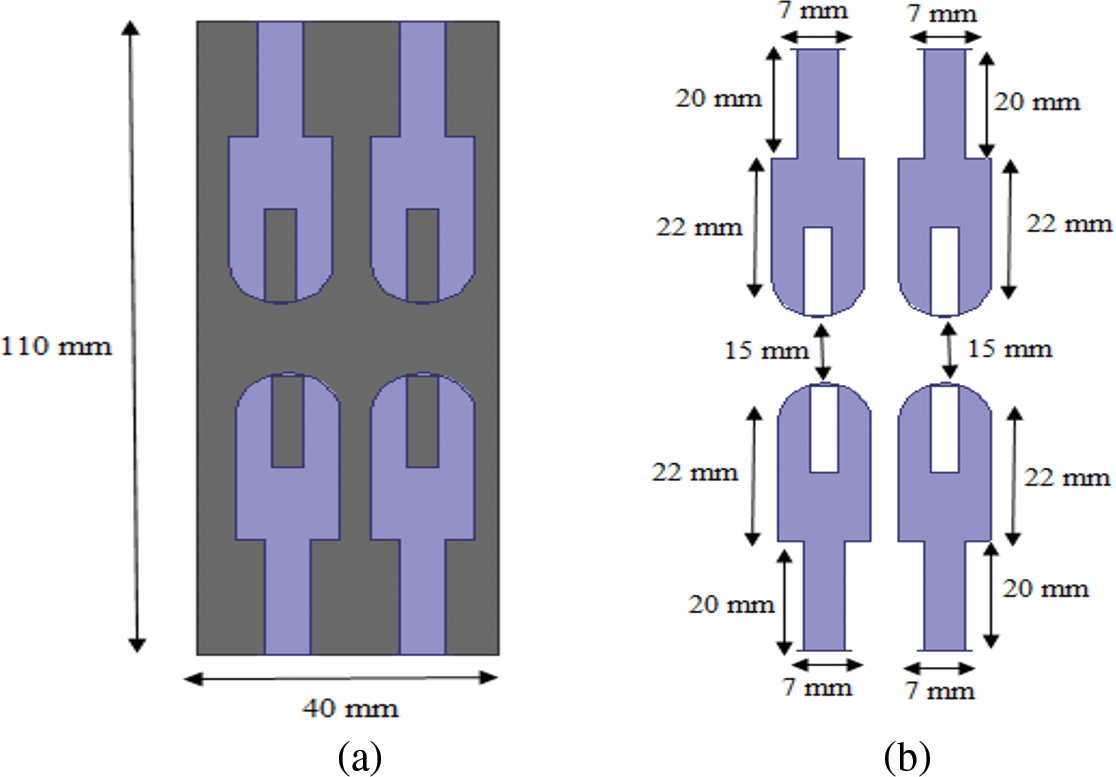
Figure 1: (a) Geometry of 2 × 2 MIMO antenna (b) Geometry of 2 × 2 MIMO-RS
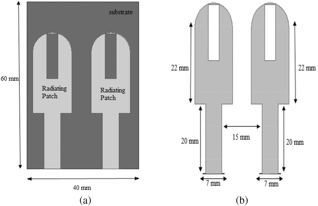
Figure 2: (a) The geometry of 2 × 1 MIMO antenna (b) RS of 2 × 1 MIMO antenna
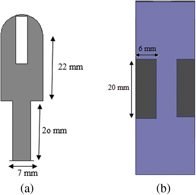
Figure 3: (a) The geometry of 1 × 1 MIMO antenna (b) RS of 1 × 1 MIMO antenna
Fig. 2a illustrates the overall geometry of a 2 × 1 MIMO antenna with 60 × 40 × 2 mm3 with the RS of a 20 × 7 mm rectangle along with 22 mm of a circularized rectangle with a cut slot of 11 × 5 mm in both RS. The antenna possesses a 15-mm gap between the symmetrical RS. A similar way of polarizing the RS achieves an excellent isolation characteristic. Fig. 3a illustrates the geometry of radiating patch along with the substrate of 60 × 20 × 2 mm, and the geometry of the RS is a 20 × 7 mm rectangular shape attached to a 22 mm circularized rectangle with a cut slot of 11 × 5 mm.
3.2 Defected Ground Structures
Exemplified geometry of 1 × 1, 2 × 1 and 2 × 2 structures is designed by using these basic formulas by using Frequency Operation (FO) = 6 GHz and the dielectric constant for the substrate, εr = 2.2.
The DGS of the 2 × 2 MIMO antenna is demonstrated in Fig. 4a. The defect etched in the ground plane of the RS gives amplification to the cumulative effective capacitance ‘C’ and inductance ‘L’. The Fig. 4b gives the complete information of the DGS of the 2 × 1 slot MIMO antenna with the security parameters a1=20 mm, a2=m, b1=10 mm, b2=3.5 mm, b3=3.5 mm, b4=2.5 mm and b5=4 mm This proposed DGS has some advantages, like (i) a high slow wave factor and a more compact structure. (ii) A narrow-width stop band and in-depth rejection. (iii) Larger transfer characteristics.
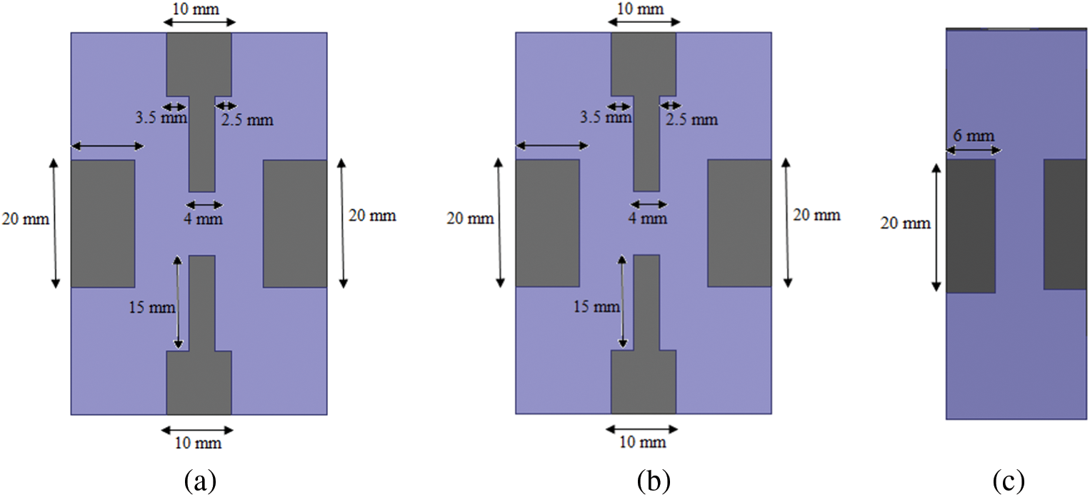
Figure 4: (a) DGS of 2 × 2 slot MIMO antenna (b) DGS of 2 × 1 slot MIMO antenna (c) DGS of 1 × 1 antenna
The DGS of the 1 × 1 UWB antenna is shown in Fig. 4c with the fixed parameters of a1 = 20 and a2 = 6 mm in a rectangle shape for both sides of the DGS. This DGS generates a disturbance in the current distribution, presenting the inductance and capacitance characteristics of the transmission line. As shown in Fig. 4a–4c, the suitable dielectric material is selected for the MIMO antenna in order to enrich the adequate bandwidth, gain and diminish the mutual coupling among two grids. Besides suppressing the higher-order harmonics, undesirable cross-polarization produces bumpy bands to halt interference with other bands. Several applications of DGS are analyzed with fixed sequential and non-sequential cascaded configuration methods, which affect the ground of a transmission plane. It also disturbs the protected current dissemination in the ground plane; therefore, this disturbance will cause changes in the characteristics of a transmission line. The DGS possess filtering characteristics, which are applied to MIMO antennas significantly to reduce the mutual coupling between electromagnetic waves and unwanted responses. A more compact structure with less RL is the main advantage of the DGS structure. The length and width of the ground plane are calculated using Eqs. (1) and (2).
Where, I represents 6 (6 sides of antenna), hs is the height of the substrate. (Ldg, Wdg) are the length and width of the DGS, respectively. The operative length of radiating structure is identical to partial of a wave length inside the dielectric standard. Since ‘L’ represents the function of operative dielectric constant and the thickness with height ratio. Wg is stately in horizontal (or) vertical surface and it is also the space between the two arguments and the power is much smaller than half of the maximum. Based on the width and length equations, different DGS have been implemented for different slot antennas. DGS possesses unique discrete features depending on the design and geometry; therefore, it filters out the annoying signals and tunes up the higher-order signals without increasing the circuit complexity. The different ground geometry and DGS are adopted for 1 × 1, 2 × 1 and 2 × 2 slots, but the bandwidth for all the slots is more or less the same with improved RL. The voltage standing wave ratio characteristics are less than two, and gain is analyzed for all antennas with DGS, in which the 2 × 1 MIMO antenna achieves more gain when compared to other slots of antennas.
The RL and VSWR characteristics of the proposed 2 × 2 MIMO antenna system with and without DGS are shown in Figs. 5a and 5b. The measured 10-dB impedance bandwidth of the MIMO antenna with DGS arises from 2.5 to 7 GHz to attain the enhanced UWB characteristics. When the ratio of the peak amplitude of a standing wave to the minimum amplitude of a standing wave is less than 2, the VSWR is less than 2.
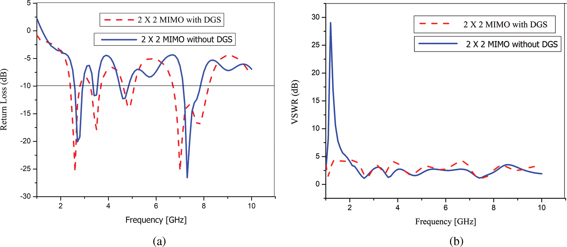
Figure 5: (a) RL comparison of 2 × 2 slot antenna with and without DGS (b) VSWR comparison of 2 × 2 antenna slot antenna with and without DGS
Figs. 6a and 6b represent the comparison in RL characteristics and VSWR characteristics of the proposed 1 × 2 MIMO antenna system with and without DGS. The 1 × 2 MIMO antenna with DGS produces the multi-band resonance frequencies at 2.3, 4.5 and 6.0 GHz. The measured −10 dB impedance bandwidth varies from 2.2 to 6.2 GHz in order to achieve enhanced UWB characteristics. The maximum to the minimum voltage on a lossless line is achieved at less than 2 for DGS and without DGS systems.
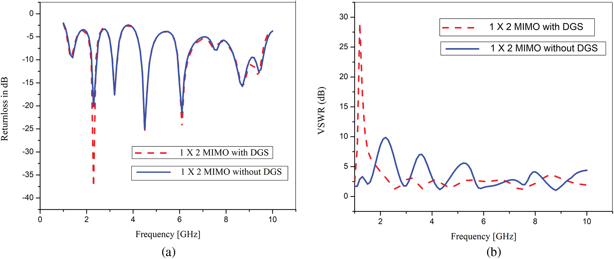
Figure 6: (a) RL comparison of 1 × 2 antenna with and without DGS (b) VSWR comparison of 1 × 2 without DGS antenna with and without DGS
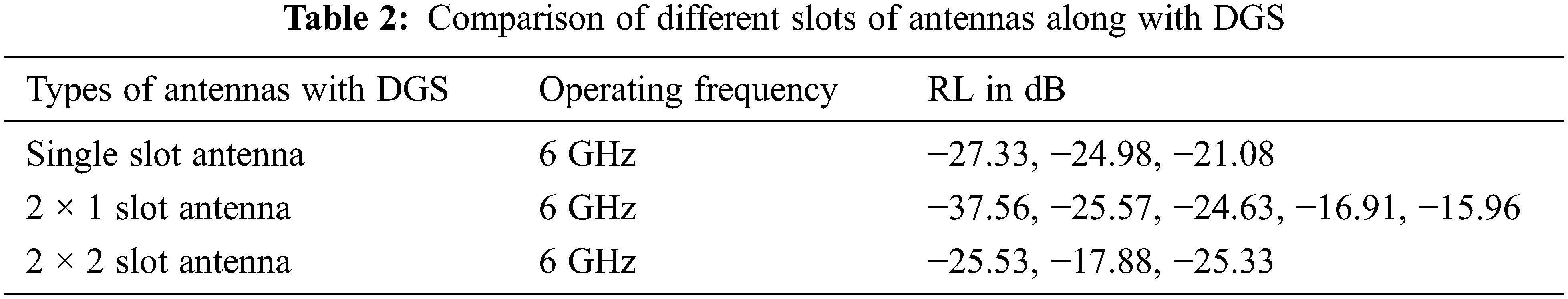
Fig. 7a compares the RL of 1 × 1 RS with and without DGS. Whereas the radiating slot without DGS exhibits a single bandwidth at 3 GHz when DGS is introduced to the same radiating element, it displays three bandwidths at 2.5, 3, 4.5 GHz for improved RL at −27.33, −24.98, and −21.08 dB. The comparison between the VSWR characteristics with and without DGS of the 1 × 1 antenna is shown in Fig. 7b. The single-slot antenna with DGS achieves VSWR characteristics of less than 2. The ERS exhibits single bandwidth characteristics without DGS and achieves three bandwidth characteristics less than 5 GHz for the same RS with DGS. Therefore, this 1 × 1 ERS retains more accurate structures with the periodic organization of dielectric or attractive ingredients that result in the creation of stop bands in the microwave frequency called microwave band gap structures. The electromagnetic influences wandering throughout the structures familiarize an episodic difference of dielectric permittivity (or magnetic permeability) parallel to the potential energy of an electron.
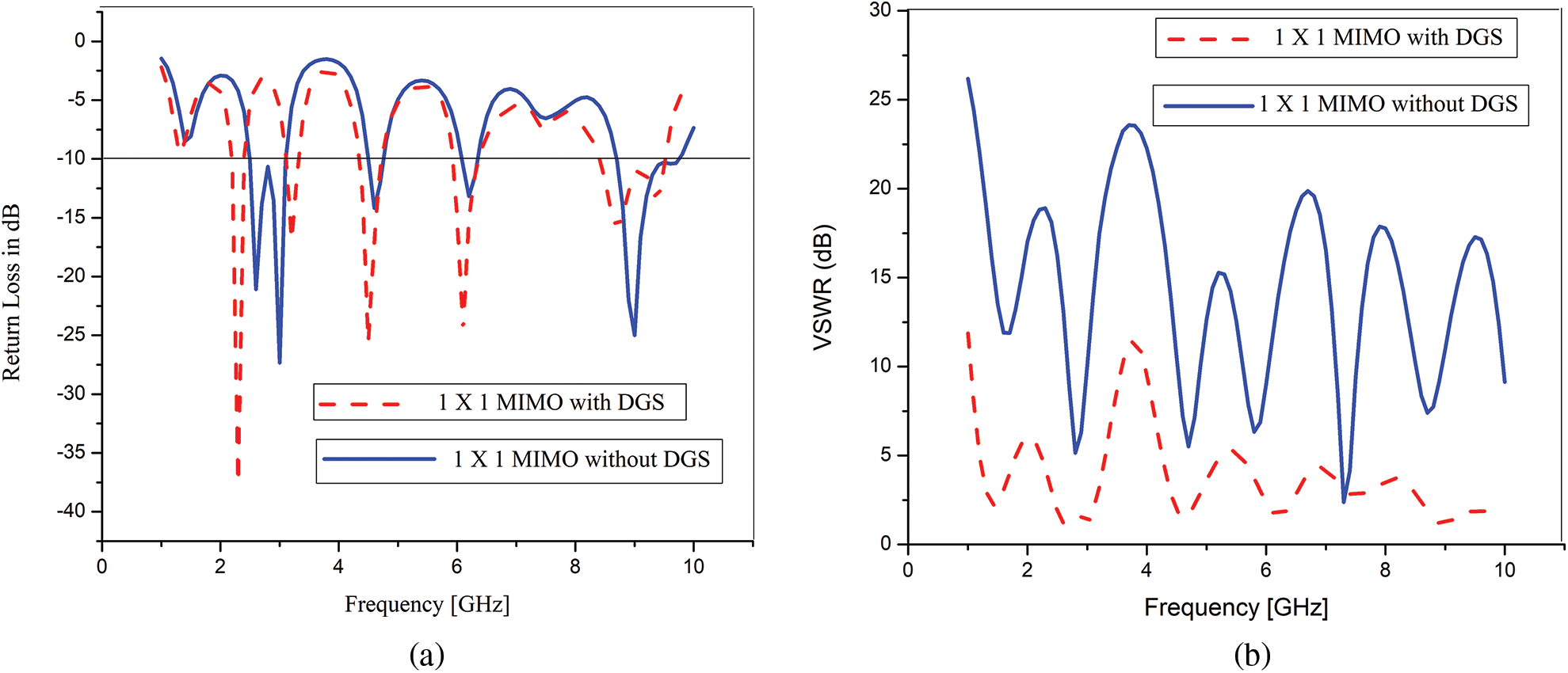
Figure 7: (a) RL comparison of a single antenna with and without a DGS (b) VSWR comparison of single antenna with and with without DGS
The transferred radio frequency wave on a finite transmission line for maximum power transfer from source to load is equal to the load’s impedance and was verified using the Smith chart in Fig. 8 at frequencies ranging from 2.2 to 6.1 GHz. The RP of the 1 × 2 RS is obtained when ports are excited by a 50 Ω load. The DGS permits the current flow from the patch to the ground line, and the same effect is observed for other ports. Thus, the antenna displays stable radiation across the required operational band. Fig. 9 shows the simulated result of the 1 × 2 RS, and variation is observed around 4 dB around the RS with DGS.

Figure 8: Smith chart of 1 × 2 slot antenna
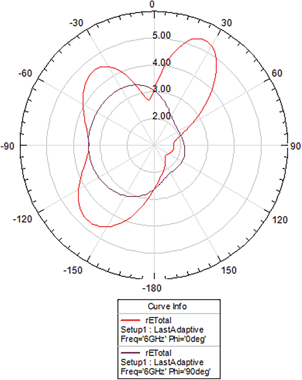
Figure 9: RP of 1 × 2 slot antenna
The RL and VSWR comparisons of single slot, 1 × 2; 2 × 2 slot RS with and without DGS are shown in Fig. 10a and 10b, and Fig. 11a and 11b. It clearly states different slot antennas with different color lines at the operating frequency of 6 GHz and the VSWR characteristics of less than 2.
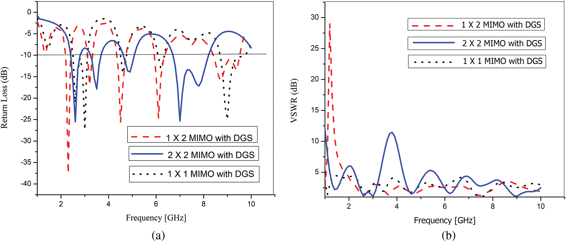
Figure 10: (a) RL comparison of single 1 × 2, 2 × 2 slot antennas with DGS (b) VSWR comparison of single 1 × 2 and 2 × 2 slot antennas with DGS
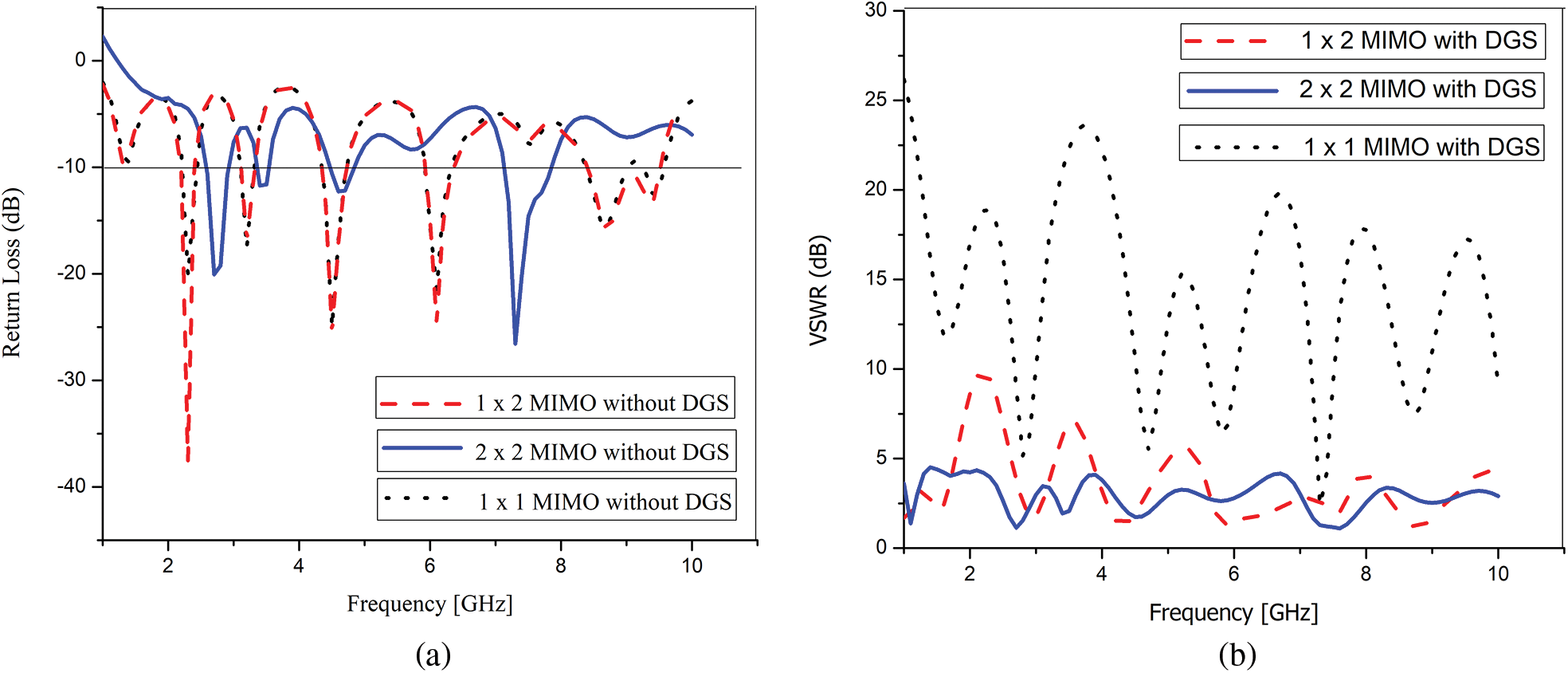
Figure 11: (a) RL comparison of single 1 × 2 and 2 × 2 slot antennas without DGS (b) VSWR comparison of single 1 × 2 and 2 × 2 slot antennas without DGS
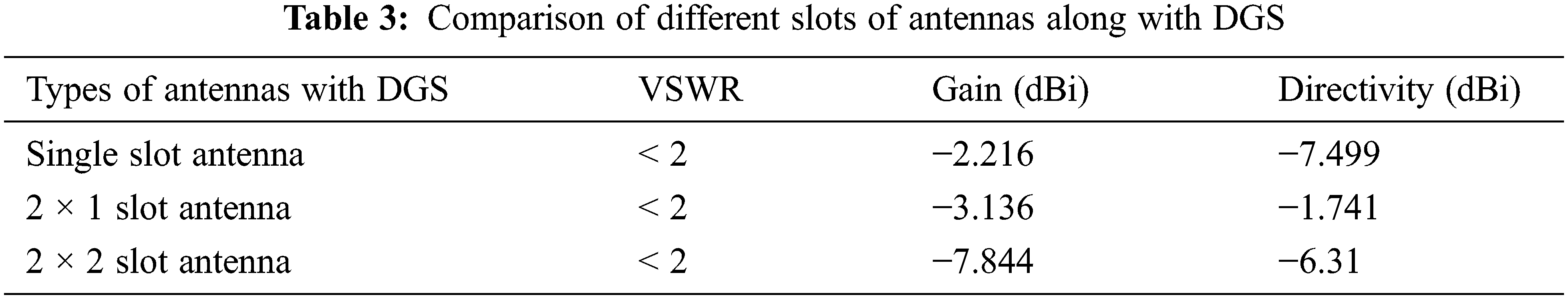
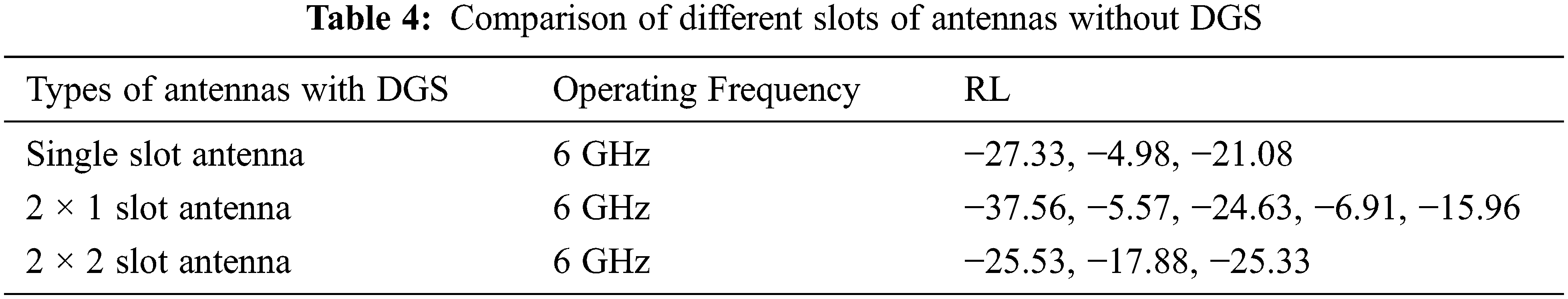
The above Tables 2 and 3 represent different slot antennas, with a DGS having a RL above 16 and a VSWR less than 2. It is observed that the 2 × 1 slot antenna attains maximum RL at −37.56 and −3.136 dBi gain with NAD −1.741 dBi directivity. The maximum RL of −2.89 is realized in a 2 × 1 ERS, which is clearly expressed in Tables 4 and 5, along with the different slot comparisons without DGS tabulated. The output frequency ranges from 2.3 to 6.0 with added features of accurateness and low power ingesting of our UWB-MIMO design sorts it as potential and operative choice for an assortment of medical applications. As UWB radio waves can enter human tissues deprived of any side effects, UWB wireless communication (WBAN) is a harmless alternative to medical imaging system at the same time as attaining accurate in-body communications of patients.

This paper compares different RS with and without DGS, and their performances are tabulated. 2 × 1 ERS with DGS has good RL, gain, and directivity characteristics compared to other non-DGS structures. It was evident from the output that integrating DGS made good progress in the bandwidth. The proposed design covers numerous well-known wireless standards, along with dual-function DGS slots, and it can be easily integrated into WBAN in medical applications.
The design’s future scope embraces UWB-MIMO technology implemented for narrow-band amenities to ignore possible interferences with adjacent communication frequencies. Subsequently, our MIMO-UWB adores a wide band and co-exists with additional applications. Also, a combination of these two technologies is investigated for accelerated speed in in-body and on-body communications. Research can be completed to increase the value of the small UWB-MIMO antennas with extensive impedance bandwidth.
Funding Statement: The authors received no specific funding for this study.
Conflicts of Interest: The authors declare that they have no conflicts of interest to report regarding the present study.
References
1. N. Agnihotri, A. Kantemur, J. Tak and H. Xin, “A reconfigurable UWB MIMO antenna for indoor and outdoor communication applications,” in Proc. of IEEE Int. Symp. on Antennas and Propagation and USNC-URSI Radio Science Meeting, Atlanta, GA, USA, pp. 2039–2040, 2019. [Google Scholar]
2. P. S. Manage, U. Naik, S. Kareemulla and V. Rayar, “Dual band-notched UWB-MIMO antenna incorporating CSRR for WLAN and X-band applications,” in Proc. of 3rd Int. Conf. on Smart Systems and Inventive Technology, Tirunelveli, India, pp. 149–152, 2020. [Google Scholar]
3. K. Muzaffar and M. I. Magray, “Compact four-element dual band-notched orthogonally placed UWB antennas for wireless MIMO applications,” in Proc. of APS Topical Conf. on Antennas and Propagation in Wireless Communications, Granada, Spain, pp. 285–287, 2019. [Google Scholar]
4. S. Saleem, S. Kumari, D. Yadav and D. Bhatnagar, “A high isolation UWB-MIMO antenna with dual-band rejection property,” in Proc. of IEEE Int. Conf. on Computing, Power and Communication Technologies, Greater Noida, India, pp. 212–216, 2020. [Google Scholar]
5. G. Abhik and G. Rowdra, “Utilization of shorted fractal resonator topology for high isolation and ELC resonator for band suppression in compact MIMO UWB antenna,” AEU-International Journal of Electronics and Communications, vol. 113, pp. 152978, 2020. [Google Scholar]
6. Z. Tang, X. Wu, J. Zhan, S. Hu et al., “Compact UWB-MIMO antenna with high isolation and triple band-notched characteristics,” IEEE Access, vol. 7, pp. 19856–19865, 2019. [Google Scholar]
7. S. Rajkumar, A. A. Amala and K. T. Selvan, “Isolation improvement of UWB MIMO antenna utilizing molecule fractal structure,” Electronics Letters, vol. 55, no. 10, pp. 576–579, 2019. [Google Scholar]
8. S. Singhal, “Feather-shaped super wideband MIMO antenna,” International Journal of Microwave and Wireless Technologies, vol. 13, no. 1, pp. 94–102, 2021. [Google Scholar]
9. Q. Cheng, Y. Liu, H. Zhang and Y. Hao, “A generic spiral MIMO array design method for short-range UWB imaging,” IEEE Antennas and Wireless Propagation Letters, vol. 19, no. 5, pp. 851–855, 2020. [Google Scholar]
10. S. Basir, K. S. Alimgeer, S. A. Ghauri, M. Maqsood, M. Sarfraz et al., “MIMO antenna with notches for UWB system,” International Journal of Antennas and Propagation, vol. 2022, pp. 1–8, 2022. [Google Scholar]
11. S. Zekavat, F. Afghah, R. Askari, J. Delabrouille, N. French et al., “Electromagnetic spectrum contribution in astronomy, health, atmospheric, geology and environment applications,” International Journal of Wireless Information Networks, vol. 29, no. 3, pp. 281–302, 2022. [Google Scholar]
12. J. Banerjee, A. Gorai and R. Ghatak, “Design and analysis of a compact UWB MIMO antenna incorporating fractal inspired isolation improvement and band rejection structures,” AEU-International Journal of Electronics and Communications, vol. 122, no. 11, pp. 153274, 2020. [Google Scholar]
13. R. A. Pandhare, M. P. Abegaonkar and C. Dhote, “UWB antenna with novel FSS reflector for the enhancement of the gain and bandwidth,” International Journal of Microwave and Wireless Technologies, vol. 16, no. 10, pp. 1353–1368, 2022. [Google Scholar]
14. T. Ali, M. S. Aw and R. C. Biradar, “A fractal quad-band antenna loaded with L-shaped slot and metamaterial for wireless application,” International Journal of Microwave and Wireless Technologies, vol. 10, no. 7, pp. 826–834, 2018. [Google Scholar]
15. A. Y. Ashyap, S. H. Dahlan, Z. Z. Abidin, M. R. Kamarudin, H. A. Majid et al., “C-shaped antenna based artificial magnetic conductor structure for wearable IoT healthcare devices,” Wireless Networks, vol. 27, no. 7, pp. 4967–4985, 2021. [Google Scholar]
16. L. R. Chandel, A. K. Gautam and K. Rambabu, “Tapered fed compact UWB MIMO-diversity antenna with dual band-notched characteristics,” IEEE Transactions on Antennas and Propagation, vol. 66, no. 4, pp. 1677–1684, 2018. [Google Scholar]
17. A. H. Radhi, R. Nilavalan, Y. Wang, H. S. A. Raweshidy, A. A. Eltokhy et al., “Mutual coupling reduction with a wideband planar decoupling structure for UWB-MIMO antennas,” International Journal of Microwave and Wireless Technologies, vol. 10, no. 10, pp. 1143–1154, 2018. [Google Scholar]
18. W. P. Nwadiugwu and D. S. Kim, “Novel MIMO-UWB-based AG-UG-AG routing with micro-bit sensors for WUSN,” IEEE Sensors Letters, vol. 5, no. 3, pp. 1–4, 2021. [Google Scholar]
19. M. Farahani and S. M. A. Nezhad, “A novel UWB printed monopole MIMO antenna with non-uniform transmission line using nonlinear model predictive,” Engineering Science and Technology, an International Journal, vol. 23, no. 6, pp. 1385–1396, 2020. [Google Scholar]
20. S. Modak and T. Khan, “A slotted UWB-MIMO antenna with quadruple band-notch characteristics using mushroom EBG structure,” AEU-International Journal of Electronics and Communications, vol. 134, no. 2, pp. 153673, 2021. [Google Scholar]
21. M. Wang, J. Nan and J. Liu, “High-isolation UWB-MIMO antenna with multiple X-shaped stubs loaded between ground planes,” International Journal of Antennas and Propagation, vol. 2021, no. 12, pp. 1–13, 2021. [Google Scholar]
22. M. G. Bakulin, V. B. Kreyndelin, D. Y. Pankratov and A. G. Stepanova, “Iterative massive MIMO demodulation method with non-gaussian approximation,” Journal of Communications Technology and Electronics, vol. 67, no. 6, pp. 740–746, 2022. [Google Scholar]
23. S. Kareemulla and V. Kumar, “Compact MIMO-antenna with enhanced isolation for ultra-wide-band and Ku-band applications,” Journal of Communications Technology and Electronics, vol. 67, no. 1, pp. 56–62, 2022. [Google Scholar]
24. M. Agarwal, J. K. Dhanoa and M. K. Khandelwal, “Two-port hexagon shaped MIMO microstrip antenna for UWB applications integrated with double stop bands for Wi-Max and WLAN,” AEU-International Journal of Electronics and Communications, vol. 138, no. 153885, pp. 1–15, 2021. [Google Scholar]
25. T. Govindan, S. K. Palaniswamy, M. Kanagasabai, S. Kumar, T. R. Rao et al., “Conformal quad-port UWB MIMO antenna for body-worn applications,” International Journal of Antennas and Propagation, vol. 2021, no. 4, pp. 1–13, 2021. [Google Scholar]
26. P. Palanisamy and M. Subramani, “Design and packaging of polarization diversity 3D-UWB MIMO antenna with dual-band notch characteristics for vehicular communication application,” AEU-International Journal of Electronics and Communications, vol. 138, no. 153869, pp. 1–15, 2021. [Google Scholar]
27. X. Zhu, X. Yang, Q. Song and B. Lui, “Compact UWB-MIMO antenna with metamaterial FSS decoupling structure,” EURASIP Journal on Wireless Communications and Networking, vol. 2017, no. 1, pp. 1–6, 2017. [Google Scholar]
28. M. Y. Muhsin, A. J. Salim and J. K. Ali, “A compact self-isolated MIMO antenna system for 5G mobile terminals,” Computer Systems Science & Engineering, vol. 42, no. 3, pp. 919–934, 2021. [Google Scholar]
29. M. M. Khan, B. Y. Akowuah, K. Islam, E. T. Tchao, S. Bhattacharyya et al., “Novel design of UWB jeans based textile antenna for body-centric communications,” Computer Systems Science & Engineering, vol. 42, no. 3, pp. 1079–1093, 2022. [Google Scholar]
30. A. M. Almohaimeed, E. Amjed Hajlaoui and Z. M. Almohaimeed, “Single-band EBG antenna for wireless power transfer applications,” Computer Systems Science and Engineering, vol. 44, no. 2, pp. 1409–1417, 2023. [Google Scholar]
Cite This Article
 Copyright © 2023 The Author(s). Published by Tech Science Press.
This work is licensed under a Creative Commons Attribution 4.0 International License , which permits unrestricted use, distribution, and reproduction in any medium, provided the original work is properly cited.
 Downloads
 Citation Tools