
 Submit a Paper
 Propose a Special lssue
 Open Access
ARTICLE

Improved Beam Steering Method Using OAM Waves
Department of Electronics and Communications Engineering, Al-Ahliyya Amman University, Amman, Jordan
* Corresponding Author: Nidal Qasem. Email:
Computer Systems Science and Engineering 2023, 46(1), 417-431. https://doi.org/10.32604/csse.2023.035603
Received 27 August 2022; Accepted 11 October 2022; Issue published 20 January 2023
 View Full Text
 Download PDF
Abstract
Orbital Angular Momentum (OAM) is an intrinsic feature of electromagnetic waves which has recently found many applications in several areas in radio and optics. In this paper, we use OAM wave characteristics to present a simple method for beam steering over both elevation and azimuth planes. The design overcomes some limitations of traditional steering methods, such as limited dynamic range of steering, the design complexity, bulky size of the steering structure, the limited bandwidth of operation, and low gain. Based on OAM wave characteristics, the proposed steering method avoids design complexities by adopting a simple method for generating the OAM-carrying waves. The waves are generated by an array of Planar Circular Dipole (PCD) elements. These elements are designed to cover a wide bandwidth range between 3 and 30 GHz. The transmitting array shows an enhanced gain value from 8.5 dBi to almost 11.5 dBi at the broadside angle. Besides the enhanced PCD-based OAM generation, the novelty of the design lies in a new method of beam steering. Beam steering is then performed by controlling the electrical feeding of the PCD elements; the beam azimuthal location is managed by turning off some of the PCD elements, while the elevation is determined by changing the gradient phase of excitation for the turned-on PCD elements. Detailed analysis of the steering method is carried out by finding the mathematical model of the system and the generated waves. The performance has been verified through numerical simulators.Keywords
Modern communication and remote sensing systems require enhanced radiation features such as steerable beams for tracking, selective transmission, target recognition, and airborne and vehicle radars that scan the space with high-intensity beams [1–3]. Although beam scanning is traditionally mechanical and electrical, the two technologies are sometimes combined to permit steering in the elevation and azimuth planes. Mechanical scanning is often accomplished by designing an external system that moves the antenna along the azimuth and/or elevation planes and, despite considerable developments in the field, more conventional systems frequently include bulky devices and high maintenance costs [3]. Over the last decade, innovative solutions for electrical beam steering have been investigated to meet demands for compact and low-cost antenna designs for next-generation radar devices. Traditional techniques to provide electronic scanning mainly rely on the design of One-Dimensional (1-D) and Two-Dimensional (2-D) phased array systems whose single element must be selected and optimized based on the radiation performance and profile constraints dictated by the applications. Although 1-D and 2-D structures bring significant design complexity, they can provide steering capabilities while being fully integrated and conformable to the communication system. Recent research has concentrated on developing novel antenna designs capable of 360o azimuthal beam scanning. In [4], a horn antenna employed PIN diodes as tuning devices to dynamically change beam steering along the azimuth axis. As well in [5], a simple and compact monopole antenna with a switchable beam based on PIN diodes for millimeter-wave communication has been proposed. Another method described in [6] combined a dipole and a frequency-selective surface to enable full-range beam scanning. Also, 1-D and 2-D leaky-wave antennas are generally considered solutions for beam steering and scanning off and/or around the broadside angle [7–10]. Recently, [11–13] proposed a method for beam steering based on the Orbital Angular Momentum (OAM) features of electromagnetic waves. Various methods for generating OAM-carrying waves have been documented [14–16], and their propagation properties have been studied thus far [17]. Such waves are usually used in a variety of applications in addition to beam steering, such as cooperative OAM relaying systems [18], improving the spectrum efficiency of communications systems [19], and high-resolution imaging [20]. In [11], the authors proposed generating OAM-carrying waves by exciting a traveling wave current in two concentric, circular loops placed closely together. With appropriate selections of radii and angular locations for the excitation ports on the circular loops, a traveling wave was produced. They extended this design to generate OAM waves of multiple orders and used a superposition of these waves in beam steering. In their proposed design, two or more pairs of circular loops with different radii were concentrically placed in the same plane to produce a superimposition of multiple OAM orders easily. In [12], the authors demonstrated a lens antenna capable of a Three-Dimensional (3-D) beam steering at microwave frequencies; 360o beam steering was accomplished over the azimuth axis by utilizing the OAM property of the beam’s electromagnetic wave components. A beam pointing in a certain azimuth direction was optimized by superpositioning waves with different OAM orders; the beam direction was controlled by the relative phase shifts between the waves. By linking the OAM wave generators to a Maxwell fish-eye lens, the beam’s elevation could be independently regulated. Over a large spatial steering range, the suggested antenna worked with good directivity, small beamwidth, and low sidelobe levels. The steering method in [13] is based on superimposing several OAM waves. The waves are produced using waveguide resonators. The main concern in this design is the limited number of OAM waves that can be used [13]. The nature of the resonating structure implies that the resonators correspond to different OAM waves being stacked axially on top of each other, instead of being installed in the same plane, which leads to distortions in the resulting superimposed beam. In summary, the need for multiple loops to create an OAM superposition in [11], and the need for a lens to direct the radiation in [12], in addition to the limited number of OAM waves that can be used in [13] raise the question of the possibility of having a simpler method that utilizes the full capabilities of OAM waves for beam steering. In contrast to the methods mentioned above, we explore in this paper exploiting the divergence property of OAM waves as a property for independent control of the azimuthal and elevation beam directions. Firstly, OAM waves are generated in an array consisting of several concentric Planar Circular Dipole (PCD) elements that are closely placed together. With appropriate feeding of the PCD elements, an OAM wave is produced with the capacity to achieve different orders, which will be clarified in the upcoming section. Elevation directions are managed according to the OAM orders, where it is known that a wave carrying higher OAM order deflects more from the mean propagation axis than a wave holding a lower order. On the other hand, the azimuthal radiation is focused in a certain desired direction by turning off some of the PCD elements in the array. These two techniques are combined for independent electrical steering in the elevation and azimuth planes.
This paper is structured as follows: Section 2 includes the detailed design characteristics of the antenna. Section 3 describes the beam steering method through the mathematical formulation of the system. Section 4 demonstrates the simulated results for essential beam generation and beam steering, which were obtained by Computer Simulation Technology (CST) Microwave Studio and MATLAB. Finally, the study’s conclusions are summarized in Section 5.
2 Antenna Configuration and Design
The system used for beam steering is introduced in the following two subsections. We deal first with the basic design of a PCD antenna element. Specifications related to overall size, radiation characteristics, and operation bandwidth are discussed. Then, in the second subsection, these PCD antenna elements are combined to build an array responsible for generating the OAM wave.
2.1 PCD Antenna Element Design
Fig. 1 shows a 3-D front view of the PCD antenna element, including the main configuration parameters. A material dielectric substrate of thickness  ) between the two circular geometric patch shapes is set to 0.5 mm. Two circular-shaped copper patches are placed over the dielectric substrate. The patch has a thickness of 0.1 × 10⁻⁴ mm and a radius
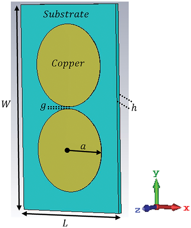
Figure 1: Geometries of the 3-D PCD antenna element
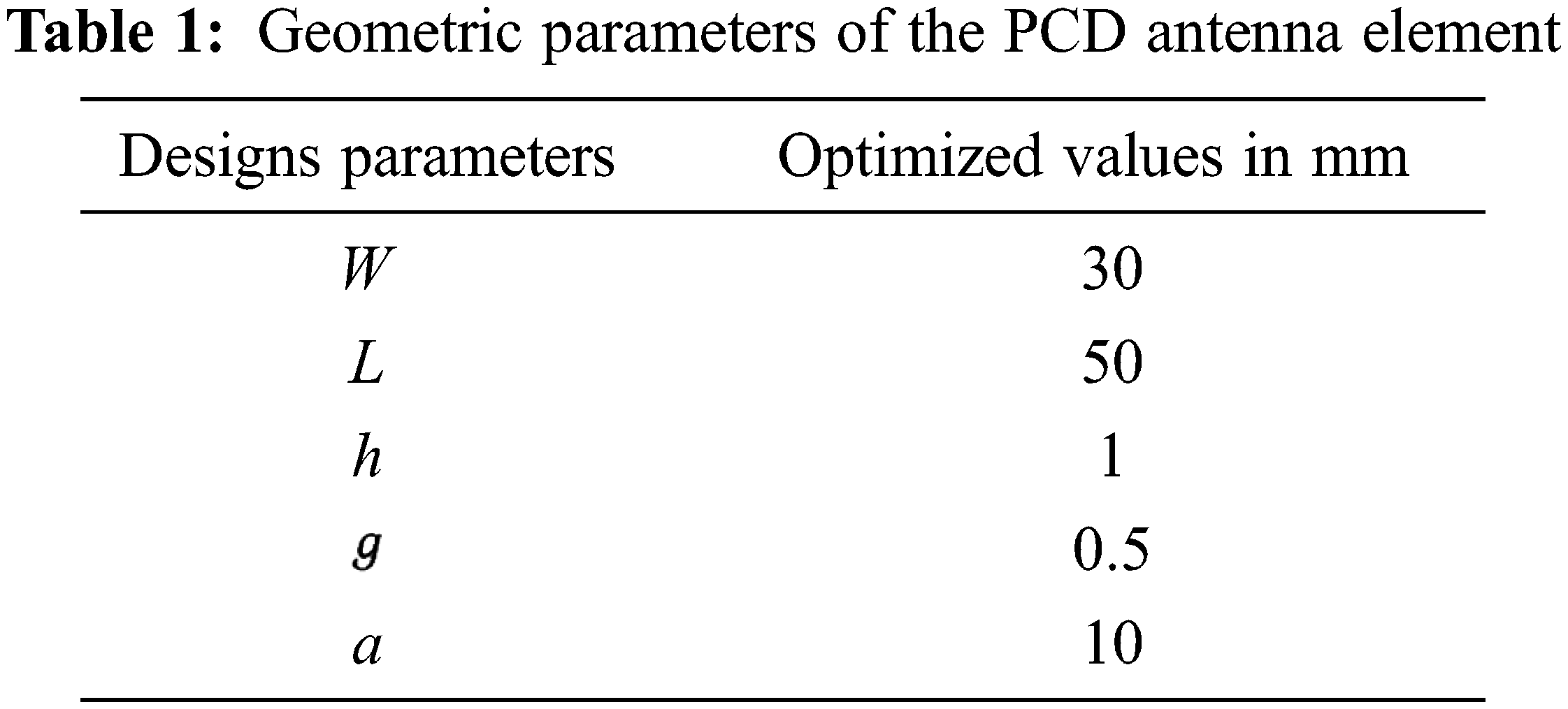
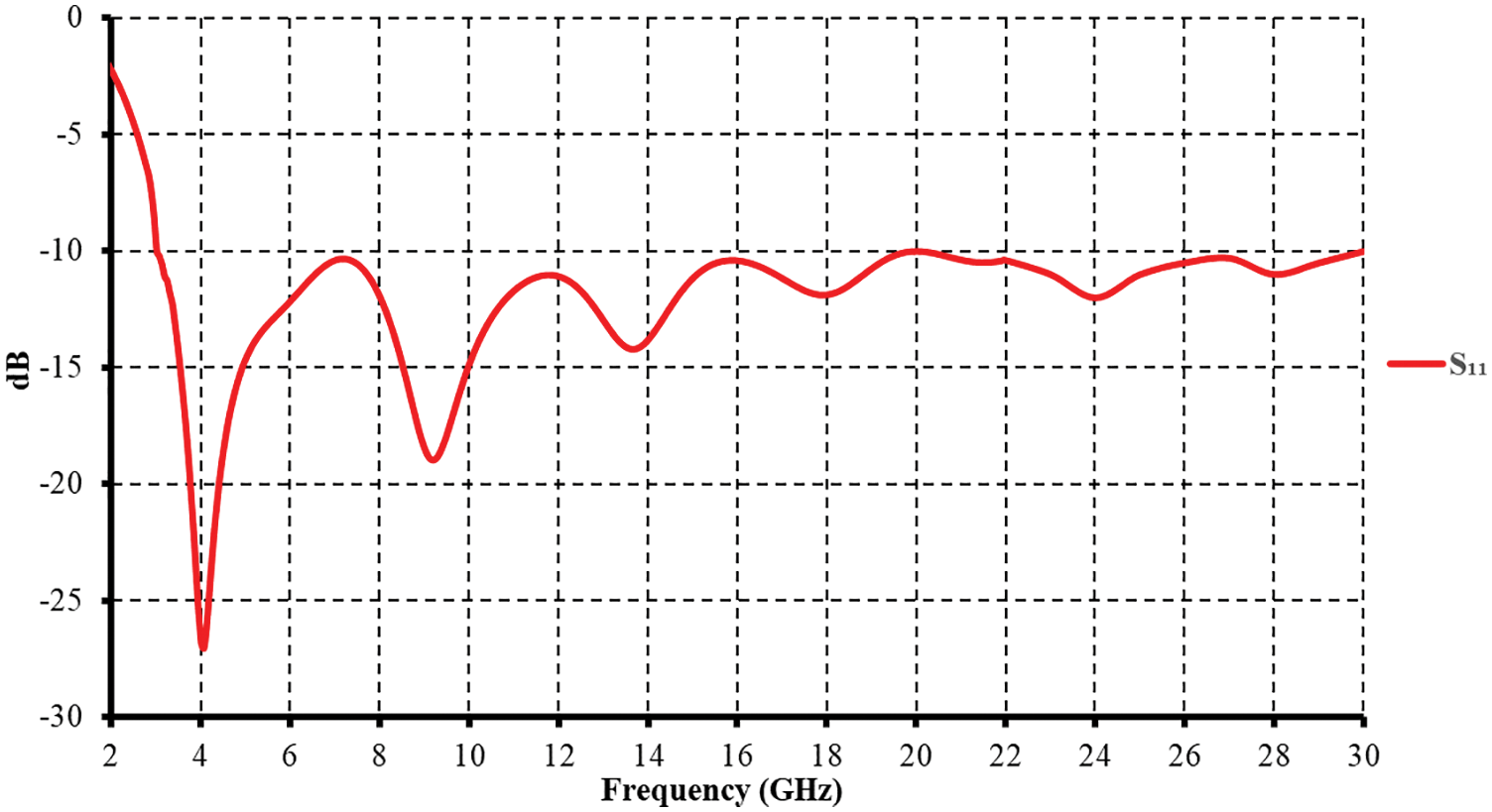
Figure 2: Simulated return loss for the proposed antenna shown in Fig. 1
Generally, a dipole antenna with a good radiation pattern has an adequate length of
The proposed antenna was found to have a frequency ratio of 1:10 for the impedance bandwidth obtained. This behavior can be primarily attributed to achieving a more uniform current distribution in the proposed antenna, as shown in Fig. 3.
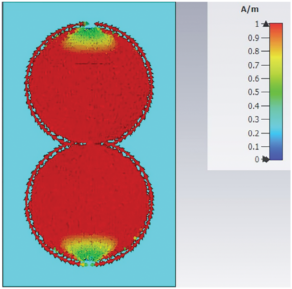
Figure 3: Simulated surface current distributions for the proposed antenna shown in Fig. 1 at 3 GHz
The radiation characteristics of the proposed antenna are also analyzed. Fig. 4 plots the simulated radiation pattern at 3 GHz. The gain variations in the azimuthal plane (x-y plane) greatly depend on the operating frequency; Fig. 5 shows the simulated gain for frequencies across the obtained impedance bandwidth. The antenna gain monotonically increases from approximately 2 to 5.5 dBi.
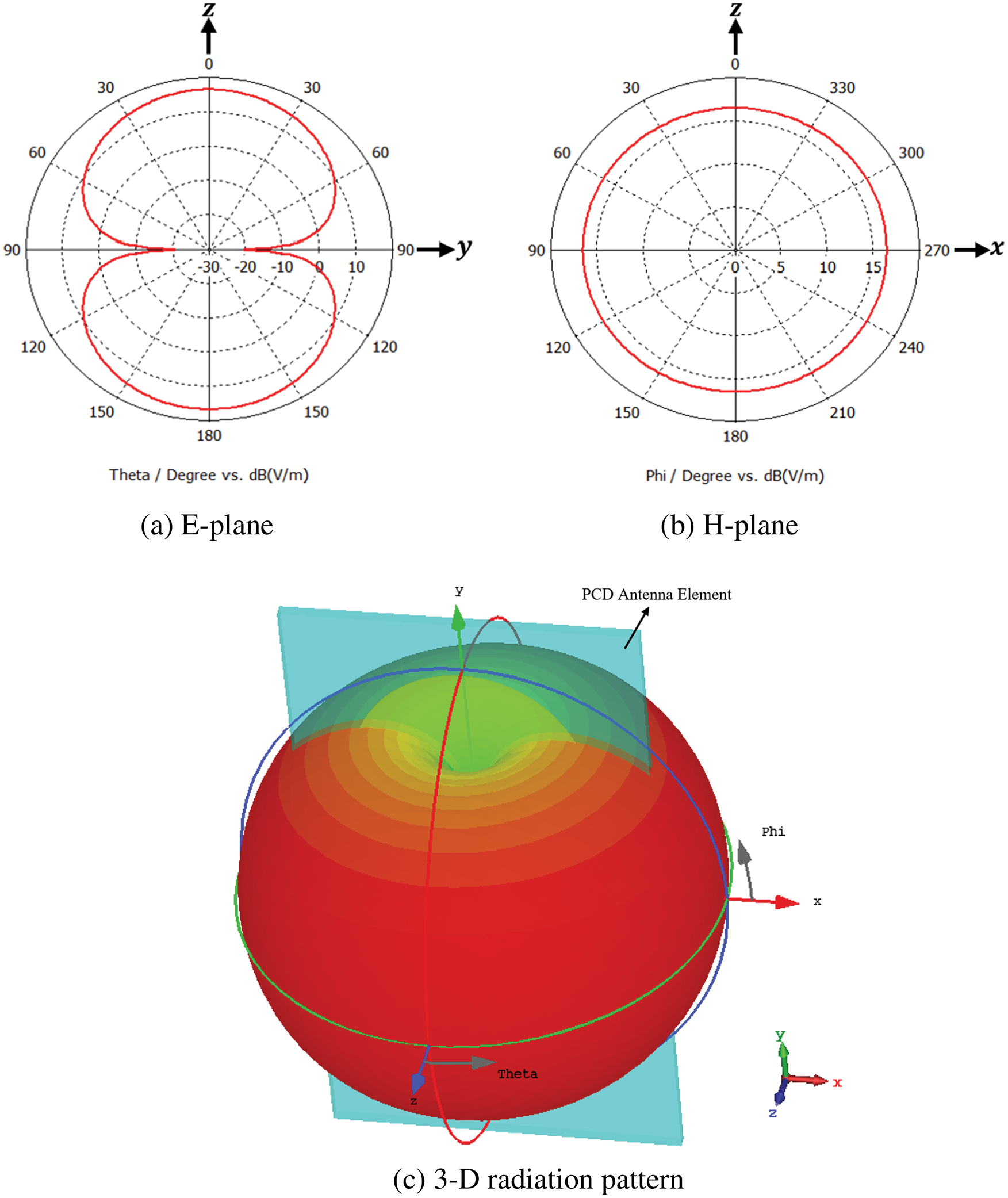
Figure 4: Simulated radiation patterns (E and H planes) at 3 GHz for the proposed antenna shown in Fig. 1
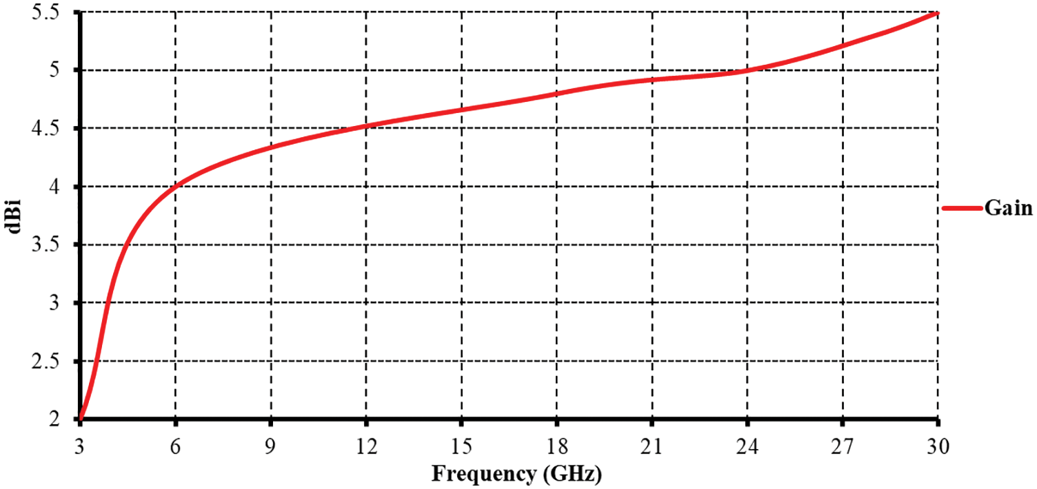
Figure 5: Simulated gain for the proposed antenna shown in Fig. 1
An electromagnetic wave carrying OAM exhibits a helical phase-front due to the azimuthal dependency of its spatial phase distribution. This distribution is described in the form
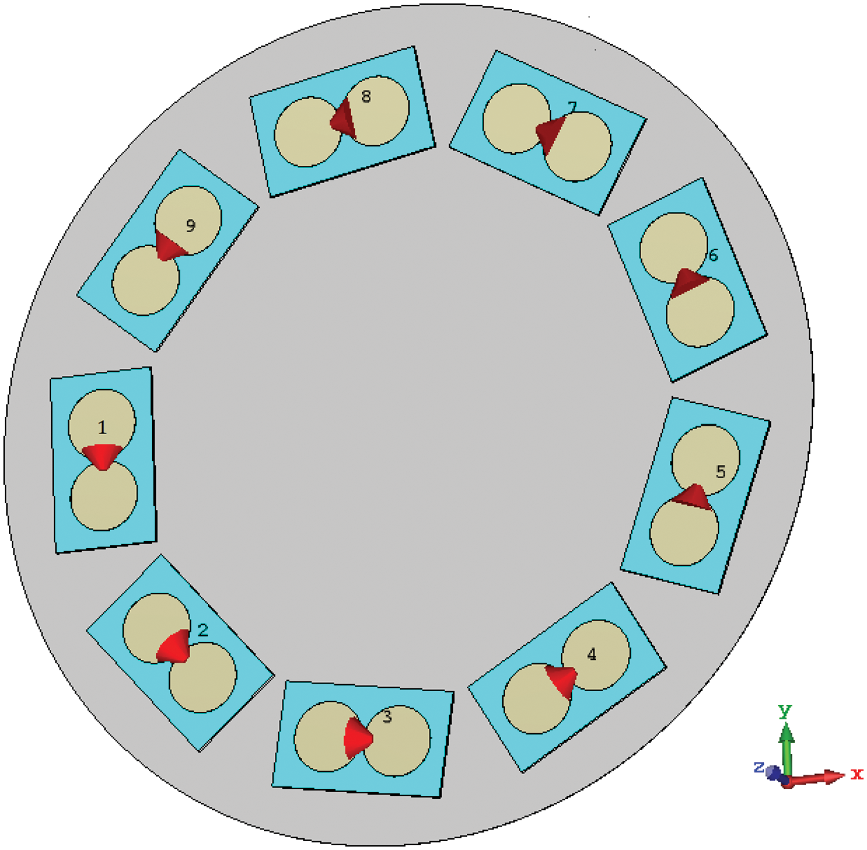
Figure 6: Circular array configuration including nine radiation PCD elements with disk reflector
To understand the propagation properties of the radiation produced by the proposed method, a mathematical formulation of the design and the generated wave are provided in this section. As stated in the previous section, the initial beam is constructed from a Bessel beam of OAM order m. The amplitude of the beam in the transverse propagation plane is characterized by a Bessel function of the first kind and
Having the field model under consideration, we proceed to form a beam by focusing the radiation in one direction. This is attained by partially annihilating the total radiation through pinning
Fig. 7 shows, as an example, the (normalized) field intensity of a second-order OAM wave. In the upper part of the figure, where all elements of the array were activated, the radiation appears in the OAM expected form as a complete annular ring. Whereas, the lower part of the figure shows five nulls, which represent those PCD elements that were turned off; clearly, part of the previously shown complete intensity ring is dismissed now.
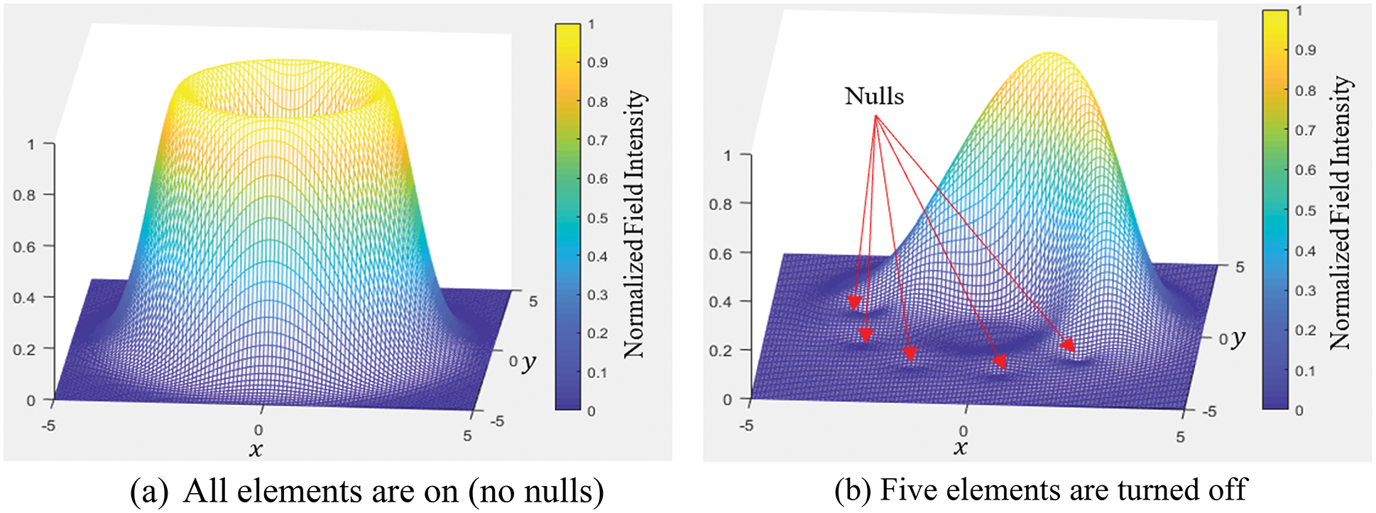
Figure 7: Normalized wave intensity for an OAM wave (m = 2) produced by an array of nine elements
The products in expression (1) can be reformulated as a sum of terms:
where
for
where
where an additional Bessel function appeared after using the integral form [23]:
The radial integration in
This expression is valid for
To appreciate the capability of the steering method and to evaluate the credibility of the derived system model, we provide in this part results obtained from numerical simulations using CST Microwave Studio and MATLAB. Firstly, essential OAM wave generation is considered using an array of PCD. Then, we deal with beam steering as a method based on the generated OAM waves.
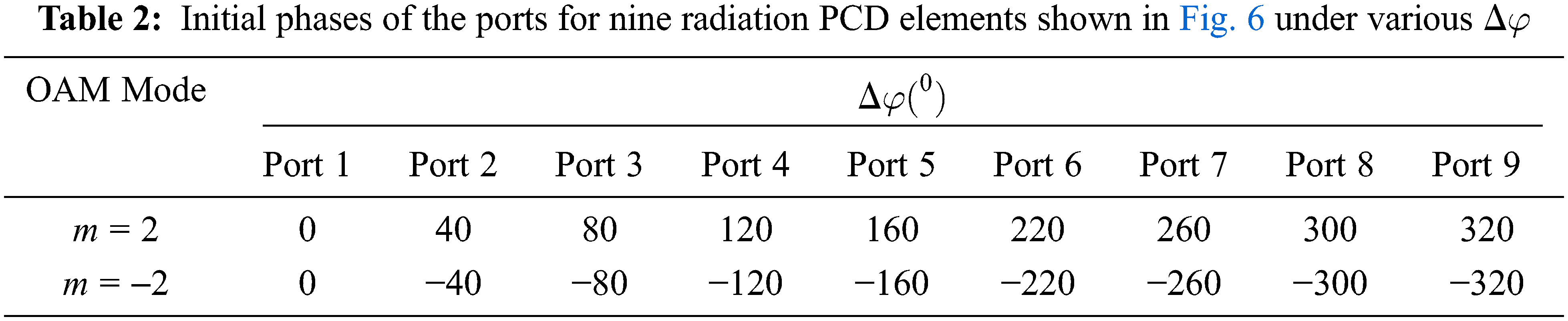
Following the design criteria, nine radiation PCD elements are placed over a circular circumference with a radius of 80 mm. Upon appropriate feeding of the PCD elements, an OAM wave is generated. The radiation pattern for a second-order OAM wave (m = 2) is shown in Fig. 8. The OAM properties of the generated wave are demonstrated through phase and amplitude distributions in Figs. 9a and 9b, respectively. The phase distribution in Fig. 9a shows two complete
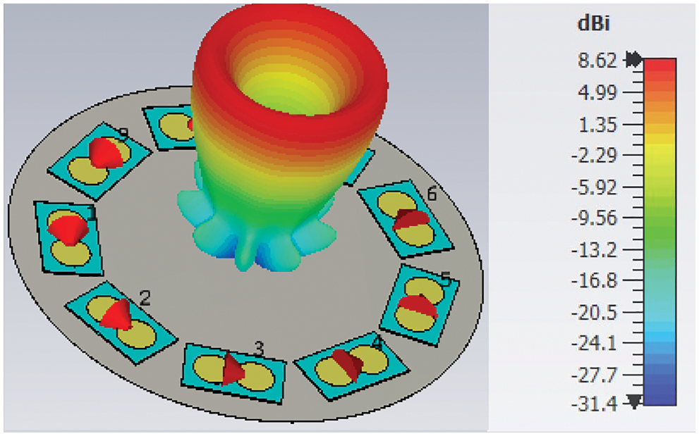
Figure 8: The simulated radiation pattern of an OAM wave (m = 2) at 3 GHz
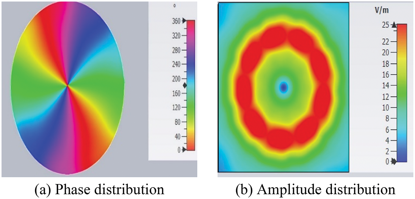
Figure 9: Phase and amplitude distributions of an OAM wave (
4.2 Beam Steering Based on OAM Waves
Azimuthal and elevation beam steering are attained electrically by controlling the excitation of the array of PCD elements. When a group of the PCD elements is turned off, the radiation is confined to a small part of the intensity ring. This is demonstrated in Fig. 10. When three array PCD elements (1, 8, and 9) are turned off, the radiated intensity (which formed a complete ring, see Fig. 7) is forced to follow a specific path (30° azimuthal angle in Fig. 10). Changing the off PCD elements changed the radiation azimuthal direction. Two more examples are shown in Figs. 11 and 12 for 90° and 210° azimuthal steering, respectively.
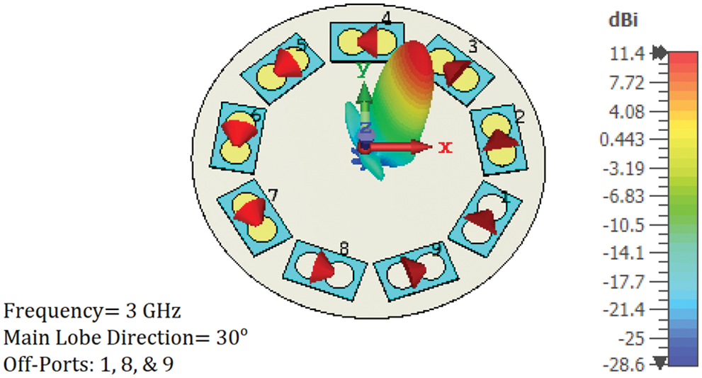
Figure 10: 3-D simulated radiation pattern at 3 GHz. directivity beam steering at a 30° azimuthal angle was achieved by turning off three array PCD elements (1, 8, and 9)
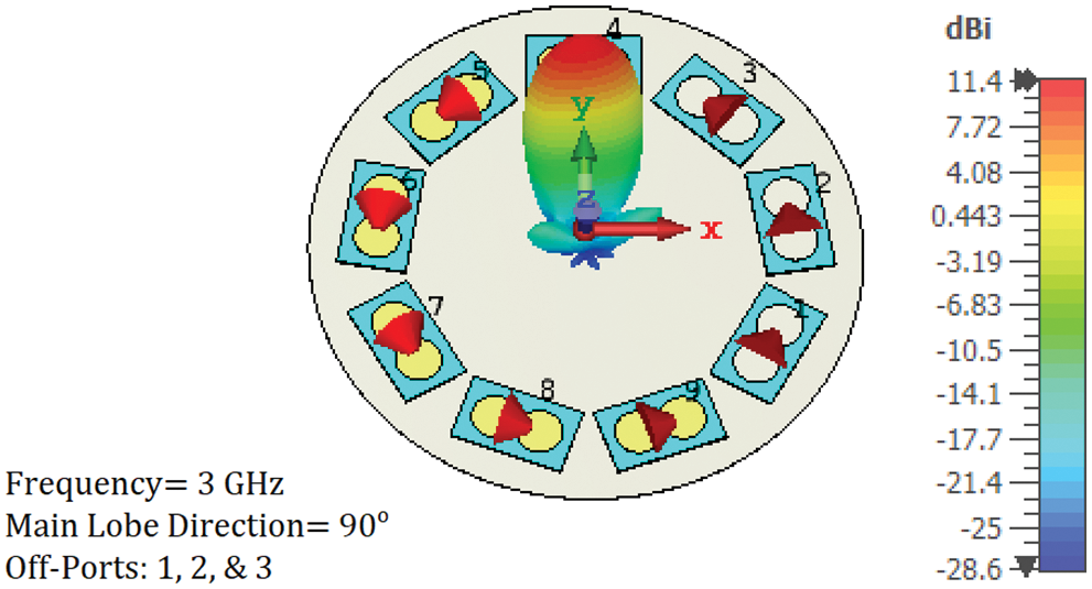
Figure 11: 3-D simulated radiation pattern at 3 GHz. Directivity beam steering at a 90° azimuthal angle was achieved by turning off three array PCD elements (1, 2, and 3)
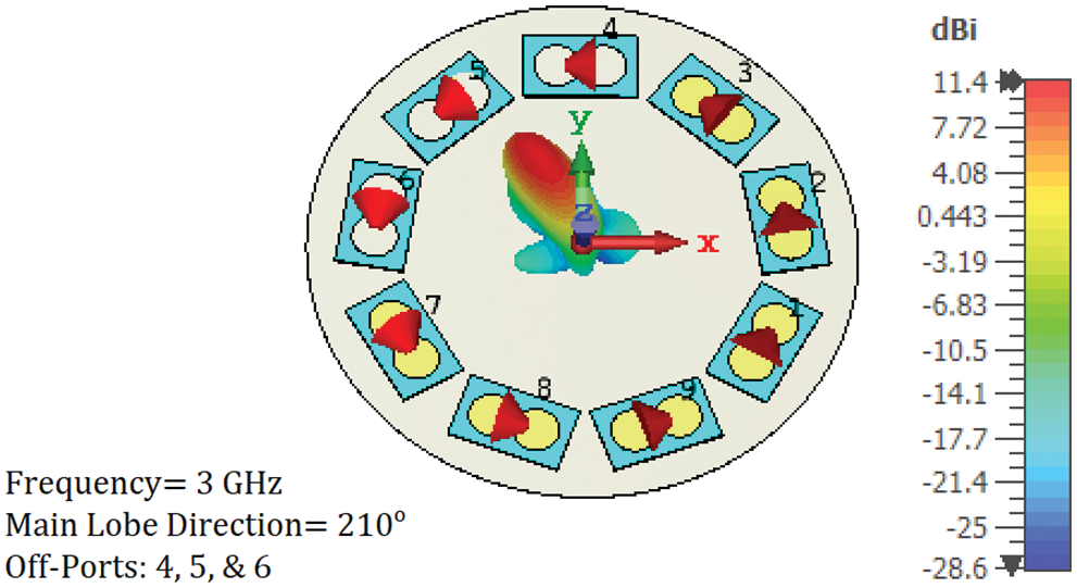
Figure 12: 3-D simulated radiation pattern at 3 GHz. Directivity beam steering at a 210°azimuthal angle was achieved by turning off three array PCD elements (4, 5, and 6)
The polar plot given in Fig. 13 demonstrates the ability of the designed configuration to steer the beam over different elevations. The steering method, as explained previously, relies on changing the excitation phase to change the wave OAM order. This, in turn, confines the radiation to different elevations. A wave carrying a higher OAM order diverged more than one with a smaller order. This intrinsic property of the OAM wave is exploited to focus the beam onto the desired elevation. Regarding the elevation step size, it is clear from Fig. 13 that this step is limited to a minimum resolution, which might not be sufficient for specific scanning applications. To obtain finer control of the step size, it is suggested (even not studied in this paper) that fractional OAM orders are used; this, however, needs further modification to the OAM wave generation method. Another solution could be raising the array aperture size or, equivalently, the number of PCD elements in the array. This would make it possible to focus the radiation over a smaller dynamic range with smaller elevation steps between successive OAM orders. Two scenarios are deployed to prove the previous concept, as demonstrated in Fig. 14. In the first scenario, eighteen PCD elements are set up in the array leading to a change in elevation angle from 12° to 18° in corresponding to OAM order change from m = 2 to 3, respectively. In the second scenario, nine PCD elements are installed, leading to a more significant jump in the elevation angle from 17° to 43°, using the exact order change as in the first scenario. The following two findings should also be noted: 1) when the OAM order approaches the maximum limit that is allowed by the number of elements in the array, the side lobes begin to rise notably. This is obvious in Fig. 13, by noting that the 6th. OAM order has a relatively larger side lobe than the other (lower) orders. 2) An enhancement in the gain by 3.5 dBi is achieved upon turning some array elements off. For instance, the gain changed from 8 dBi when no elements were turned off (see Fig. 8) to 11.4 dBi when three elements were turned off (see Figs. 10–12). This rise in gain can be explained as the turned-off elements functioning as reflectors that enhance the energy flow in the steered beam direction.
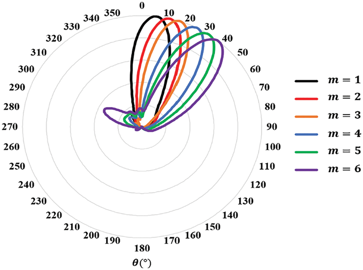
Figure 13: A polar plot of the normalized beam steering radiation characteristic of the eighteen PCD elements with different OAM orders
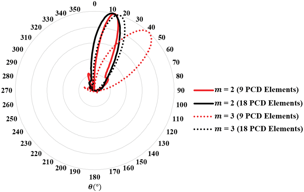
Figure 14: Polar plots of normalized beams for different PCD element numbers and OAM orders. The resolution of elevation scanning can be increased by raising the PCD elements in the array
Fig. 15 shows the field distribution over a cross-section taken perpendicular to the propagation axis at 3 m from the array. The CST Microwave Studio simulation result of the propagated field is shown in Fig. 15a. A similar result is shown in Fig. 15b, obtained using MATLAB to plot the field derived in the mathematical model of Section 3. The results are comparable to a reasonable extent. However, some differences can be attributed to the nulls used in modeling the turned-off antenna elements. In contrast, the nulls were just considered in the mathematical model as points in the field distribution, the actual size of an off element is larger than being just a point.
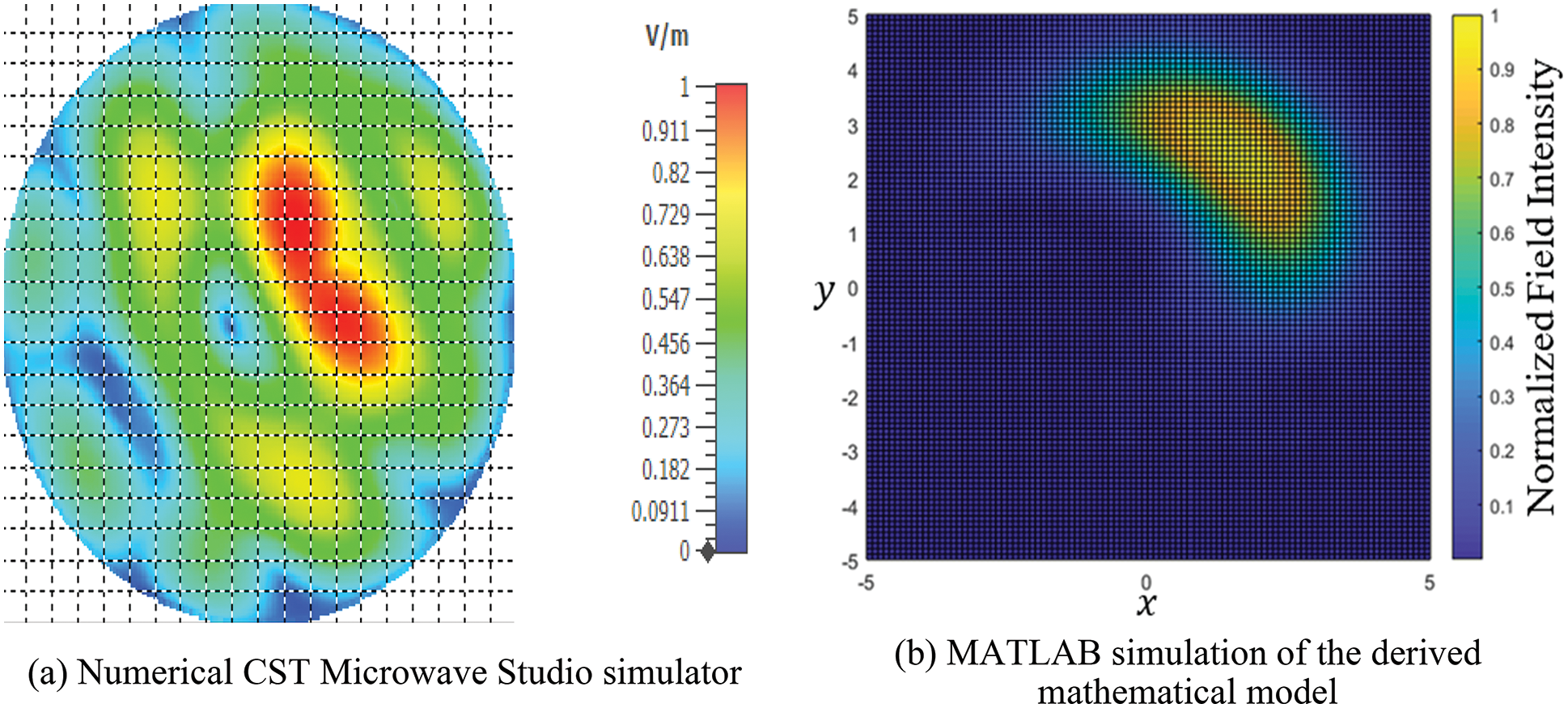
Figure 15: Transverse section showing the hotspot of a beam after propagation by 3 m. The beam was steered over the horizon and directed toward a specific elevation using an OAM wave (m = 2)
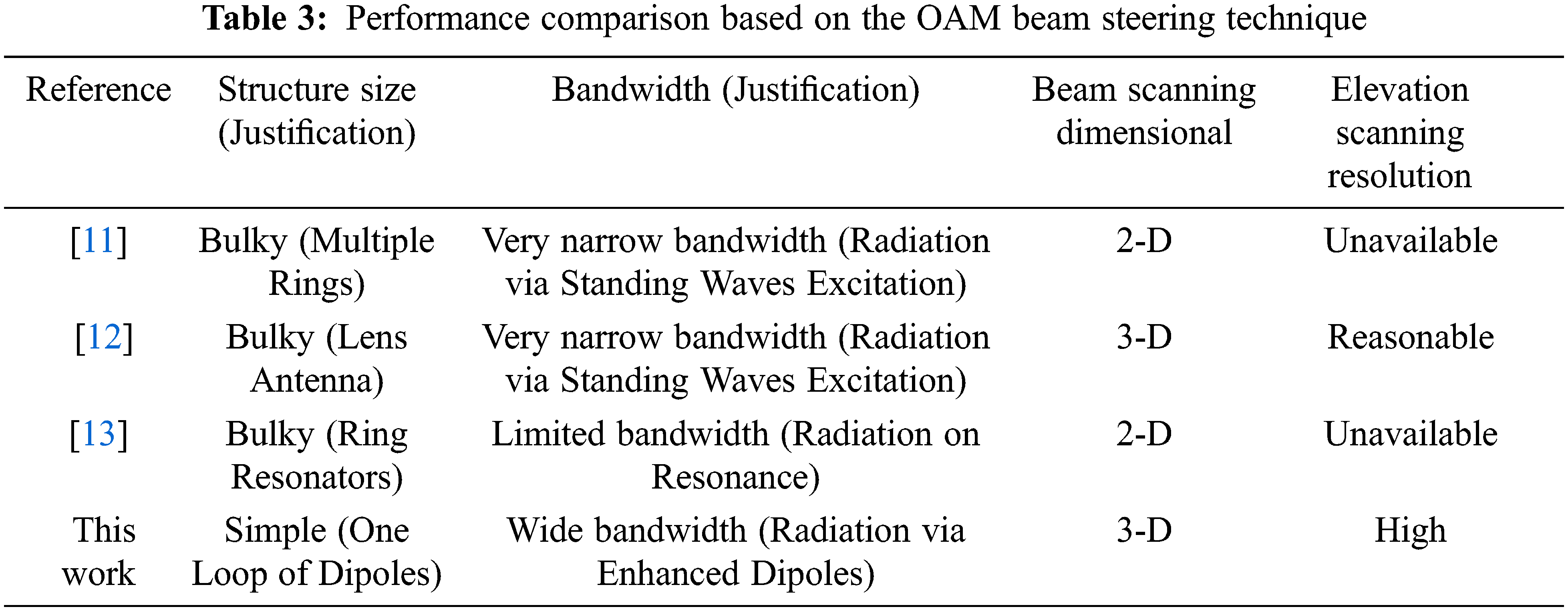
In the next step, we expand the comparison to include performance comparison based on the OAM steering technique. In this case, comparing structure size, bandwidth, beam scanning dimensional, and elevation scanning resolution have been considered. Table 3 summarizes the results. The systems in [11–13] are considered in the comparison.
In this paper, we presented a simple method for electrically steering electromagnetic radiation in specific elevations and azimuthal directions. Constructing an OAM beam and annihilating part of it offered a wide dynamic steering range. Essential antenna elements of the array were designed to increase the system frequency range of operation and enhance the efficiency of radiation. We evaluated electrical beam steering by generating an OAM wave using PCD array antennas at 3 GHz as a testing point from a wide bandwidth range between 3 and 30 GHz. By achieving different OAM orders, we obtained different elevation directions. We could focus the radiation on a specific azimuthal direction by pinning N-nulls in the field of the generated wave by turning off some PCD antenna elements. Such focusing caused an increase in gain from 8.5 dBi to approximately 11.5 dBi. The system was mathematically and numerically modeled and studied under propagation conditions. Several aspects, including the elevation scanning resolution, were studied.
Funding Statement: The authors received no specific funding for this study.
Conflicts of Interest: The authors declare that they have no conflicts of interest to report regarding the present study.
References
1. J. Hasch, E. Topak, R. Schnabel, T. Zwick, R. Weigel et al., “Millimeter-wave technology for automotive radar sensors in the 77 GHz frequency band,” IEEE Transactions on Microwave Theory Technology, vol. 60, no. 3, pp. 845–860, 2012. [Google Scholar]
2. V. G. Buendía, D. Comite, S. K. Podilchak, M. Kuznetcov, A. P. Freundorfer et al., “2-D planar leaky-wave antenna with fixed frequency beam steering through broadside,” in 2020 14th European Conf. on Antennas and Propagation (EuCAP), Copenhagen, Denmark, pp. 1–4, 2020. [Google Scholar]
3. M. Skolnik, Radar Handbook, 3rd ed., New York, NY, USA: McGraw-Hill Education, 2008. [Google Scholar]
4. G. Lei, M. L. Kawi and C. Shichang, “360° beam-steering reconfigurable wideband substrate integrated waveguide horn antenna,” IEEE Transactions on Antennas and Propagation, vol. 64, no. 12, pp. 5005–5011, 2016. [Google Scholar]
5. H. Zahra, M. Hussain, S. I. Naqvi, S. M. Abbas and S. Mukhopadhyay, “A simple monopole antenna with a switchable beam for 5G millimeter-wave communication systems,” Electronics, vol. 10, no. 22, pp. 2870, 2021. [Google Scholar]
6. L. Han, G. Cheng, G. Han, R. Ma and W. Zhang, “Electronically beam-steering antenna with active frequency-selective surface,” IEEE Antennas and Wireless Propagation Letters, vol. 18, no. 1, pp. 108–112, 2019. [Google Scholar]
7. D. K. Karmokar, K. P. Esselle and S. G. Hay, “Fixed-frequency beam steering of microstrip leaky-wave antennas using binary switches,” IEEE Transactions on Antennas and Propagation, vol. 64, no. 6, pp. 2146–2154, 2016. [Google Scholar]
8. D. Comite, S. Podilchak, P. Baccarelli, P. Burghignoli, A. Galli et al., “A dual-layer planar leaky-wave antenna designed for linear scanning through broadside,” IEEE Antennas Wireless Propagation Letters, vol. 16, pp. 1106–1110, 2016. [Google Scholar]
9. S. L. Chen, D. K. Karmokar, P. Y. Qin, R. W. Ziolkowski and Y. J. Guo, “Polarization-reconfigurable leaky-wave antenna with continuous beam scanning through broadside,” IEEE Transactions on Antennas and Propagation, vol. 68, no. 1, pp. 121–133, 2019. [Google Scholar]
10. D. Comite, P. Burghignoli, P. Baccarelli and A. Galli, “2-D beam scanning with cylindrical-leaky-wave-enhanced phased arrays,” IEEE Transactions on Antennas and Propagation, vol. 67, no. 6, pp. 3797–3808, 2019. [Google Scholar]
11. N. Qasem, A. Alamayreh and J. Rahhal, “Beam steering using OAM waves generated by a concentric circular loop antenna array,” Wireless Networks, vol. 27, no. 4, pp. 2431–2440, 2021. [Google Scholar]
12. A. Alamayreh and N. Qasem, “Lens antenna for 3D steering of an OAM-synthesized beam,” Wireless Networks, vol. 27, no. 8, pp. 5161–5171, 2021. [Google Scholar]
13. S. Zheng, Y. Chen, Z. Zhang, X. Jin, H. Chi et al., “Realization of beam steering based on plane spiral orbital angular momentum wave,” IEEE Transactions on Antennas and Propagation, vol. 66, no. 33, pp. 1352–1358, 2018. [Google Scholar]
14. Y. Yang, K. Guo, F. Shen, Y. Gong and Z. Guo, “Generating multiple OAM based on a nested dual-arm spiral antenna,” IEEE Access, vol. 7, pp. 138541–138547, 2019. [Google Scholar]
15. A. Alamayreh and N. Qasem, “Vortex beam generation in microwave band,” Progress in Electromagnetics Research C, vol. 107, pp. 49–63, 2021. [Google Scholar]
16. S. K. Noor, M. N. M. Yasin, A. M. Ismail, M. N. Osman, P. J. Soh et al., “A review of orbital angular momentum vortex waves for the next generation wireless communications,” IEEE Access, vol. 10, pp. 89465–89484, 2022. [Google Scholar]
17. L. Wang, W. Park, C. Yang, H. D. Brüns, D. G. Kam et al., “Wireless communication of radio waves carrying orbital angular momentum (OAM) above an infinite ground plane,” IEEE Transactions on Electromagnetic Compatibility, vol. 62, no. 5, pp. 2257–2264, 2020. [Google Scholar]
18. M. Alkhawatrah, A. Alamayreh and N. Qasem, “Cooperative relay networks based on the OAM technique for 5G applications,” Computer Systems Science and Engineering, vol. 44, no. 3, pp. 1911–1919, 2023. [Google Scholar]
19. A. Alamayreh, N. Qasem and J. S. Rahhal, “General configuration MIMO system with arbitrary OAM,” Electromagnetics, vol. 40, no. 5, pp. 343–353, 2020. [Google Scholar]
20. K. Liu, Y. Cheng, Y. Gao, X. Li, Y. Qin et al., “Super-resolution radar imaging based on experimental OAM beams,” Applied Physics Letters, vol. 110, no. 16, pp. 164102-1–164102-5, 2017. [Google Scholar]
21. H. Nazli, E. Bicak, B. Turetken and M. Sezgin, “An improved design of planar elliptical dipole antenna for UWB applications,” IEEE Antennas and Wireless Propagation Letters, vol. 9, pp. 264–267, 2010. [Google Scholar]
22. J. W. Goodman, Introduction to Fourier Optics, 4th ed., New York, NY, USA: W. H. Freeman, 2017. [Google Scholar]
23. I. S. Gradshteyn and I. M. Ryzhik, Table of Integrals, Series, and Products, 8th ed., Salt Lake City, UT, USA: Academic Press, 2014. [Google Scholar]
Cite This Article
 Copyright © 2023 The Author(s). Published by Tech Science Press.
This work is licensed under a Creative Commons Attribution 4.0 International License , which permits unrestricted use, distribution, and reproduction in any medium, provided the original work is properly cited.
 Downloads
 Citation Tools