
 Submit a Paper
 Propose a Special lssue
 Open Access
ARTICLE

Novel Double Modular Redundancy Based Fault-Tolerant FIR Filter for Image Denoising
1 Department of Electronics and Communication Engineering, Nehru Institute of Engineering and Technology, Coimbatore, 641105, India
2 Department of Computer Science and Engineering, KPR Institute of Engineering and Technology, Coimbatore, 641105, India
* Corresponding Author: V. S. Vaisakhi. Email:
Computer Systems Science and Engineering 2023, 46(1), 181-193. https://doi.org/10.32604/csse.2023.032514
Received 20 May 2022; Accepted 24 June 2022; Issue published 20 January 2023
 View Full Text
 Download PDF
Abstract
In signal processing and communication systems, digital filters are widely employed. In some circumstances, the reliability of those systems is crucial, necessitating the use of fault tolerant filter implementations. Many strategies have been presented throughout the years to achieve fault tolerance by utilising the structure and properties of the filters. As technology advances, more complicated systems with several filters become possible. Some of the filters in those complicated systems frequently function in parallel, for example, by applying the same filter to various input signals. Recently, a simple strategy for achieving fault tolerance that takes advantage of the availability of parallel filters was given. Many fault-tolerant ways that take advantage of the filter’s structure and properties have been proposed throughout the years. The primary idea is to use structured authentication scan chains to study the internal states of finite impulse response (FIR) components in order to detect and recover the exact state of faulty modules through the state of non-faulty modules. Finally, a simple solution of Double modular redundancy (DMR) based fault tolerance was developed that takes advantage of the availability of parallel filters for image denoising. This approach is expanded in this short to display how parallel filters can be protected using error correction codes (ECCs) in which each filter is comparable to a bit in a standard ECC. “Advanced error recovery for parallel systems,” the suggested technique, can find and eliminate hidden defects in FIR modules, and also restore the system from multiple failures impacting two FIR modules. From the implementation, Xilinx ISE 14.7 was found to have given significant error reduction capability in the fault calculations and reduction in the area which reduces the cost of implementation. Faults were introduced in all the outputs of the functional filters and found that the fault in every output is corrected.Keywords
Embedded systems are becoming more prevalent in security applications such as aircraft, control systems, and patient life-support monitoring. Both time and fault tolerance are usually required in this type of system. Embedded systems should be provided with appropriate error detection and mitigation solutions to [1] fulfill the dependability criterion. However, having a higher part of consistency and satisfying timeliness criteria are opposing goals, i.e., improving consistency may negatively influence fulfilling deadlines. The general dependability of rollover rehabilitation systems, for example, is increased; nevertheless, as the expected response time increases, the likelihood of exceeding deadlines for specific applications increases as well. In particular, for safety-critical systems, boosting system consistency without taking into account real-time restrictions is unjustifiable. As a result, implementing fault-tolerant algorithms in embedded processors with minimal efficiency overhead is critical [2].
Electronic circuits are becoming more common in high-reliability requirements such as automotive, medicinal, and space. Circuits in these criteria must give some level of fault tolerance. The inherent reliability issues of modern Complementary Metal Oxide Semiconductor (CMOS) technologies, such as production variances and soft mistakes, exacerbate this necessity. A circuit can be protected from mistakes using a variety of approaches. These include everything from changes to the circuits’ production process to creating redundancies at the logic or structure level to guarantee that failures do not influence the overall performance of the system. Triple modular redundancy (TMR) can be used to add redundancy [3]. The TMR, which triples the design and boosts the circuit’s power, isn’t appropriate for every application. Once the system to be secured has algorithmic or physical qualities, exploiting those features to provide fault tolerance can be a preferable choice. Signal processing circuits are one example, for which particular methodologies have been proposed over time.
Error Detection for Soft Errors Circuits is becoming more susceptible to many types of disturbances as a result of anemometric technology. Soft mistakes, formerly a source of worry for space programs, have now become a ground-level consistency problem. Alpha particles and atmospheric neutrons create single-event upsets (SEU) in storage cells, flip-flops, and latches, as well as single-event transients (SET) generated in combination circuitry and detected by latches and flip-flops linked with the output of the circuit [4]. To meet this problem, a designer will need a number of fault-tolerant reduction strategies that may be tailored to different circuit layouts, design architectures, and design limitations. Finally, a simple solution of Double modular redundancy (DMR) based fault tolerance was developed that takes advantage of the availability of parallel filters for image denoising. This approach is expanded in this short to display how parallel FIR filters can be defended using error correction codes (ECCs) in which each filter is comparable to a bit in a standard ECC.
The remaining of the paper is systemized as follows: Section 2 defines the several SEU and SET mitigation strategies that could aid the designer are detailed in this study. The fault-tolerant techniques of the Triple modular redundancy (TMR) are discussed in Section 3. Section 4 describes the proposed method of the Double Error Correction System. Simulation results are carried out in Section 5 and the summary of the work is arrived at in Section 6.
Several mitigation strategies of SEU and SET that might aid the research are detailed in this study. Deep submicron integrated circuits reliability has been substantially lowered as a result of drastic device shrinkage, greater complexity, reduced power supply, and higher operational speeds that accompanied the technical progression to anemometric technology.
Alpha particles created by radioactivity element traces contained in manufacturing, bonding, and casting components induce soft errors, as well as atmospheric neutrons made by cosmic ray interactions with the earth’s atmosphere, which are a serious issue [5]. Unlike alpha rays, which are partially filled and generate a path of unpaired electrons as they travel through an integrated circuit, protons are electrically isolated and hence cause soft faults: A slightly elevated neutron could collide with silica, air, or another element in the device, resulting in high-energy particles that could cause soft errors. It’s worth noting that the contact can produce a slew of subsequent particles that can affect multiple circuit nodes at once. Thermal neutrons may also be a substantial cause of soft faults; however, this cause has been addressed in current methods by removing borophosphosilicate glass (BPSG) [6]. When a sensitivity node, like the drains of off transistors, is in close proximity to an electrically charged particle’s ionized path, it accumulates a large portion of the produced charge carriers (holes or electrons), resulting in a passing current pulse on this lump. The cell type that the afflicted node belongs to determine the influence of this pulse. A highly intense pulse can cause a single-event upset (SEU) in a database unit (e.g., a storage cell, latches, or a flip-flop).
The suggested technique in [7] makes use of the linearity of filters to construct an error correction mechanism. Detecting and fixing problems in signal processing, such as crucial reliability, is difficult, which increases the usage of fault tolerant technology. Several filters running in parallel are common in modern signal processing circuits. An area efficient strategy for detecting and correcting single mistakes is proposed. To discover and repair problems, the technique employs SOS-ECC checks on the parallel FFT outputs. To detect and find problems, SOS checks are utilised, and a simple parity FFT is used for repair. The faults can be detected and located using either a parsvel’s check per FFT or a group of SOS checks that constitute an ECC. When compared to previous techniques, this technique can detect and rectify only single bit errors and reduced area results in high speed.
Control Feedback Loop Error Decimation (CFLED) is a revolutionary way for fault tolerance methodology for digital pipelined data-paths proposed in [8], which minimises the error magnitude at the outputs. From a control standpoint, the data-path is viewed as a process that is impacted by perturbations or defects. We develop feedback control loops based on the corresponding dynamic model in order to mitigate the influence of faults on the output. Correction loops apply correction factors to chosen data-path registers from rewinded execution blocks. We evaluate the cost and reliability of the suggested methodology to the typical triple modular redundancy on the data-path of a controller designed for a 2-degree of freedom robot arm. The method we suggest for Field Programmable Gate Array (FPGA) technology employs 30% fewer slices than Triple Modular Redundancy (TMR), while having one-third fewer digital signal processing blocks. Our approach improves reliability and error detection, according to simulation data.3 Fault-Tolerant Techniques.
TMR is an eminent and commonly utilized fault-resilient technology in security applications [9]. Traditional TMR systems, which consist of 3 modules of redundancy and their outputs, have significant flaws that must be solved before they can be used in safety-critical applications. The traditional TMR’s inability to cope with TMR failures is a serious flaw. TMR failure occurs when many malfunctioning modules or a faulty voter [10] cause a TMR system to fail. Although colliding with 2 different duplicate flip-flops in a TMR device is highly improbable, colliding with two components in a TMR network is not frequent when the device is operating in a severe atmosphere for an extended period of time. If two distinct faults arrive in two separate modules and neither of them is overwritten, a TMR failure may occur. The absence of proper restoration mechanisms considerably increases the likelihood of TMR failure in long-term applications. It must be supplied with a temporary error retrieval approach to overcome this problem. The majority of past TMR-based error recovery techniques have relied on retry mechanisms. These techniques, on the other hand, are not ideal for applications with tight deadlines, as re-computation may result in job completion after the deadline has passed [11].
Digital filters are the most widely used image processing systems, and various methods to protect them from errors have been presented. FIR filters have been the focus of the majority of them. For instance, reduced precision duplicates [12] have been proposed to lower the expense of adopting modular redundancy in Filter design. To detect flaws, a connection between the storage components of an FIR filter and the data patterns was used. FIR characteristics have also been used to generate fault tolerance at the word level in other systems. Residual numbering methods and numerical codes have been devised to protect filters. Finally, using alternative FIR filter implementation architectures to fix faults with only one redundant module has been suggested. The integrity of a single filter is addressed in all of the strategies outlined thus far [13].
However, systems with many filters operating in parallel are becoming more popular. This is the case with many current communication systems, as well as filter banks. By considering the parallel filters as a shielded block, the security of the filters in those systems may be managed at a superior stage. This concept was examined in, which evaluated at two adjacent filters with the same output that looked at different input signals. With only one duplicate copy, a single erroneous correction can be implemented. As a result, compared to TMR, a significant cost decrease was achieved. Two-of-five current coding systems [14] were used to enhance their concepts. To begin, he devised a system nomenclature that included the number of data bits and error-correction bits in each block.
TMR is a fault-resilient form of N-modular redundant in which three models execute an operation and the outcome is assessed by a huge majority mechanism to generate a unique output. If one of the three devices breaks, another two can take over and disguise the issue. This technique is commonly employed in fault-tolerant computer systems and can be expanded to a vast limit of redundancies, particularly software redundancies in the form of N-version programming. Since triple modular redundant equipment is quicker than Hamming error detection software, triple modular redundant hardware is used in some ECC memory (rather than the more typical Hamming code). TMR is commonly used in space satellite systems, while satellite Random Access Memory typically employs Hamming error correction. N-modular redundancy is applied in numerous communication systems as a simple form of forwarding error correction. For instance, consider the 5-modular redundancy communication system.
Three comparable logic devices (logic gates) are employed in TMR configuration, as stated by the Boolean function, and the triple modular redundancy is represented in Fig. 1. The data at the first circuit’s input is similar to the data at the second and third gates’ inputs. To avoid the accumulation of errors, TMR systems should be using data cleansing and rewriting flip-flops on a regular basis.
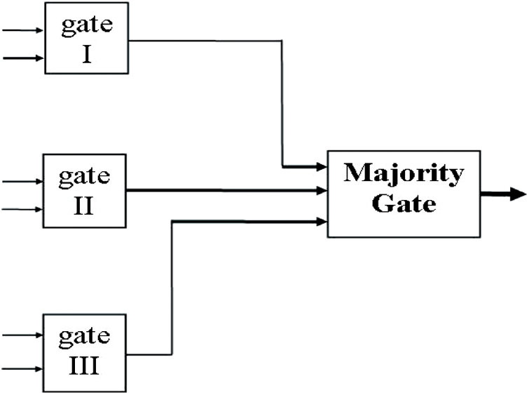
Figure 1: Logic gates of TMR
To achieve the equivalent range of given Boolean functions in TMR, three similar resulting combinations (logic gates) are required. The outcomes of the three circuits are equivalent if no circuit faults exist. However, the results of the three devices may differ due to circuit flaws. A Most Logic Gate is used to make out which of the devices’ outputs is the correct one.
If the Boolean function calculated by 3 similar logic devices has the value 1, then (a) all three circuits yield a value 1 output, and the dominant gate outcome has value 1, providing no circuits have collapsed. (b) If one circuit fails and outputs a 0 while the other two do not, the dominant gate output remains as 1, showing that it has the accurate amount. The result is the same whether the Boolean function calculated by the three exactly equal circuits returns a value of 0. As a consequence, as long as only one of the three comparable circuit designs fails, the majority gate output is assumed to be accurate. To avoid the development of errors, TMR systems should be using cleaning rewrite flip-flops on a regular basis.
The majority gate may collapse. Is there a method to hide your malfunction? In other terms, who protects the guardians is a duplication of the voters in only some TMR devices, like the Saturn Launch Vehicle Digital Computer and operational TMR processes. In each copy of the TMR logic’s subsequent phase, three voters are used. Such systems may not have a unique point of malfunction.
The majority gate is a simple circuit with a lower chance of error than several of the three gates that create the Boolean expression, in comparison to the relatively complex Boolean values produced in triple by the TMR method. There is only one voter in other systems. In such a system, if the voter fails, the entire system fails. The voter, on the other hand, is far more trustworthy than the other TMR component in a competent TMR system.
3.3 Implementation of Fault-Tolerant Parallel Filter
It is based on four FIR filters having the same response [H]. These four filters are given with different inputs x1, x2, x3, and x4 each of which is of n bit size [15]. These four inputs are coded to get x5, x6, and x7 as given in Eqs. (1) to (3).
In parallel to the above four filters, another three redundant filters having the same response as the previous ones are added in parallel [16]. The inputs to these redundant filters are x5, x6, and x7. These four filters are given with different inputs x1, x2, x3, and x4 each of which is of n bit size. These four inputs are coded to get x5, x6, and x7.
The outputs from these seven filters y1, y2, y3, y4, z1, z2, and z3 are applied to the single fault correction block. The outputs with correction, if any, are obtained as yc1, yc2, yc3, and yc4. The existing scheme is shown in Fig. 2 [17].
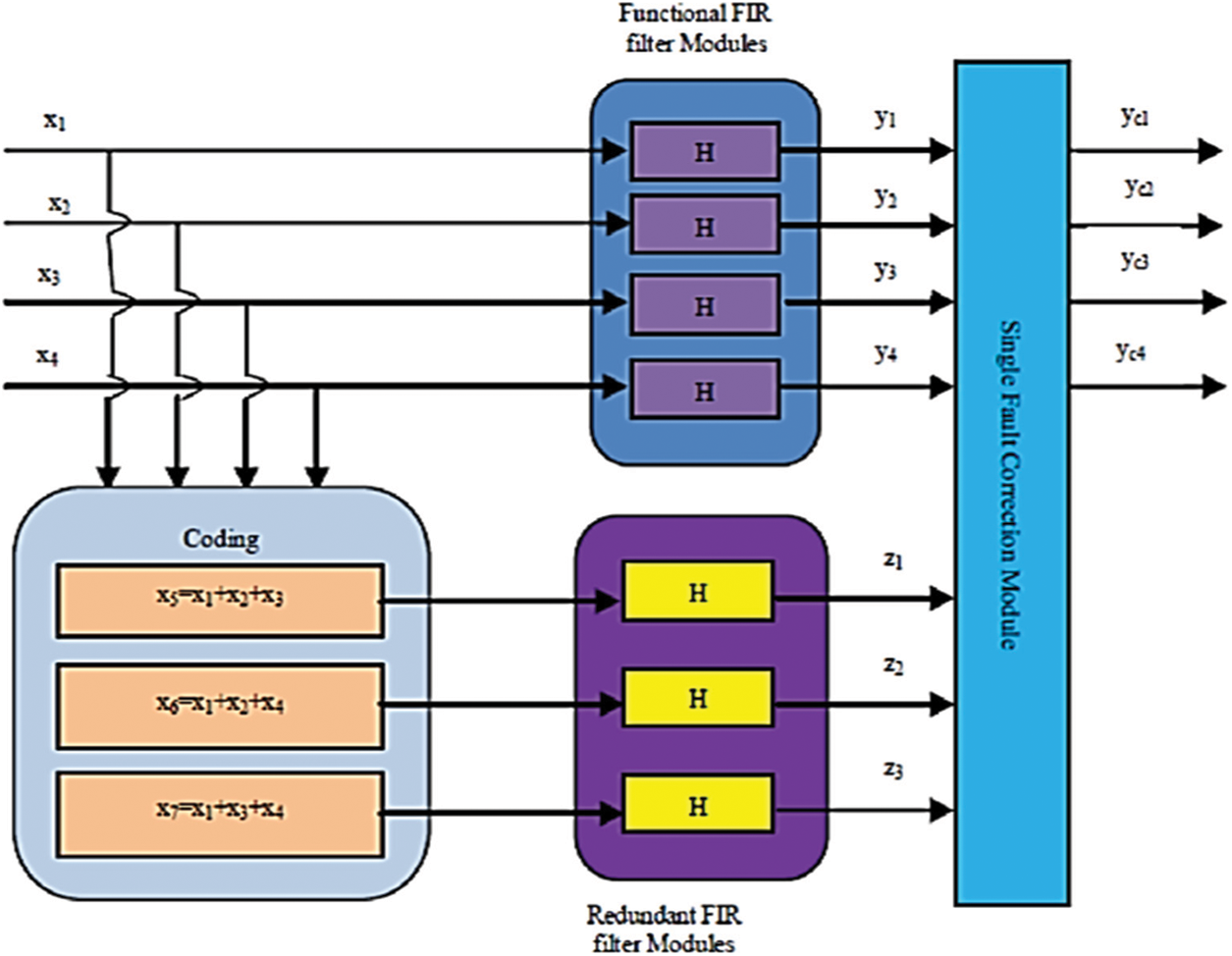
Figure 2: Three redundant modules
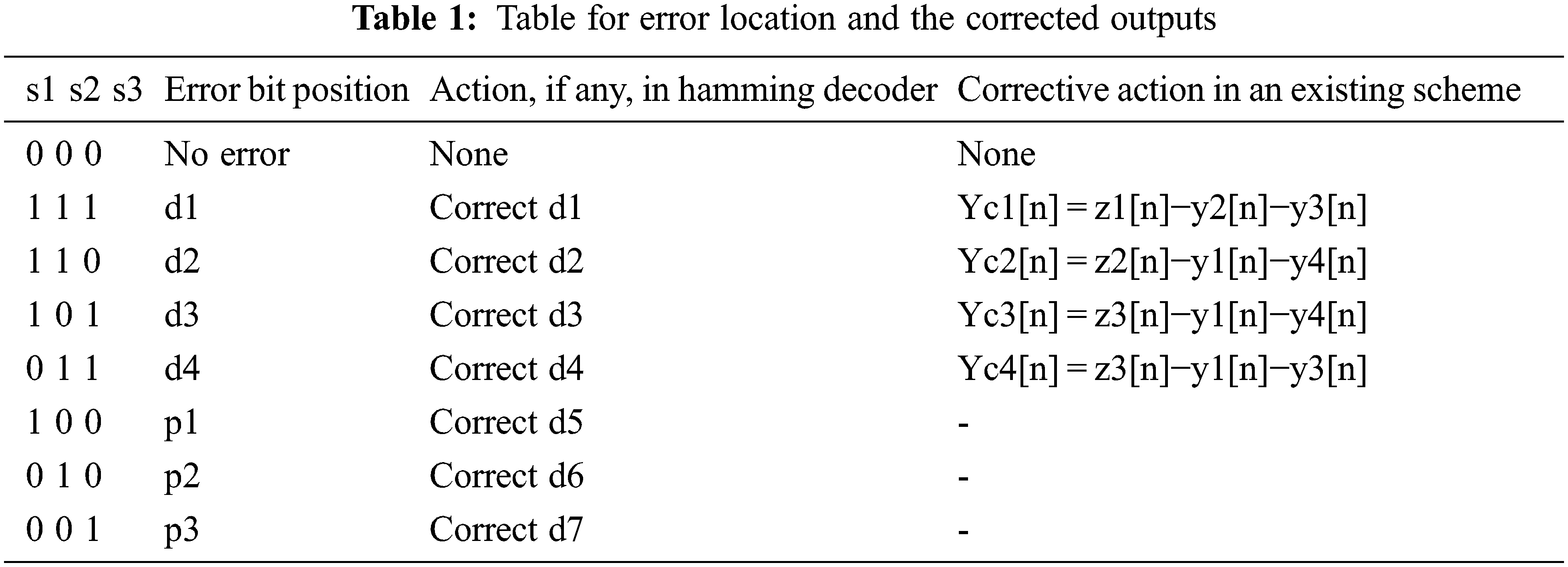
The correction block acts as a hamming decoder considering y1, y2, y3, and y4 as data bits and z1, z2, and z3 as parity bits. Based on this concept, the syndrome is generated. This block can correct one error output at the maximum from any one of y1, y2, y3, and y4. The corrected outputs are obtained as yc1, yc2, yc3, and yc4. Table 1 shows the Table for error location and the corrected outputs.
This is similar to how the overhead of standard ECCs diminishes as the block size grows. The TMR system, which consists of three duplicated components and a voter at the modules’ terminals, has a number of problems that must be corrected before it can be employed in a security application.
When a TMR method is operating in a hostile atmosphere for an extended duration of time, the likelihood of two energetic particles colliding with two modules is not insignificant. This method presumes that fault may occur in the output of any one of the four filters at a time and hence corrects the same, providing fault tolerance for a single faulty output from any one of the filters. This method presumes that fault may occur in the output of any one of the four filters at a time and hence corrects the same, providing fault tolerance for a single faulty output from any one of the filters. In parallel to the above four filters, another three redundant filters having the same response as the previous ones are added in parallel [18].
4 Proposed Method of Double Modular Redundancy (DMR) System
The proposed scheme of DMR employs only two redundant filters instead of three in the existing scheme and as such reduces the area on the chip [19]. It can correct errors in the outputs of the filters only in any one of the outputs y1, y2, y3, and y4 at a time. It employs six FIR filters having the same response out of which, four are functional modules and the remaining two are redundant modules. The scheme is implemented in Fig. 3.
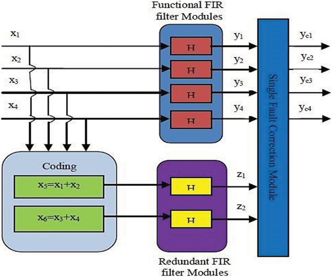
Figure 3: Proposed DMR system
The existing scheme is designed based on the principle of Hamming code. But it is not the real implementation of the Hamming code to correct any single bit of error occurrence in the outputs of the functional filters [20–22]. It can correct the output of a single filter in case it goes in error. The disadvantage of the scheme is that for every four filters; three numbers of redundant filters are to be used increasing the required area on the chip approximately by 75%. The proposed scheme of DMR uses only two redundant filters in addition to the four functional filters with the capability of correcting the output of any one filter at a time it goes in error. For the implementation of the proposed scheme, only 50% extra area is required on the chip as compared to 75% extra area for the existing scheme.
4.1 Functional Fir Filter Modules Block
In this block four identical parallel FIR filters are employed, each having an input x[n] and output y[n]. The outputs of these functional FIR filter modules y1, y2, y3, and y4 are obtained by implementing the subsequent Eqn.
where x[n], y[n], and h[l] are the input signals, output signal, and impulse response of the filter respectively. If the impulse response h[l] is non-zero, the filter is FIR filter, else IIR filter.
In this block, the required inputs for the redundant FIR filter modules are computed from the inputs given to the functional FIR filter modules, as given in
The outputs of the redundant FIR filter modules are implemented.
4.3 Redundant Fir Filter Modules Block
Two redundant FIR filter modules, which are identical to the ones used in the functional FIR filters module, are employed in parallel in this block. The outputs of the redundant FIR filter modules are implemented by the following Eqs. (7) & (8).
This is equivalent to
This is equivalent to
4.4 Single Fault Correction Module
The six outputs y1, y2, y3, y4, z 1, and z2, obtained from these six parallel filters are applied to the single fault correction module which gives the final corrected outputs yc1, yc2, yc3, and yc4 as explained below. The parity code used for the correction of the outputs is generated by the following algorithm.
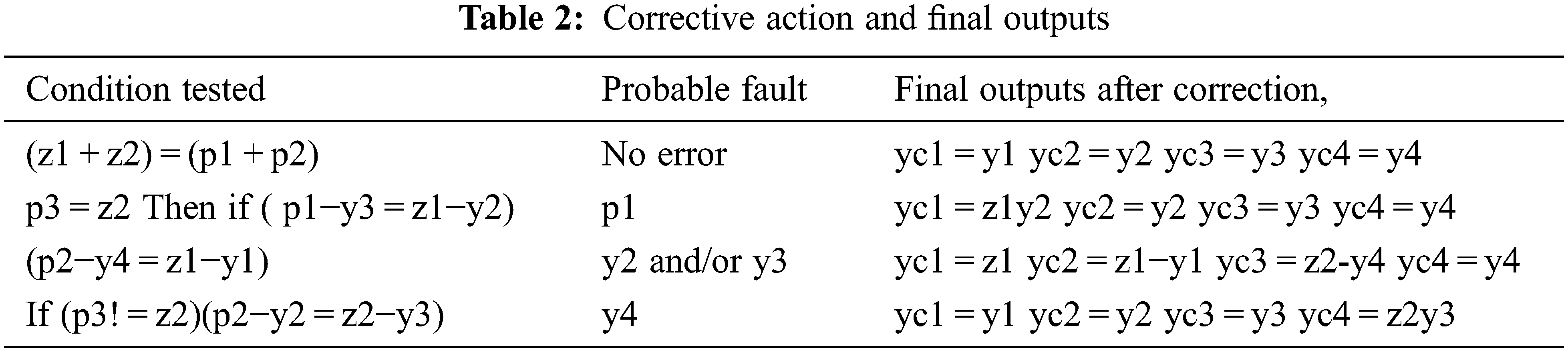
With the assumption that error may occur in the computation of y1, y2, y3, or y4, only one at a time and the redundant filter outputs never go wrong, the following algorithm is developed for correcting the outputs of the functional FIR filter modules one at a time.
No error condition: As z1 contains y1 and y2, z2 contains y3 and y4, testing the condition (z1 + z2 = p1 + p2) confirms that there is no error in the outputs of the any of the functional FIR filter modules and requires no correction.
Correction of error in y1: If (p3 = z2), then the outputs y3 and y4 have no error. Followed by this test, if (p1−y3 = z1−y2) then there is no error in y3 and y2. Then if an error occurs in y1, if any, can be corrected by yc1 = z1−y2.
Correction in y2 and y3: If (p2−y4 = z1−y1), then there is no error in y1 and y4. Then error may lie in y2 and/or y3, if any, and can be corrected as yc2 <= z1y1 and yc3 <= z2−y4.
Correction in y4: If p3! = z2, and p2−y2 = z2−y3, then there is no error in y3. Error, if any, may lie in y4. It can be corrected as yc4 = z2−y3.
The proposed method is advantageous in that it uses only two redundant modules instead of three in the existing method and savings in area on the chip is achieved. The six outputs y1, y2, y3, y4, z 1 and z2, obtained from these six parallel filters are applied to the single fault correction module which gives the final corrected outputs yc1, yc2, yc3 and yc4 as explained is shown in Table 2.
Both the existing and proposed schemes of DMR are implemented in Xilinx ISE 14.7 software in Verilog targeted to Virtex-4, XC4VLX80. All the filter modules are implemented with 4th order and 4-bit sampled inputs. The test bench wave form for the proposed method is shown in Fig. 4. For the simulation, the inputs x1, x2, x3, and x4 are taken as 2, 3, 4, and 5 respectively. The filter coefficients for each filter are taken as 4, 3, 8 and 9. Accordingly the outputs yc1, yc2, yc3 and yc4 are obtained as 48, 72, 96 and 120 respectively.
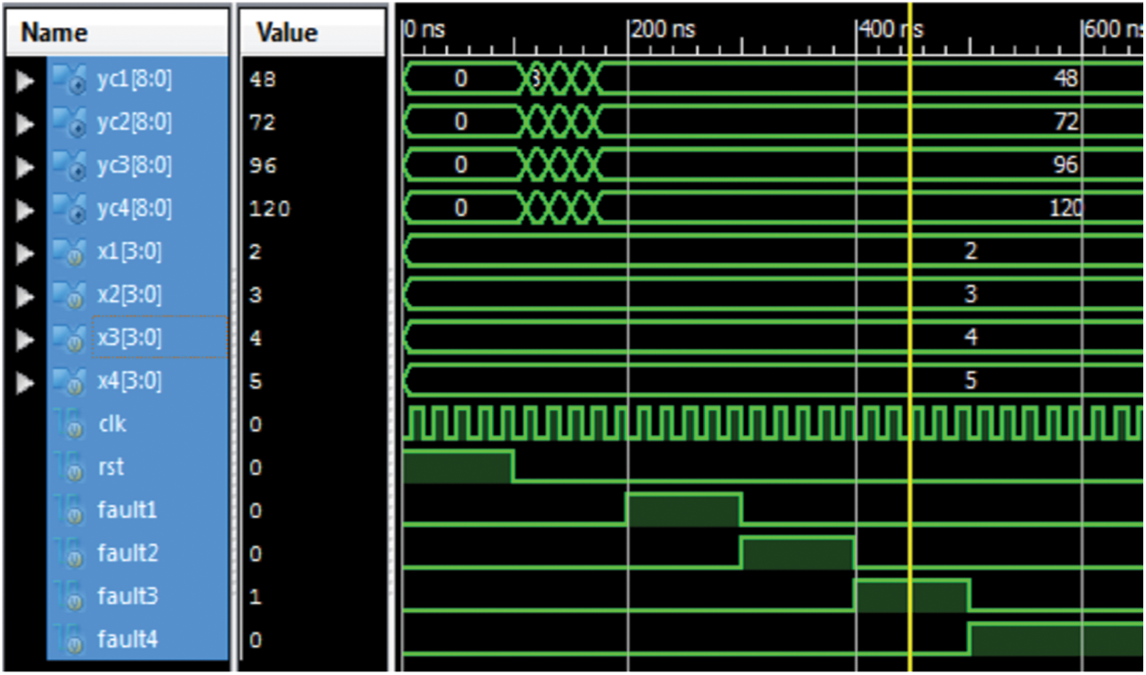
Figure 4: Test bench waveform for the correction module
The test bench waveform for the correction module alone is shown in Figs. 4 & 5. In this waveform, the outputs of all filters in the proposed scheme are given as inputs. They are 48, 72, 96, and 120 respectively. In the first instance no fault is introduced and hence the outputs are same as inputs. In the second instance y1 is given as 49 instead of 48, which is corrected and given as 48 at the output. Accordingly, when inputs with errors are given in the following instances as 76, 97, and 121 respectively, they have been corrected as 72, 96, and 120 respectively and given at the outputs. The total gate count is shown in Fig. 6.
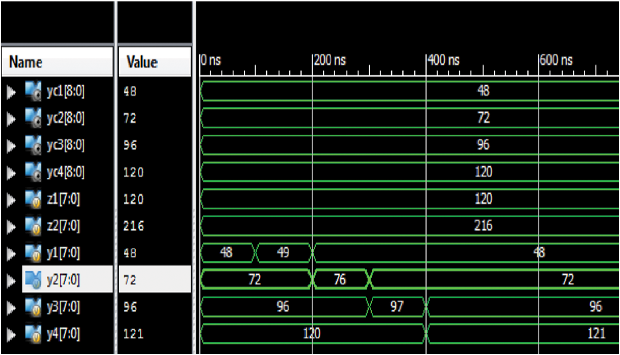
Figure 5: Test bench wave form of the correction module in the proposed scheme
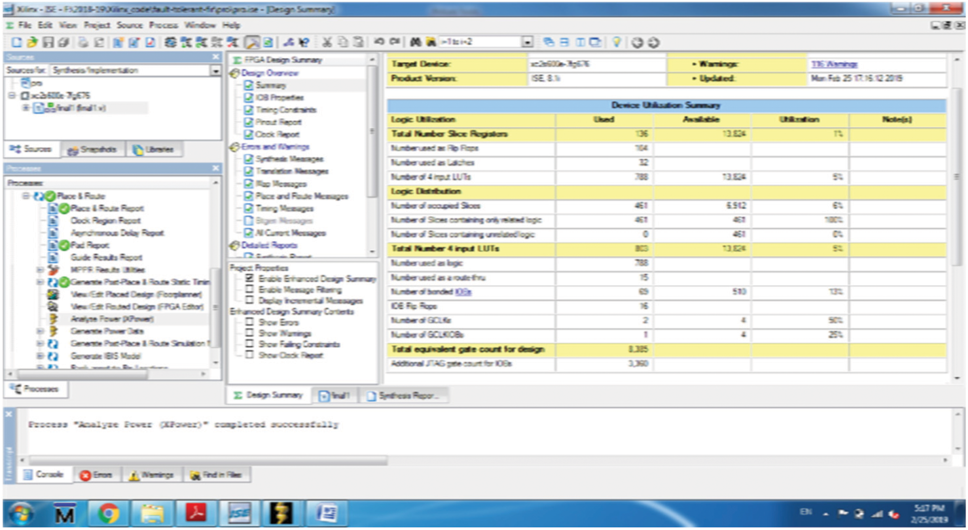
Figure 6: Total equivalent gate count for design proposed system
The Performance analysis of 2W4R and 3W4R memory modules on Virtex-4, XC4VLX80 is illustrated in Figs. 7a and 7b. The chip area (No. of Slices and a input of LUTs), DSP48s, Flip Flops and bonded IOBs parameters are considered concerning different memory depths for performance analysis. The 2W4R memory module utilizes 1.15% of slices, 12% of LUT’s for 8 K memory depth, 2.27% of slices, 29% of LUT’s for 16 K storage depth. In comparison to, the 3W4R storage unit utilizes 1.165% of slices, 20% of LUT’s for 8 K memory depth, 2.28% of slices, and 36% of LUT’s for 16 K memory depth.
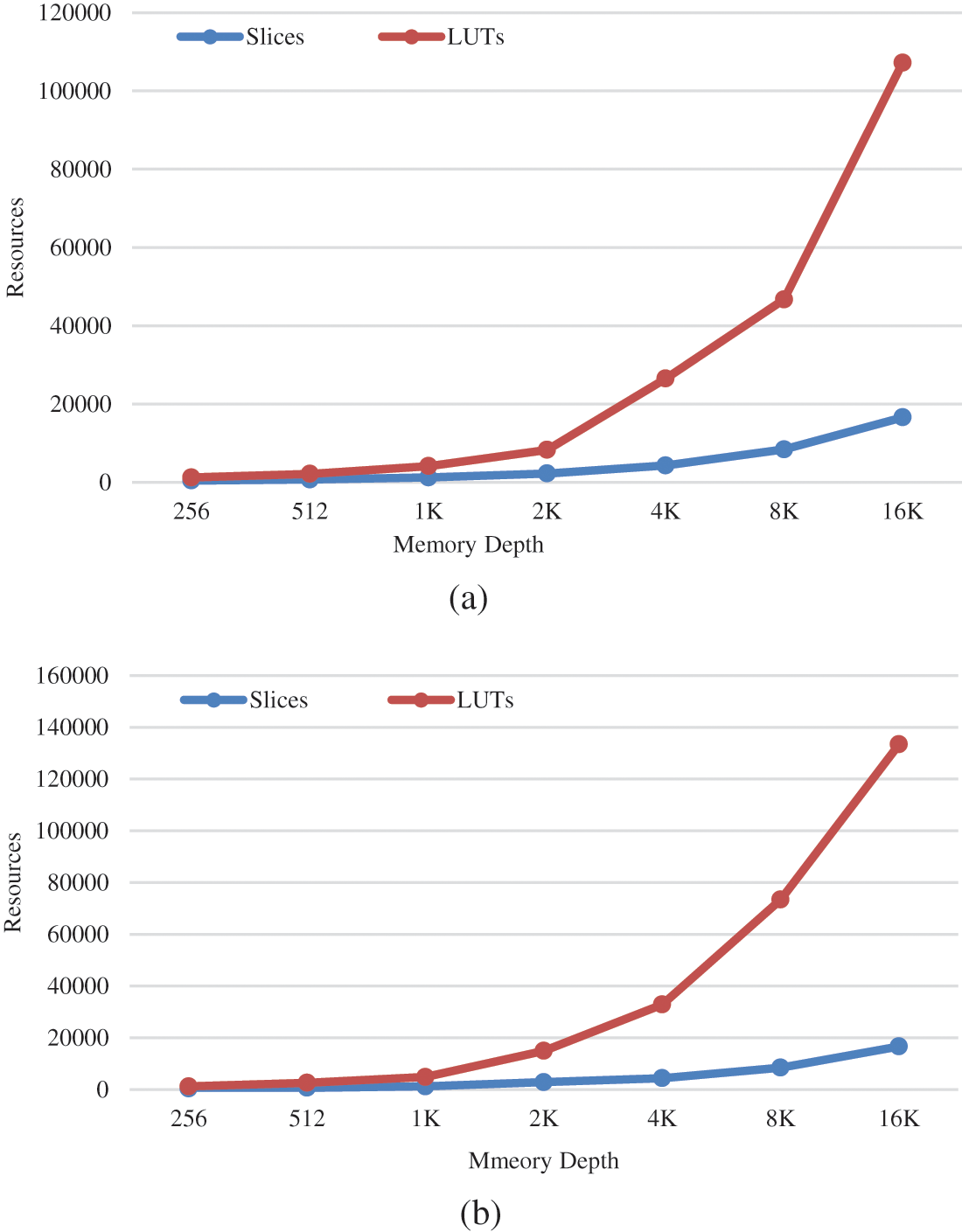
Figure 7: Area v/s memory depth (a) 2W4R (b) 3W4R
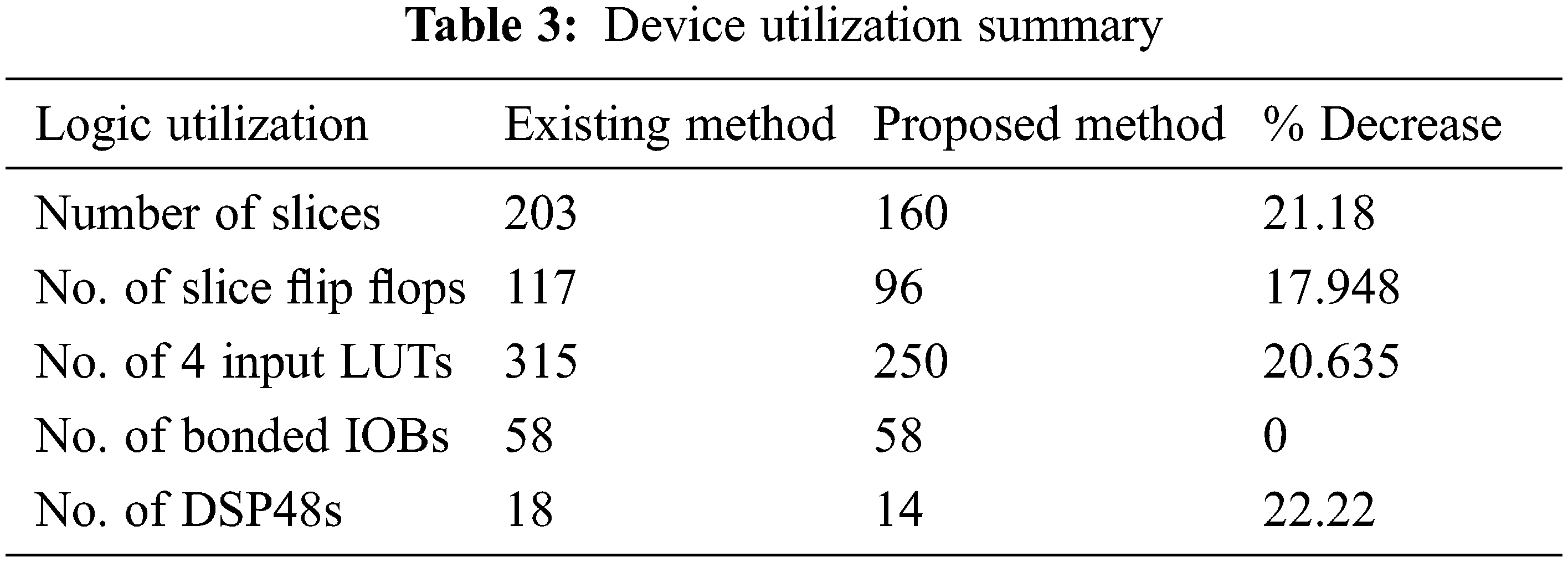
The device utilization of the proposed DMR is summary is shown in Table 3. When comparing the suggested technique to the present way, the device utilization summary shows that the proposed method reduces the area by 21.18 percent. In the first instance, no fault is introduced and hence the outputs are the same as the inputs. In the second instance, y1 is given as 49 instead of 48, which is corrected and given as 48 at the output. The filter coefficients for each filter are taken as 4, 3, 8, and 9. Accordingly, the outputs yc1, yc2, yc3 and yc4 are obtained as 48, 72, 96 and 120 respectively.
The performance summary is given below. As both the existing and proposed schemes are parallel implementations of the same filters, no change in the delay/speed is observed.
Minimum period: 0.582 ns
Maximum Frequency: 1717.475 MHz
Minimum input arrival time before clock: 7.449 ns
Maximum output required time after clock 3.879 ns
First, the three approaches are tested against the conventional grayscale pictures displayed in Fig. 8, and the uncorrupted median filtered images are saved for further comparisons. Then the fault-tolerant FIR filter is executed for error detection methods with standard test images using the Xilinx ISE 14.7 software in Verilog targeted to Virtex-4, XC4VLX80. In short, the reports from our proposed method illustrate that approximately 91% of the corrupted images are detected with our implementation.

Figure 8: Standard test images
The fault-tolerant parallel filter system is implemented in Xilinx ISE 14.7 found to have given a significant reduction in the area which reduces the cost of implementation. This approach is expanded in this short to display how parallel FIR filters could be kept using ECCs in which each individual filter is comparable to a bit in a standard ECC for image denoising applications. The proposed method of DMR is advantageous in that it uses only two redundant modules instead of three in the existing method and savings in the area on the chip are achieved. Faults were introduced in all the outputs of the functional filters and found that the fault in every output is corrected. The filters are implemented for four-bit inputs in fourth-order. Further work in this direction can be done to implement higher-order filters with efficient methods to further reduce area, performance, and power so that they find good practical applications.
Acknowledgement: The authors with a deep sense of gratitude would thank the supervisor for his guidance and constant support rendered during this research.
Funding Statement: The authors received no specific funding for this study.
Conflicts of Interest: The authors declare that they have no conflicts of interest to report regarding the present study.
References
1. C. Cheng and K. K. Parhi, “Hardware efficient fast parallel FIR filter structures based on iterated short convolution,” IEEE Transactions on Circuits and Systems I: Regular Papers, vol. 51, no. 8, pp. 1492–1500, 2004. [Google Scholar]
2. A. Chandra and S. Chattopadhyay, “Design of hardware efficient FIR filter: A review of the state-of-the-art approaches,” Engineering Science and Technology, an International Journal, vol. 19, no. 1, pp. 212–226, 2016. [Google Scholar]
3. N. Hindman, “Fully automated radiation hardened by design circuit construction,” Ph.D. Dissertation, Arizona State University, 2012. [Google Scholar]
4. S. Dutta, Z. Bai, T. M. Low and P. Grover, “CodeNet: Training large scale neural networks in presence of soft-errors,” arXiv preprint arXiv:1903.01042, 2019. [Google Scholar]
5. T. J. O’Gorman, “The effect of cosmic rays on the soft error rate of a DRAM at ground level,” IEEE Transactions on Electron Devices, vol. 41, no. 4, pp. 553–557, 1994. [Google Scholar]
6. S. Kulis, “Single event effects mitigation with TMRG tool,” Journal of Instrumentation, vol. 12, no. 1, pp. C01082, 2017. [Google Scholar]
7. K. Pravalika and C. R. Prasad, “Fault-tolerant parallel filters based on ECC codes,” Advances in Computational Sciences and Technology, vol. 11, no. 7, pp. 597–605, 2018. [Google Scholar]
8. O. Boncalo, A. Amaricai and Z. Lendek, “Fault tolerant digital data-path design via control feedback loops,” Electronics, vol. 9, no. 10, pp. 1721, 2020. [Google Scholar]
9. K. R. Vaddempudi, M. Tech, F. SMIEEE and M. PMACM, “An area efficient fault tolerant parallel FIR filter design,” Journal of Advanced Research in Dynamical and Control Systems, vol. 9, no. 3, pp, 1–6, 2017. [Google Scholar]
10. B. Shim and N. R. Shanbhag, “Energy-efficient soft error-tolerant digital signal processing,” IEEE Transactions on Very Large Scale Integration (VLSI) Systems, vol. 14, no. 4, pp. 336–348, 2006. [Google Scholar]
11. P. Reviriego, S. Pontarelli, C. J. Bleakley and J. A. Maestro, “Area efficient concurrent error detection and correction for parallel filters,” Electronics Letters, vol. 48, no. 20, pp. 1258–1260, 2012. [Google Scholar]
12. Z. Gao, P. Reviriego, W. Pan, Z. Xu, M. Zhao et al., “Fault tolerant parallel filters based on error correction codes,” IEEE Transactions on Very Large-Scale Integration (VLSI) Systems, vol. 23, no. 2, pp. 384–387, 2014. [Google Scholar]
13. M. B. Trimale, A review: FIR filter implementation. In 2nd IEEE International Conference on Recent Trends in Electronics, Information & Communication Technology (RTEICT), pp. 137–141, 2017. [Google Scholar]
14. V. S. Vaisakhi, D. Surendran and T. Prabu, “Fault tolerance in a hardware efficient parallel FIR filter,” in Proc. 2018 Int. Conf. on Current Trends Towards Converging Technologies (ICCTCT), Coimbatore, India, pp. 1–4, 2018. [Google Scholar]
15. X. Ma, Y. Lu, Y. Lu, Z. Pei and J. Liu, “Biomedical event extraction using a new error detection learning approach based on neural network,” Computers, Materials & Continua, vol. 63, no. 2, pp. 923–941, 2020. [Google Scholar]
16. A. Arunadevi, K. Chitra, S. GunaNandhini, T. Raghupathi and M. Rejusha, “A review on area efficient parallel FIR digital filter implementation,” SSRG International Journal of VLSI & Signal Processing, vol. 2, no. 2, pp. 1–5, 2015. [Google Scholar]
17. A. Appathurai, G. Manogaran and N. Chilamkurti, “Trusted FPGA-based transport traffic injects, impersonate (I 2) attacks beaconing in the internet of vehicles,” IET Networks, vol. 8, no. 3, pp. 169–178, 2019. [Google Scholar]
18. L. K. Phimu and M. Kumar, “Vlsi implementation of area efficient 2-parallel Fir digital filter,” International Journal of VLSI Design & Communication Systems (VLSICS), vol. 7, no. 5, pp. 1–8, 2016. [Google Scholar]
19. A. Zaka, R. Jabeen and K. I. Khan, “Error detection and pattern prediction through phase ii process monitoring,” CMC-Computers Materials & Continua, vol. 70, no. 3, pp. 4781–4802, 2022. [Google Scholar]
20. A. Appathurai and P. Deepa, “Design for reliablity: A novel counter matrix code for FPGA based quality applications,” in Proc.6th Asia Symp. on Quality Electronic Design (ASQED), Kula Lumpur, Malaysia, pp. 56–61, 2015. [Google Scholar]
21. X. R. Zhang, X. Chen, W. Sun and X. Z. He, “Vehicle re-identification model based on optimized DenseNet121 with joint loss,” Computers, Materials & Continua, vol. 67, no. 3, pp. 3933–3948, 2021. [Google Scholar]
22. X. R. Zhang, H. L. Wu, W. Sun, A. G. Song and S. K. Jha, “A fast and accurate vascular tissue simulation model based on point primitive method,” Intelligent Automation & Soft Computing, vol. 27, no. 3, pp. 873–889, 2021. [Google Scholar]
Cite This Article
 Copyright © 2023 The Author(s). Published by Tech Science Press.
This work is licensed under a Creative Commons Attribution 4.0 International License , which permits unrestricted use, distribution, and reproduction in any medium, provided the original work is properly cited.
 Downloads
 Citation Tools