
 Submit a Paper
 Propose a Special lssue
 Open Access
ARTICLE

Simulation and Experimental Design of Load Adaptive Braking System on Two Wheeler
Department of Automobile Engineering, Sri Venkateswara College of Engineering, Sriperumbudur, Pennalur, 602117, India
* Corresponding Author: Ramanjaneyulu Kolla. Email:
Computer Systems Science and Engineering 2023, 45(3), 3115-3134. https://doi.org/10.32604/csse.2023.033077
Received 07 June 2022; Accepted 12 July 2022; Issue published 21 December 2022
 View Full Text
 Download PDF
Abstract
The braking quality is considered the main execution of the adaptive control framework that impacts the vehicle safety and rides solace astoundingly notably the stopping distance. This research work aims to create a pattern and design of an electromechanically adjusted lever that multiplies the applied braking force depending on the inputs given by the sensors to reduce the stopping distance of the vehicle. It is carried out using two main parts of the two-wheeler vehicle: the first part deals with the detection of load acting on the vehicle and identifying the required braking force to be applied, and the second part deals with the microcontroller which activates the stepper motor for varying the mechanical leverage ratio from various loads on the vehicle using two actively movable wedges. The electromechanically operated variable braking force system is developed to actuate the braking system based on the load on the motorcycle. The MATLAB simulation and experimental work are carried out for various loading (driver and pillion) conditions on a two-wheeler. The results indicate that the proposed electronically operated braking system is more effective than the conventional braking system for various loads and vehicle speeds. Specifically, the stopping distance of the vehicle is decreased significantly by about 4.9% between the conventional braking system and the simulated proposed system. Further, the experimental results show that the stopping distance is condensed by about 4.1%. The validation between simulated and experimental results revealed a great deal with the least error percentage of about 0.8%.Keywords
Ride comfort is a significant element in the design of two-wheeler vehicles and intelligent transportation frameworks. Simultaneously, ride comfort is impacted by different variables, for instance, vibration, sound, temperature, visual stimuli, and vehicle assembly plan. An incredible number of examination studies have been directed to further developing ride comfort, especially in the field concerning ride awkward inclination brought about by vertical vibration, and a lot of dynamic and latent suspension control calculations were advanced to further develop the vertical vibration [1,2]. Notwithstanding, the inconvenience feeling isn’t just gotten from the vertical vibration, however, it is additionally brought about by measure of vehicle speed increase and jerk in the longitudinal direction, which is how much change in vehicle speed increases [3–5]. This present circumstance is exceptionally normal when the vehicle is speeding up or decelerating. Regardless, there is still little exploration regarding this matter [6,7]. Along these lines, we are just concerned about one of the elements that affected ride comfort, which is connected with vehicle longitudinal dynamics. Meanwhile, with the improvement of electronic control innovation, the kind of brake framework is additionally evolving [8,9]. Among the many schemes, Load adaptive brake system is an intelligent system which adjusts its braking according to the driving situation.
The reason for a vehicle brake framework is to control the speed of the vehicle in a protected way. Security requires the accomplishment of both a generally short halting distance and directional control during heavy braking. In the past, it has been the driver who needed to track down this equilibrium. Intelligent braking frameworks can now help the driver. Progressed frameworks can start and deal with the braking occasion. Blend vehicles can have different brake control advances on the various parts and this can bring about less than ideal execution, in any event, when one section has an intelligent brake framework. The similarity of brake innovations is significant. Based on the needs, a robust literature survey is carried out for intelligent braking systems and illustrated in Table 1.

Generally, in a two-wheeler, balancing the vehicle is quite more difficult than in a four-wheeler. This is the reason which may lead to the increasing accidents are very high when compared with four-wheeler vehicle accidents [19]. Basically, when designing any conventional mechanical braking system, it is used to consider two parameters i.e., one is speed, and another one is a load. In the conventional mechanical braking system, it is used to design the disc brake for variable speed with a fixed load. But in real-time, when the vehicle comes to the on-road condition, it may vary both speeds, as well as load, which may increase the stopping distance of two-wheeler vehicles [20] when compared with a four-wheeler. During sudden braking in a two-wheeled vehicle, the normal dynamic reaction forces are varied between the tire surface and road, due to the vehicle load transfer effect from the rear side to the front of the vehicle when the less pillion load is available in the vehicle [21]. So, researchers developed the interconnected mathematical model to compute normal load carrying at each tire and built it into a high fidelity vehicle model [22]. Brake pressure force was spread according to the predicted load. Simulations were conducted using the mathematical model to inspect normal dynamic reactions under different load conditions. To minimize the accidents, the lowest amount of stopping distance must be achieved. It is consummate with the help of maximum deceleration of the vehicle. This highest deceleration of the vehicle depends on the highest braking force [23]. If applying braking force exceeds the maximum frictional force limit between tire and ground surface in a vehicle slipping will occur due to the locking of wheels. Hence an optimum braking force [24,25] helps to attain the least possible stopping distance without slipping the vehicle wheels. In the conventional or normal braking system in a vehicle, there is no additional system included to achieve the least stopping distance for different drivers and pillion load. This may be the reason for increasing the number of accidents in a two-wheeler.
Based on the inferences from existing works and gaps, this work focus to attain the following objectives:
– To create a pattern and design of electromechanically adjusted lever that multiplies the applied braking force depending on the inputs given by the sensors.
– To detect the Load acting on the vehicle and to identify the required braking forces to be applied.
– To propose a microcontroller-based novel framework that activates the stepper motor for varying the mechanical leverage ratio from the various loads on the vehicle.
– To minimize the stopping distance using a powered leverage ratio framework.
– To validate the proposed model with simulation and experimental work against various load conditions in a two-wheeler.
The rest of the article is structured as follows: Section 2 presents the modelling of the system; Section 3 describes the proposed methodology adapted for this work; Section 4 demonstrates a detailed simulation study to find the vehicle parameters; Section 4 illustrates the fabrication of the proposed desogn and results: Section 6 concludes the article based on the observed outcome form the proposed scheme.
During the static load condition, a motorcycle’s front-wheel axle load distribution is measured by using the digital weighing machine. After finding out the front wheel axle load distribution in the vehicle, the relevant moment about the rear axle wheel is taken to compute the motorcycle center of gravity (CG) in a horizontal location. Fig. 1 shows measured the wheel axle load distribution in static conditions by using a digital weighing scale. To measure the motorcycle CG in the vertical position rear wheel of the vehicle is lifted to a minimum height and observes the weight distribution on the front wheel axle by using the digital weighing machine a formula is given in an Eq. (1) is used to calculate the CG in the vertical position of the motorcycle. Fig. 2 shows measured the CG in the horizontal and vertical positions in a two-wheeler. Table 2 shows measured the motorcycle axle loads acting on the front wheel axle and rear wheel axle when it is on a flat surface and the rear wheel is lifted for various pillion load conditions. Table 3 shows measured the motorcycle horizontal and vertical locations of the CG.
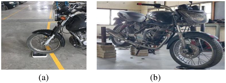
Figure 1: (a) Axle load is measured by using the weighing scale (b) Lifted rear wheel to find the vertical digital location of CG
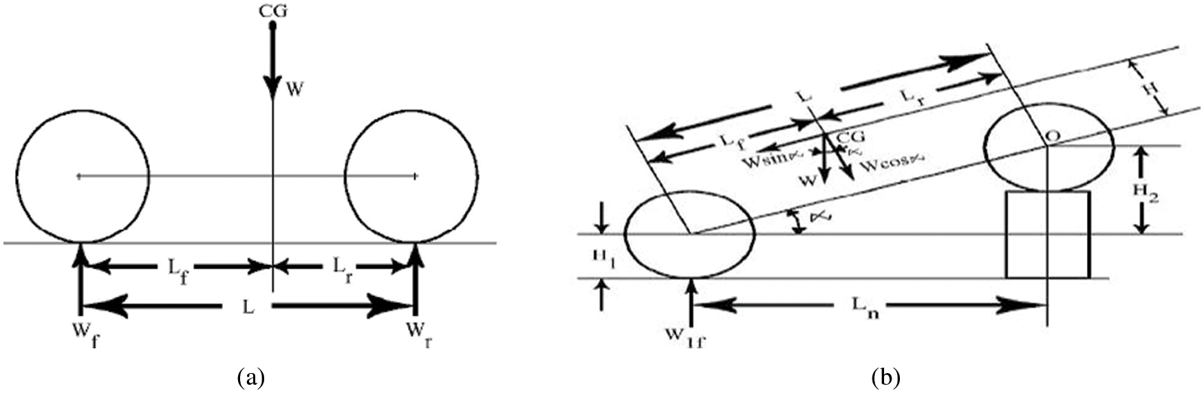
Figure 2: (a) Motorcycle weight distribution in level (b) Motorcycle weight distribution when the rear wheel is lifted


Height of CG from the ground level
where, Wf = Motorcycle front axle weight when it is on a level surface; Wr = Motorcycle rear axle weight when it is on a level surface; Wlf = Motorcycle front axle weight when rear-wheel lifted from the ground surface; Wt = Motorcycle total gross weight = Wf + Wr; W2f = Motorcycle front axle weight is added when rear-wheel lifted = Wlf−Wf; L = Motorcycle wheelbase length when it is on level surface = 1330 mm; H1 = Motorcycle front hub height from the ground surface = 300 mm; H2 = Motorcycle vehicle rear wheel hub height is over the static front wheel hub; Ln = Motorcycle new wheelbase length when the rear wheel is lifted.
2.2 Motorcycle Braking Dynamics
Motorcycle axle load in static condition:
When the motorcycle is in static condition or running with a constant velocity on a flat surface and the various reaction forces are measured with the help of the digital weighing machine are the same has been illustrated in Fig. 3. The load acting on the vehicle is distributed from the front axle to the rear axle. Therefore the static axle load performing on the vehicle is changing in the front axle and rear axle. Motor cycle load distribution in the static axle condition is rear axle load in static to the whole motorcycle weight, designated with small Greek letters; a formula is given in an Eq. (2).
where,
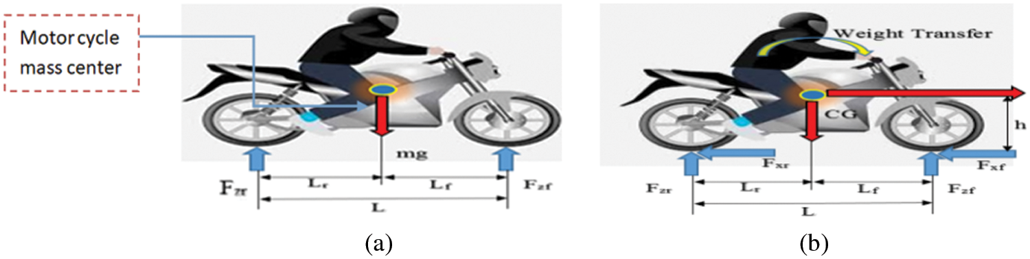
Figure 3: Axle load (a) Static condition (b) Dynamic condition and load transfer effect during braking
The relative axle load in a static condition at the front wheel is given by
where
During no-load conditions vehicle value is as high as 0.59, representing that only 59% of the motorcycle weight is handled by the rear axle. These results show that when the vehicle has less load at the static rear wheel one of the mainly significant issues is mechanical brake balance analysis to avoid early rear brake confine is required.
Motorcycle axle load in dynamic condition:
When the brakes have been used in vehicles in dynamic conditions, the torque produced by the brake is resisted by the circumference of the tire where it makes contact with the ground surface. Earlier brake lockup, the amount of the braking forces is a direct utility of the torque produced by the brake. For the hydraulic operation of the brakes, Eq. (4) is used to influence the actual braking forces in dynamic conditions.
where; Fx = Total braking force N;
r = Effective disc radius; R = Tyre radius (300 mm).
The motorcycle is decelerating on a flat road surface when the brakes are applied, at the moment develops various forces, and the load transfer effect on a two-axle vehicle is illustrated in Fig. 3. Apply the moment balancing Eq. (5) at the rear tire to the ground surface to find the front axle’s normal dynamic force.
Similarly, apply the moment balancing Eq. (6) at the front tire to the ground surface to find the rear axle’s normal dynamic force.
Examine the Eqs. (5) and (6), the results show that the normal axle forces in the dynamic condition are linear to deceleration ‘a’, i.e., straight-line relations. During sudden braking, the amount of load transfer effect of the rear axle in the dynamic condition is given by the terms χaW in Eqs. (5) and (6). The normal front axle and rear axle load of a typical motorcycle are illustrated in Figs. 4 and 5 for the empty, driver-only, and additional every 10 kg cases, considering driver weight (50 kg) is constant. The theoretical value shows that dynamic axle loads, that the front axle load is significantly higher at higher decelerations than that associated with the rear axle. For example, the static front axle load has increased drastically from 854 N to 1618 N for a 1 g, but the rear axle load has decreased in static load condition from 1039 N to only 275 N for a 1 g stop.
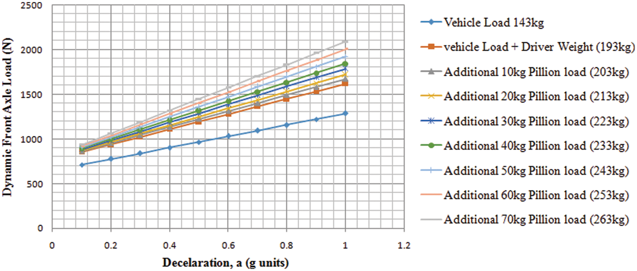
Figure 4: Dynamic front axle loads for constant driver load of 50 kg and various pillion loads
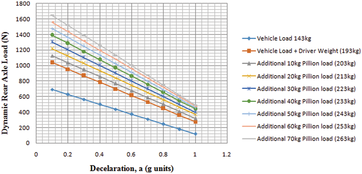
Figure 5: Dynamic rear axle loads for constant driver load of 50 kg and various pillion loads
In general, the hydraulic operated braking system is designed, first concentrating the force developing in the braking system and the corresponding movement of the frictional brake pads. If sufficient pressure is developed in the braking system, then pads are moved smoothly axially against the disc rotation inducing the kinetic energy. The required braking force and braking torque are calculated using the mathematical Eqs. (7) and (8) for different pillion loads on the vehicle and the results are shown in Fig. 6.
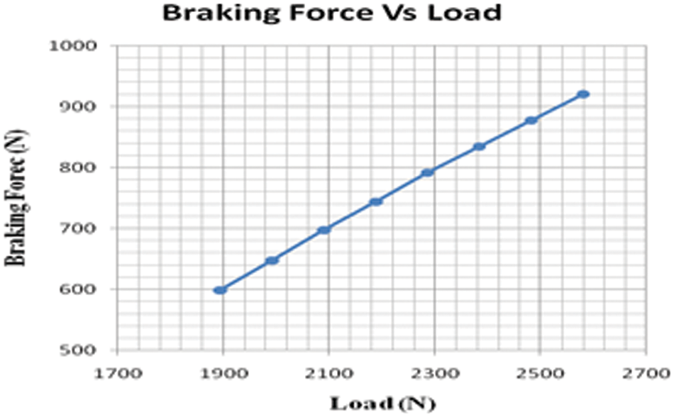
Figure 6: Braking force vs. load
Case 1: Driver and the vehicle weight = 193 kg
where, Ft = Braking force at tyre, N; Tt = Braking torque at tyre, N; Lf = Distance of C.G from front wheel; L = Wheel base = 1300 mm; Rt = Radius of the tyre = 223.6 mm; μ = coefficient of friction = 0.7.
The above Eq. (7) is used to calculate the braking force at different loading conditions in Table 4.

A load adaptive braking force system is planned designed and applied to the rear axle of a motorcycle to develop the maximum braking force between the tire and the ground surface and reduce the stopping distance of the motorcycle and thereby, improving the safety of the rider. In the existing braking system, the pressure develops in the master cylinder and the mechanical leverage ratio is kept constant. Hence the efficiency of the braking system was poor when the motorcycle weight gets changed. Therefore, to improve the existing braking system a load adaptive braking force system is suggested in the present work. In this system the pressure develops in the master cylinder varies by adjusting the mechanical leverage ratio of the brake pedal based on the pillion load on a motorcycle during the static condition. Hence the maximum brake force developed between the ground surface and the tire is controlled based on the pillion load on a motorcycle. A typical motorcycle is selected to implement the load adaptive braking system. An optimum leverage ratio will be determined based on the various pillion load and vehicle geometry of the typical motorcycle, keeping the effective disc radius and the rider weight constant. To change the leverage ratio a stepper motor is used to move to the position of the pivot pin. Whenever the load on the motorcycle is changed, the microcontroller will send a signal to the stepper motor to vary the position of the pivot pin of the brake pedal to change the magnitude of hydraulic brake line pressure, when the motorcycle is in static condition as shown in Fig. 7. Also, brake fluid reservoir supplies an optimum amount of fluid through master cylinder and non-return valve based on the movement of push rod. It is also revealed that the optimum braking force is a function of the vehicle geometry and pillion load on the motorcycle.
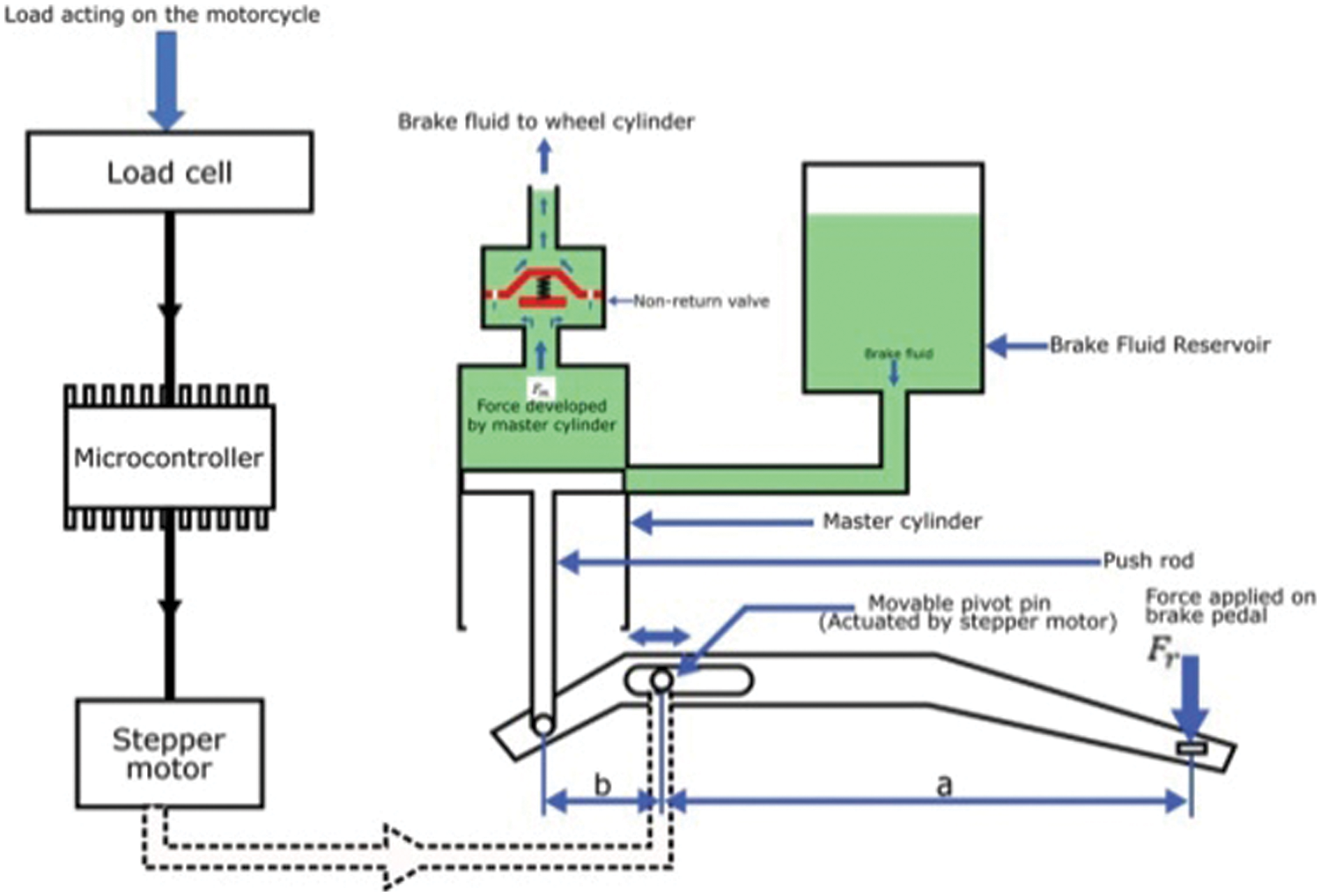
Figure 7: Schematic diagram of the load adaptive braking system
Taking moment balance with respect to the fulcrum point i.e., pivot pin
where, Fr–Force applied at brake pedal by the rider; Fm–Force develops at the master cylinder; a–Distance between the line of action of force applied at brake pedal to pivot pin; b–Distance between the line of action of force develops at the master cylinder to pivot pin; a/b–Mechanical leverage ratio
Table 5 shows that the same Lr value obtained for the different braking forces applied at the pedal indicates that the pivot point in the pedal is fixed. It also shows that in the case of the load from 193 to 263 kg is varied, the pressure rises in the caliper and also in the brake line. If the pressure raises in the caliper exceeds the critical pressure, wheel locking happens and skidding occurs.

The above problem is overcome by the implementation of the variable leverage ratio mechanism in the existing braking system. The same braking force is obtained by changing the Lr value by applying minimum pedal force at all load conditions.
Case 1: Breaking force at 193 Kg
Apply Newton’s second law in the existing braking system to calculate the deceleration and stopping distance of the motorcycle for various loads and vehicle velocity using the mathematical Eqs. (11) and (12) and the results are tabulated in Tables 6 and 7.
where, V = velocity of the vehicle m/s; S = stopping distance m; a = Deceleration of the vehicle m/s


3.3 Variable Leverage Ratio Calculation
The area of the master cylinder and the area of the caliper is kept constant to maintain the critical pressure in the master cylinder. So to obtain the same braking force the Lp is varied.
Case1: Driver and the vehicle weight = 193 kg
The required leverage ratio is calculated by using the mathematical Eq. (13) for different rider and pillion loads.
where,
Ft = Braking force in N; Fp = Force applied on the pedal = 392.4 N; Ac = Area of the calliper = 803.84 mm2; Amc = Area of the master cylinder = 226.8 mm2; R = Radius of the tire = 223.6 mm; r = Radius of the disc = 65 mm; μ = Coefficient of friction between the brake pad and disc = 0.35.
Table 7 shows the different load and braking forces and the corresponding position of a pivot point in the brake pedal also results in reveals that the braking force and leverage ratio are linear in Fig. 8.

Figure 8: Braking forces with a leverage ratio
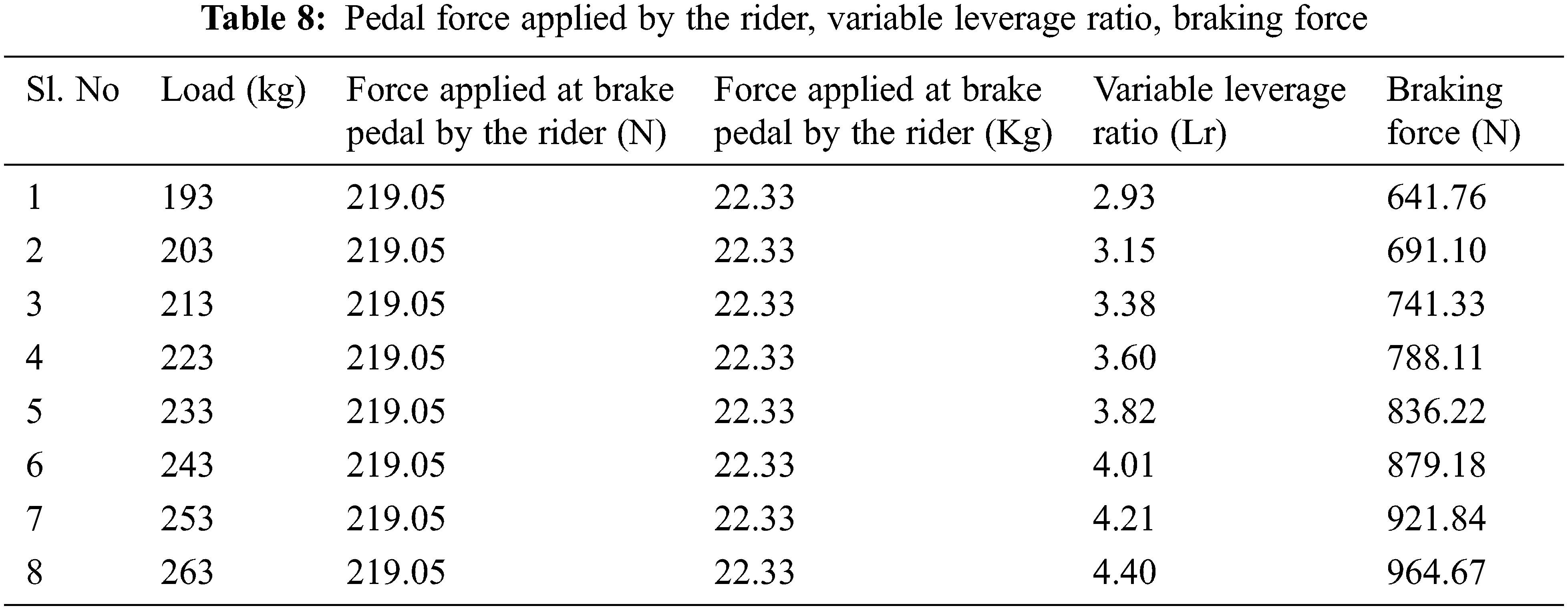
Table 8 shows the optimum braking force produced in the braking system by changing the position of the brake pedal leverage ratio and with minimum pedal force by the rider in all the load conditions concerning different loads. The results show that the minimum braking pedal force by the rider is sufficient to stop the vehicle.
4 Simulation for Finding Vehicle Parameters
In this Simulation, vehicle deceleration, stopping distance, and variable leverage ratio are calculated using the Simulink model as shown in Fig. 9. The vehicle is mostly used to design for moving forward direction or backward direction alongside its longitudinal axis. To analyze the entire vehicle using Simulink in MATLAB and select the Longitudinal Vehicle Dynamics block model a two-axle vehicle, with two similarly sized wheels. The set of Simulink input signals at front dynamic braking force and rear dynamic braking force
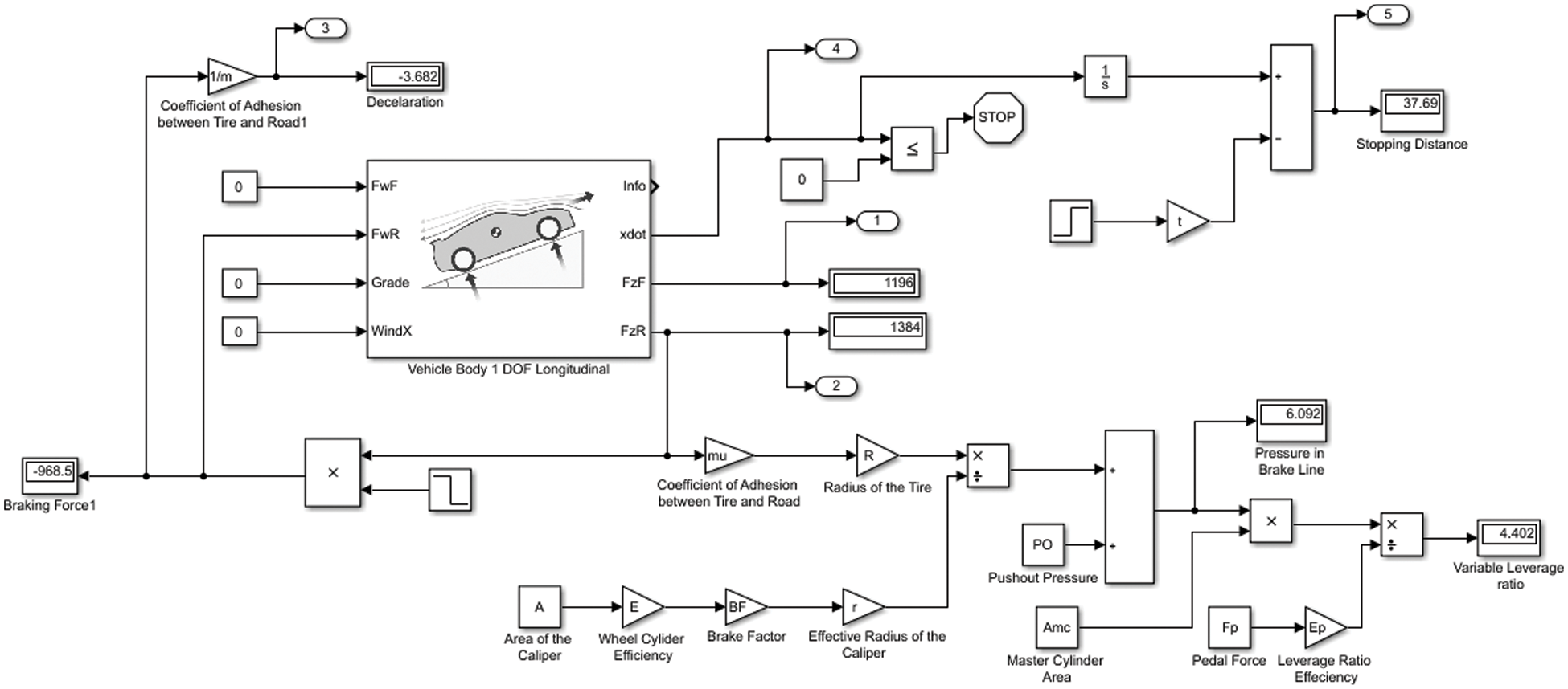
Figure 9: Simulink model for finding deceleration, velocity, and stopping distance vs. simulation time and variable leverage ratio
The output
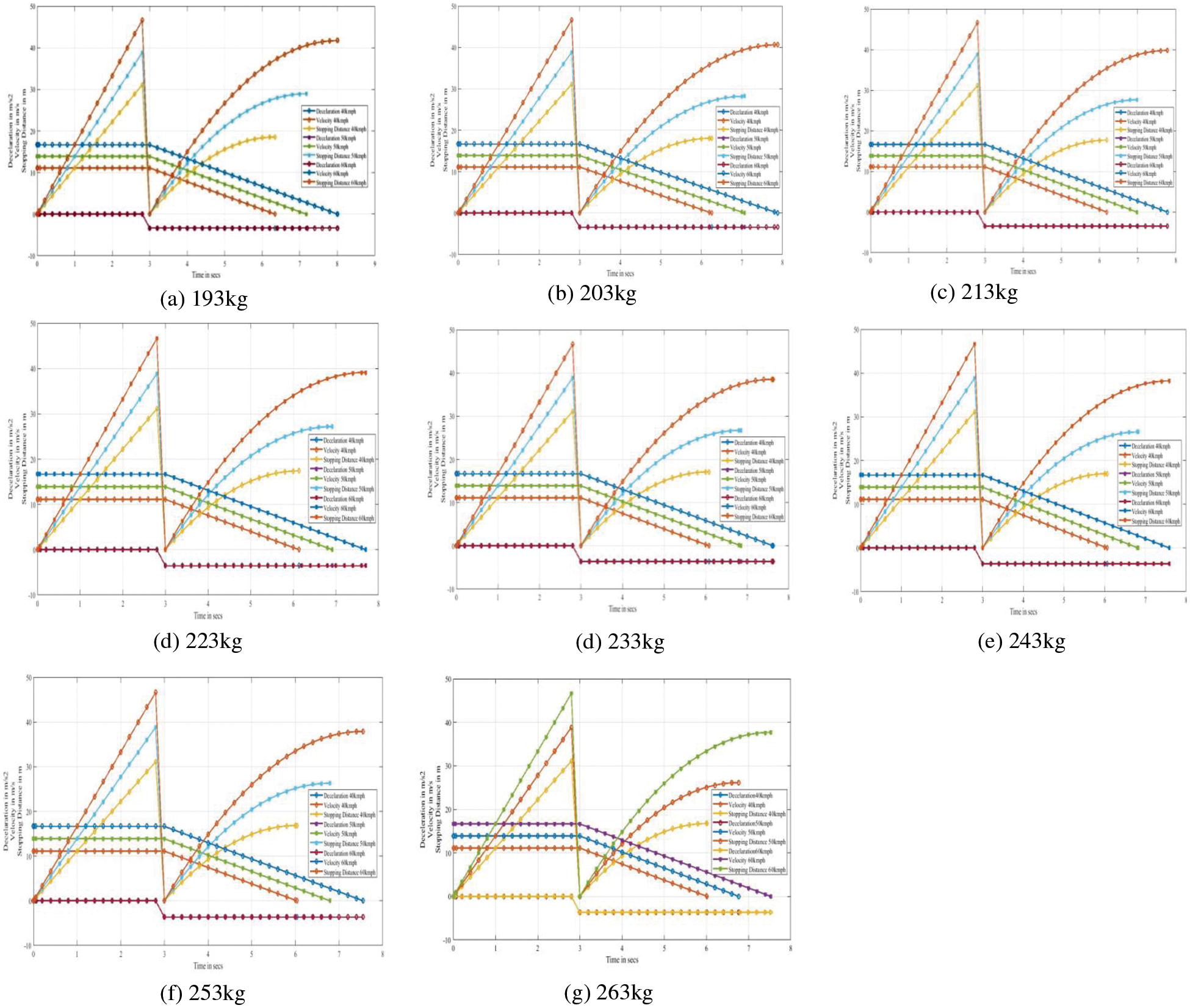
Figure 10: Changes during braking
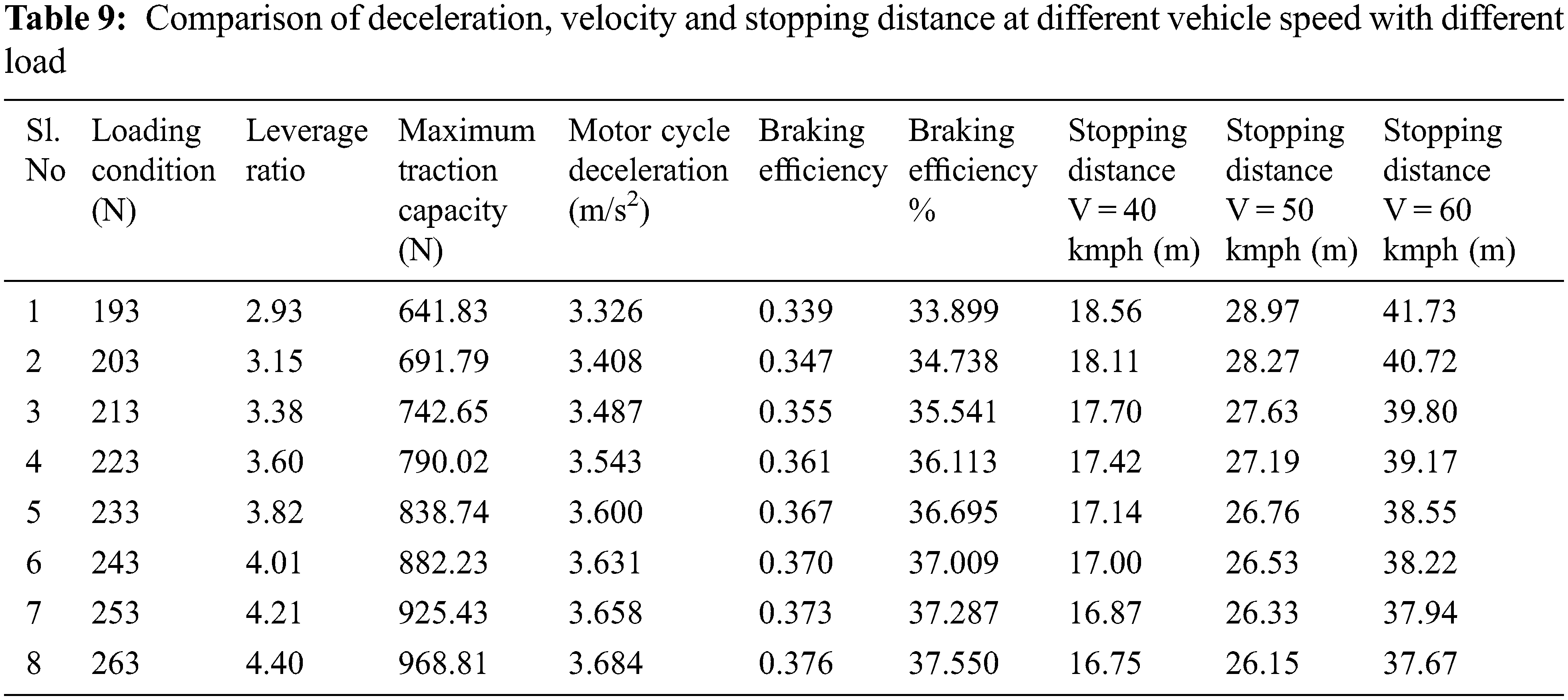
Fig. 10 show that the stopping distance of the motorcycle depends on the vehicle’s speed. When the speed of the vehicle changes from 40, 50 and 60 kmph then the motorcycle stopping distances were also changed. But, the mechanical leverage ratio and vehicle deceleration won’t depend on the speed of the vehicle. When the load of the motorcycle vehicle varies from 193 to 263 kg, the mechanical leverage ratio and vehicle deceleration were changed. Table 9 shows the optimum braking force produced in the braking system for all the load conditions, considerably by changing the mechanical leverage ratio in the brake pedal. The results show that even though the vehicle load varies from 193 to 263 kg proportional amount of stopping distance of the vehicle is reduced significantly when the adaptive braking system was used.
The stepper motor needs to perform a unique action as it should move the brake pedal pivot point in both directions i.e., the forward and backward direction along the X-axis to the position of the vehicle. However, a normal stepper motor offers a rotation movement only in its shaft axis. Therefore, a novel mechanism is required to convert the rotational movement of the motor to the linear movement of the brake pedal pivot point. Consequently, a simple thread and nut mechanism is used to convert the rotational movement to linear. The motor output shaft is connected to the thread, nut having with similar pitch, and size is attached to the pivot point. Henceforth, the rotation movement of the thread is converted into linear of the pivot point by fixing the stepper motor case with the vehicle frame (Fig. 11).
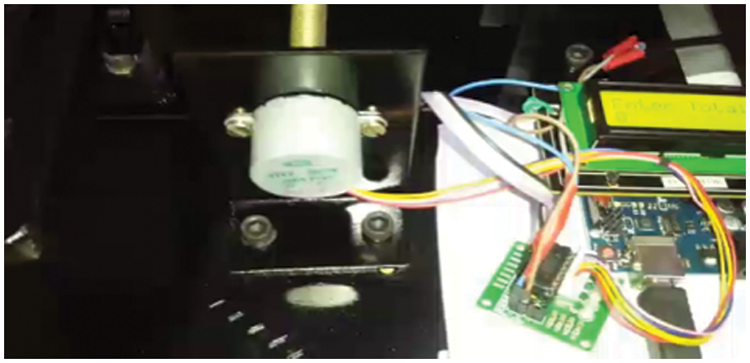
Figure 11: Stepper motor
The foremost mechanisms adapted in the hydraulic braking system are the master cylinder and piston. They are a significant element of the hydraulic braking system, which starts and controls the action of the braking force. Additionally, a reservoir is attached at the bottom of the master cylinder, which is used to store the brake fluid. Then the brake pedal actuates the master cylinder to generate the necessary braking force for the vehicle until halts (Fig. 12).
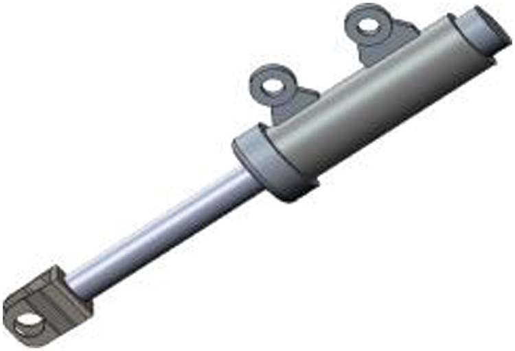
Figure 12: Master cylinder
The brake pedal is a foot pedal that moves the piston in the brake master cylinder. Depending on the mechanical lever ratio and the input force applied by the rider, the incompressible brake fluid applies a greater force to the brake pads against the rotational movement of the disc. The material used in the fabrication of the brake pedal is mild steel. It is used primarily because of its availability and the ease of machining. The slot is machined using a vertical milling machine. Holes are provided on the brake pedal surface so that the rider will have a good grip on the pedal surface. It also helps in dropping the total mass of the brake pedal (Fig. 13).
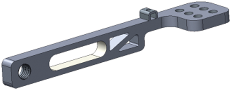
Figure 13: Brake pedal
The pivot pin is the component about which the brake pedal pivots. The movement of this pin helps in achieving the different brake pedal ratios. The pin is made up of mild steel for its availability. A hole is drilled at the center and internal threads are provided such that the stepper motor output shaft can transmit the axial load for the sliding movement of the pivot pin within the slot provided in the brake pedal (Fig. 14).

Figure 14: Pivot pin
5.5 Construction and Operating Method Leverage
The load adaptive braking system is an adaptive system that varies the braking force at the wheels based on the input from the load (kg). A microcontroller is used to which the various electronic components such as a stepper motor, an Adriano Uno, 4 * 4 keypad, 16 * 2 digital display, and a driver controller circuit are connected. Based on the input (i.e.,) the load (kg), the microcontroller determines the leverage ratio and moves the pivot pin within the slot, so that a precise brake force is exerted at the tire-road interface thereby enabling an optimum braking and minimum stopping distance preventing the wheel lock-up of inefficient braking (Fig. 15). When the mechanical brake pedal depresses by the driver, a braking force to the pedal position is transmitted to the tire. Based on the inputs from the load, the microcontroller calculates the pedal position, and the optimum braking pressure is developed in the master cylinder. When the load value is entered in Adriano Uno, a microcontroller instructs the stepper motor drive control to rotate. When the square threaded output shaft rotates, the collar screwed to the shaft slides away from the motor or towards the motor based on the direction of rotation of the output shaft. Hence, the collar slides away from the motor, it exerts a force corresponding to the motor torque and thus the pivot position is changed. The output shaft of the master cylinder is attached to the end of the pedal as shown in figures. Thus, this lever force presses the piston inside the master cylinder causing the build-up of pressure within the cylinder. This rise in pressure is exerted as the force on the rotor through the caliper pads.
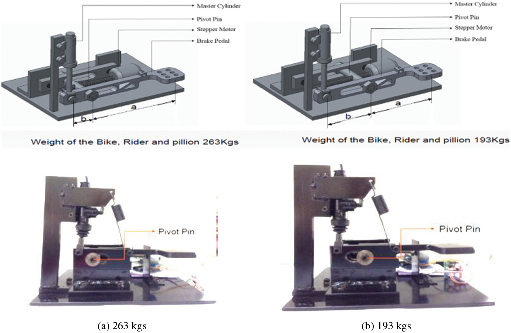
Figure 15: Weight of the bike, rider, and pillion
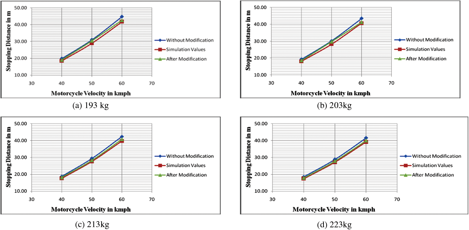
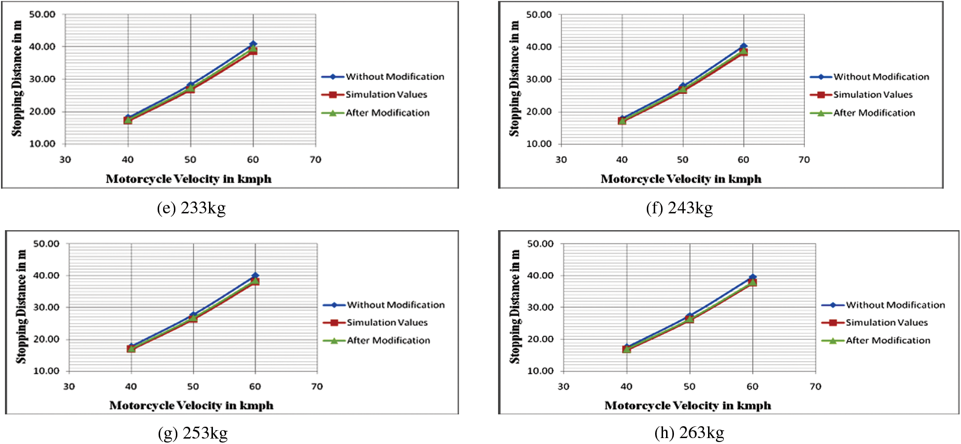
Figure 16: Velocity vs. stopping distance
In Table 10 the results show that when the vehicle load varies from 193 to 263 kg with different vehicle speeds the proportional amount of stopping distance of the vehicle is reduced significantly when the adaptive braking system was used instead of the conventional braking system.

From Fig. 16, it is perceived that the stopping distances changes with the vehicle speed. When the speed of the vehicle was 40, 50, and 60 kmph and the proportionate amount of stopping distances are changed, then the results are compared to the conventional braking system with the proposed braking system (theoretically and experimentally). The result shows that the modification braking system gives the optimum result in all the conditions (different loads on the vehicle and the various vehicle velocities). In general, the mechanical leverage ratio and Deceleration are depended on the vehicle load and are independent of the vehicle speed. When the vehicle has a minimum load, i.e., a motorcycle weight of 143 kg and a driver weight of 50 kg (193 kg), then the optimum mechanical leverage ratio become 2.93 and the respective deceleration of the vehicle is −3.23 m/s2. In addition to driver weight, a pillion load of 70 kg is added to the motorcycle, then the optimum mechanical leverage ratio become 4.404 and the deceleration of the vehicle attains −3.64 m/s2.
In this work, a modified variable braking system is proposed in the rear axle of the motorcycle to improve the performance of the conventional braking system under different load conditions. A small modification was done to the existing braking system where the brake pedal was available on the motorcycle. To optimize the conventional braking system, it was used to design and operate electromechanically. Therefore, a microcontroller was used to send the signal to the stepper motor to change the position of the brake leverage ratio based on the load cell input to the controller. The load cell was placed under the motorcycle seat; it was used to measure the various pillion loads on the motorcycle and accordingly, it will give input to the microcontroller. From the performance of the proposed scheme, it is concluded that the motorcycle stopping distance of the vehicle was reduced significantly than of the conventional braking system when the positioning of the brake pedal pivot point changed based on the pillion load on the motorcycle. In the future, this proposed scheme can be applied for four wheeler vehicles with revised vehicle parameters.
Funding Statement: The authors received no specific funding for this study.
Conflicts of Interest: The authors declare that they have no conflicts of interest to report regarding the present study.
References
1. S. H. Huo, L. Y. Yu, L. Y. Ma and L. Zhang, “Ride comfort improvement in post-brake phase using active suspension,” in Proc. of the ASME Design Engineering Technical Conf., vol. 1, pp. 1–6, Boston, MA, USA, 2015. [Google Scholar]
2. V. S. V. Satyanarayana, B. Sateesh and N. M. Rao, “Parameters optimisation of vehicle suspension system for better ride comfort,” International Journal of Vehicle Performance, vol. 4, no. 2, pp. 186–199, 2018. [Google Scholar]
3. J. Lee and S. Choi, “Braking control for improving ride comfort,” MATEC Web of Conferences, vol. 166, pp. 02002, 2018. [Google Scholar]
4. R. Du, G. Qiu, K. Gao, L. Hu and L. Liu, “Abnormal road surface recognition based on smartphone acceleration sensor,” Sensors, vol. 20, no. 2, pp. 451, 2020. [Google Scholar]
5. G. Prabhakar, S. Selvaperumal and P. N. Pugazhenthi, “Fuzzy PD plus I control-based adaptive cruise control system in simulation and real-time environment,” IETE Journal of Research, vol. 65, no. 1, pp. 69–79, 2019. [Google Scholar]
6. B. Goñi-Ros, W. J. Schakel and A. E. Papacharalampous, “Using advanced adaptive cruise control systems to reduce congestion at sags: An evaluation based on microscopic traffic simulation,” Transportation Research Part C: Emerging Technologies, vol. 102, pp. 411–426, 2019. [Google Scholar]
7. L. Hu, Y. Zhong and W. Hao, “Optimal route algorithm considering traffic light and energy consumption,” IEEE Access, vol. 6, pp. 59695–59704, 2018. [Google Scholar]
8. Z. Zhang, L. Zhang, L. Hu and C. Huang, “Active cell balancing of lithium-ion battery pack based on average state of charge,” International Journal of Energy Research, vol. 44, no. 4, pp. 2535–2548, 2020. [Google Scholar]
9. R. Rajamani, Adaptive Cruise Control. Vehicle Dynamics and Control, Boston, MA, USA: Springer US, vol. 1, pp. 141–170, 2012. [Google Scholar]
10. Y. -T. Lin, C. Y. Tseng, J. H. Kuang and Y. M. Hwang, “A design method for a variable combined brake system for motorcycles applying the adaptive control method,” Machines, vol. 9, pp. 31, 2021. https://doi.org/10.3390/machines9020031. [Google Scholar]
11. M. Heydrich, V. Ricciardi, V. Ivanov, M. Mazzoni, A. Rossi et al., “Integrated braking control for electric vehicles with in-wheel propulsion and fully decoupled brake-by-wire system,” Vehicles, vol. 3, pp. 145–161, 2021. [Google Scholar]
12. X. Wang, X. Wu, S. Cheng, J. Shi, X. Ping et al., “Design and experiment of control architecture and adaptive dual-loop controller for brake-by-wire system with an electric booster,” IEEE Transactions on Transportation Electrification, vol. 6, no. 3, pp. 1236–1252, 2020. [Google Scholar]
13. S. Chen, X. Zhang and J. Wang, “Sliding mode control of vehicle equipped with brake-by-wire system considering braking comfort,” Shock and Vibration, vol. 2020, pp. 5602917, 2020. https://doi.org/10.1155/2020/5602917. [Google Scholar]
14. W. Wu, D. Zou, J. Ou and L. Hu, “Adaptive cruise control strategy design with optimized active braking control algorithm,” Mathematical Problems in Engineering, vol. 2020, pp. 8382734, 2020. https://doi.org/10.1155/2020/8382734. [Google Scholar]
15. P. Mei, H. R. Karimi, S. Yang, B. Xu and C. Huang, “An adaptive fuzzy sliding-mode control for regenerative braking system of electric vehicles,” International Journal of Adaptive Control Signal Process, vol. 36, pp. 391–410, 2022. [Google Scholar]
16. D. Savitski, D. Schleinin, V. Ivanov and K. Augsburg, “Robust continuous wheel slip control with reference adaptation: Application to the brake system with decoupled architecture,” IEEE Transactions on Industrial Informatics, vol. 14, no. 9, pp. 4212–4223, 2018. [Google Scholar]
17. P. Ujwal and S. Krishna, “Fuzzy based adaptive control of antilock braking system,” International Journal of Engineering Research & Technology (IJERT), vol. 5, no. 5, pp. 139–143, 2016. [Google Scholar]
18. M. Tanelli, M. Corno, I. Boniolo and S. M. Savaresi, “Active braking control of two-wheeled vehicles on curves,” International Journal of Vehicle Autonomous Systems, vol. 7, no. 3, pp. 243–269, 2010. [Google Scholar]
19. M. S. Manikandan, K. V. Nithish Kumar, M. Krishnamoorthi and V. Ganesh, “Control of braking force under loaded and empty conditions on two wheeler,” World Academy of Science, Engineering and Technology, International Journal of Mechanical and Mechatronics Engineering, vol. 7, no. 9, pp. 1–7, 2013. [Google Scholar]
20. M. Hadji, H. H. Ahadi and V. Hematian, “A study of the minimum safe stopping distance between vehicles in terms braking systems, weather and pavement conditions,” Indian Journal of Science and Technology, vol. 5, no. 10, pp. 1–7, 2012. [Google Scholar]
21. V. Ganesh and J. Janci Rani, “Design and control of variable braking force system on a two wheeler,” International Journal of Vehicle Design, vol. 60, no. 3, pp. 327–349, 2012. [Google Scholar]
22. N. Nantais and B. P. Minaker, “Active four wheel brake proportioning for improved performance and safety,” SAE Technical Paper, vol. 1, pp. 1224, 2008. [Google Scholar]
23. M. Johnston, E. Leonard, P. Monsere and M. Riefe, “Vehicle brake performance assessment using subsystem testing and modeling,” SAE Technical Paper, vol. 1, pp. 0791, 2005. [Google Scholar]
24. S. Matsumoto, H. Yamaguchi, H. Inoue and Y. Yasuno, “Improvement of vehicle dynamics through braking force distribution control,” SAE Technical Paper, vol. 1, pp. 920645, 1992. [Google Scholar]
25. H. Peng and J. S. Hu, “Traction/braking force distribution for optimal longitudinal motion during curve following,” Vehicle System Dynamics, vol. 26, no. 4, pp. 301–320, 1996. [Google Scholar]
Cite This Article
 Copyright © 2023 The Author(s). Published by Tech Science Press.
This work is licensed under a Creative Commons Attribution 4.0 International License , which permits unrestricted use, distribution, and reproduction in any medium, provided the original work is properly cited.
 Downloads
 Citation Tools