
 Submit a Paper
 Propose a Special lssue
 Open Access
ARTICLE

NOMA with Adaptive Transmit Power Using Intelligent Reflecting Surfaces
1 Information Technology Department, Saudi Electronic University, Riaydh, Saudi Arabia
2 University of Carthage, SUPCOM-COSIM, Ariana, 2083, Tunisia
* Corresponding Author: Raed Alhamad. Email:
Computer Systems Science and Engineering 2023, 45(2), 2059-2070. https://doi.org/10.32604/csse.2023.032610
Received 23 May 2022; Accepted 24 June 2022; Issue published 03 November 2022
 View Full Text
 Download PDF
Abstract
In this article, we use Intelligent Reflecting Surfaces (IRS) to improve the throughput of Non Orthogonal Multiple Access (NOMA) with Adaptive Transmit Power (ATP). The results are valid for Cognitive Radio Networks (CRN) where secondary source adapts its power to generate low interference at primary receiver. In all previous studies, IRS were implemented with fixed transmit power and previous results are not valid when the power of the secondary source is adaptive. In CRN, secondary nodes are allowed to transmit over the same band as primary users since they adapt their power to minimize the generated interference. Each NOMA user has a subset of dedicated reflectors. At any NOMA user, all IRS reflections have the same phase. CRN-NOMA using IRS offers 7, 13, 20 dB gain vs. CRN-NOMA without IRS for N = 8, 16, 32 reflectors. We also evaluate the effects of primary interference. The results are valid for any number of NOMA users, Quadrature Amplitude Modulation (QAM) and Rayleigh channels.Keywords
Intelligent Reflecting Surfaces (IRS) are a good candidate for sixth generation 6G networks [1–3]. IRS phases are adjusted so that reflections have a zero-phase at all users [4–7]. IRS has been suggested for optical communications [8–10] and Millimeter Wave (mmWave) systems [11,12]. Experimental results of IRS have been presented in [13–15]. A practical implementation of IRS can be found in [16,17] were phase shifts can be continuous or quantized. Machine learning algorithms can be used to optimize the performance of IRS [18,19]. A real time cutting model using finite element was proposed in [20]. A fast and accurate tissue simulation model was discussed in [21]. Device to Device (D2D) communications for the fifth generation and beyond was studied in [22].
IRS can be used to reflect the transmitted signal to NOMA users. The source combines of symbols of K NOMA users. This signal is reflected by RIS toward K users. The weakest user detects its signal and considers the rest of signals as noise. The strongest user detects weakest user signal. Then, it removes it and continue the detection process of remaining users that are ranked from the weakest to the strongest one. IRS was implemented when the transmitter has a fixed transmit power in [1–19]. In all previous studies [1–19], IRS were implemented with fixed transmit power and previous results are not valid when the power of the secondary source is adaptive. In CRN, secondary nodes are allowed to transmit over the same band as primary users since they adapt their power to minimize the generated interference. In this paper, we derive the throughput of NOMA using IRS and adaptive transmit power.
In this article, we propose to:
– Compute the throughput of CRN using NOMA and IRS where the secondary source has an adaptive power. Each secondary NOMA user has a given set of reflectors.
– We derive the statistics of Signal to Noise Ratio (SNR) as well as Signal to Interference plus Noise Ratio (SINR). We study the effects of primary interference. CRN-NOMA using IRS offers 7, 13, 20 dB gain versus CRN-NOMA without IRS for N = 8, 16, 32 reflectors.
– Two algorithms are discussed to rank the NOMA users.
Next section gives the throughput when there are two users. Section 3 generalizes the results to CRN-NOMA with K users. Section 4 discusses the obtained results. The paper is concluded in last section.
Fig. 1 depicts the network model with two secondary users, a Source (SS), a Primary Receiver and Transmitter and PR and PT. SS adapts its power to have a small interference at PR. We consider Rayleigh channels. Let
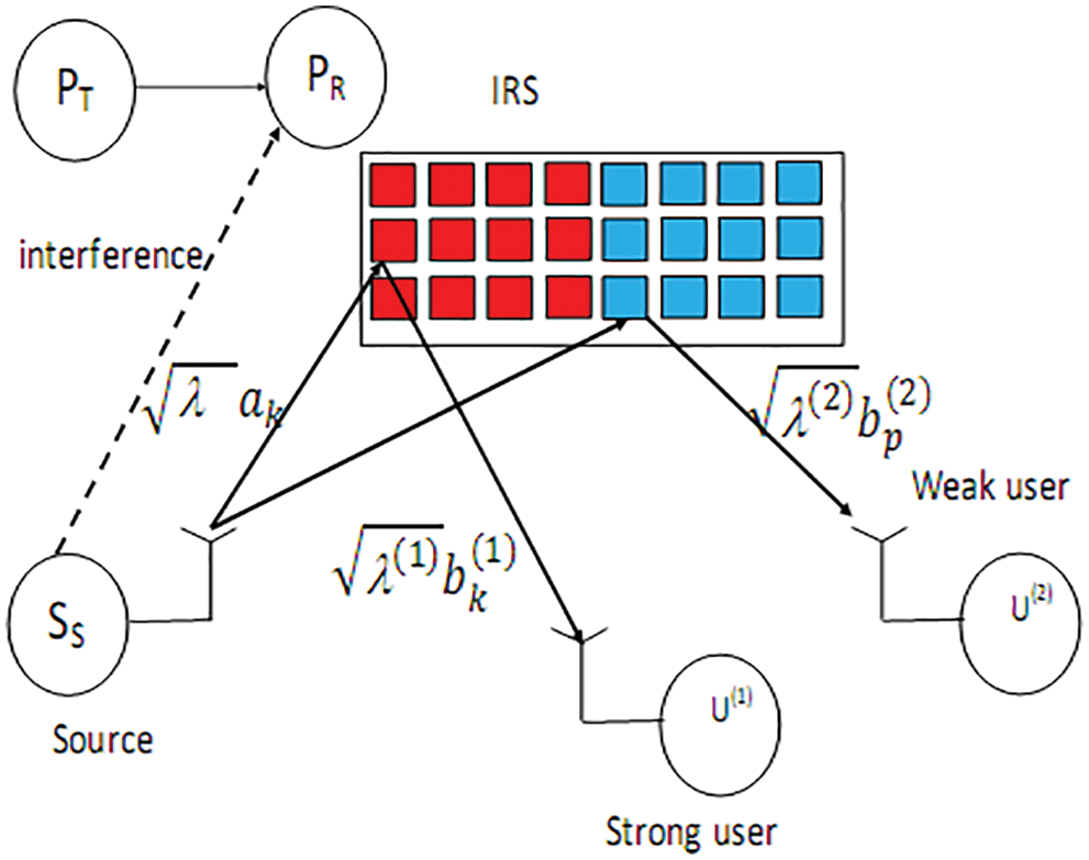
Figure 1: A network with two users
Let
The transmitted symbol by SS is written as
where s(i) is the symbol of U(i), poi is the power of U(i), po1 + po2 = 1 and 1 > po2 > po1 > 0.
The signal at U(i) given by
n(i) is an additive Gaussian r.v. with variance N0 and ESS is SS symbol energy defined as
Emax is the maximum symbol energy, I is the interference threshold and gSSPR is channel coefficient between SS and PR. SS verifies interference constraints as
Using (1), we obtain
where
Weak user U(2) estimates s(2) with SINR
where
The probability of an outage event at U(2) is given by
where the Cumulative Distribution Function (CDF) of
Then U(1) removes s(2) and demodulates s(1) with SNR
The probability of an outage event at U(1) is computed as
The Packet Error Probability (PEP) of U(i) is given by
where
L is packet length and
The throughput of U(i) is given by
The total throughput (TThr) is given by
We maximize the total throughput as follows
3.1 Ranking Using Average Gains
The network model is depicted in Fig. 2. It contains PT, PR, SS and K secondary NOMA users. U(i) has the i-th maximum average channel gain between SS and NOMA users. Let P be defined as
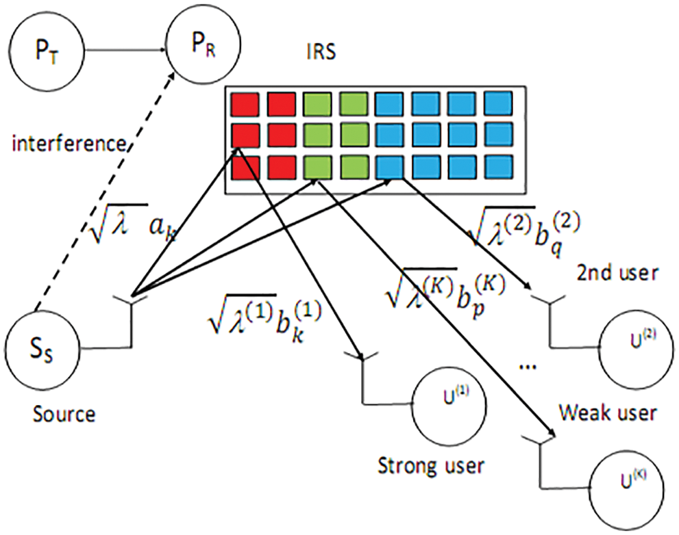
Figure 2: A network with K users
N(j) is the number of IRS reflectors of U(j).
NOMA symbol is written as
where po1 + po2 = 1 and 1>po2>po1 > 0.
The received signal at U(i) is written as
U(i) detects sK as poK > poi with SINR
Then U(i) performs Successive Interference Cancelation (SIC), removes sK to detect sK−1 with SINR
U(i) detects sp with SINR
The probability of an outage event at U(i) is computed as
The PEP at U(i) is equal to
where W0 is defined in (15)
The throughput of U(i) is given by
The total throughput (TThr) is given by
We maximize the total throughput as follows
3.2 Ranking Using Instantaneous Gains
Let Ui(1) be the strongest user with largest instantaneous channel gain B(i):
Let Ui(K) be the weakest user :
Let Ui(q) be q-th ranked user:
The CDF of
where 1 ≤ mi ≤ N for i = 1,…,N. m1¹m_2 ¹… mN, mq < mq + 1<…< mK and PB^(i)(x) is given in Appendix A.
The PEP and throughput can be computed as Section 3.1 where we have to replace PB(q)(x) by PBi(q)(x) given in (35).
4 Effects of Primary Interference
The SINR is computed as
The probability of an outage at U(i) is computed as
where
Fig. 3 shows the total throughput for CRN-NOMA for K = 2, for I = 1 16 Quadrature Amplitude Modulation (QAM), dIRSU(i) = 1,1.5 i = 1,2 Packet length is L = 200.. IRS allows 6, 12, 18 dB vs. CRN-NOMA without IRS for N = 8, 16, 32.
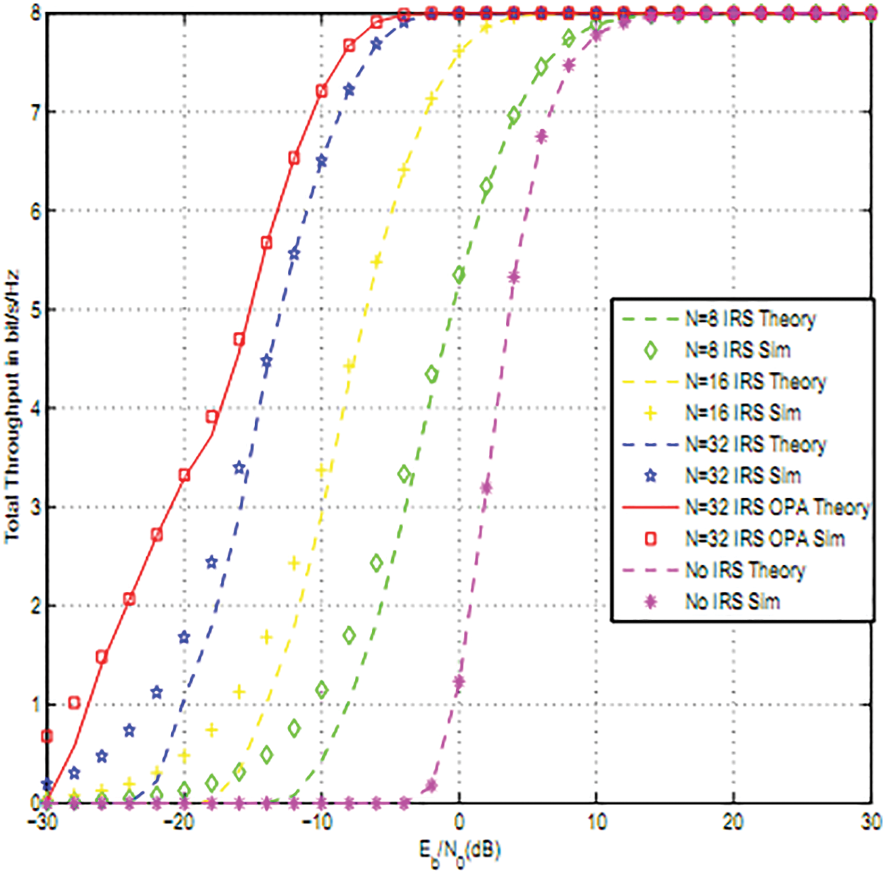
Figure 3: Total throughput for 2 users for 16QAM
Fig. 4 shows the throughput for different values of I, 16QAM modulation and N = 8 reflectors. As I increases as the throughput improves since SS can increase its power while verifying interference constraints.
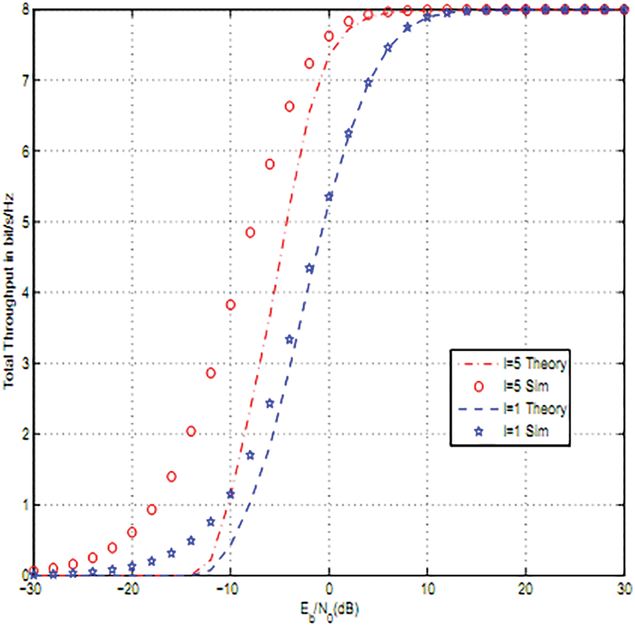
Figure 4: Effect of interference threshold I: 2 users, 16QAM and N = 8 reflectors
Fig. 5 shows that NOMA with IRS for N = 64 offers better performance than Orthogonal Multiple Access (OMA) and NOMA without IRS for 16QAM and two users. At high average SNR, the throughput of OMA is half that of NOMA.
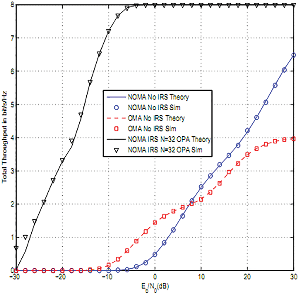
Figure 5: OMA and NOMA performance comparison
Fig. 6 depicts the effects of primary interference when there are two users, N = 8, 16 reflectors per user for 16QAM Modulation. The parameters are dPTU(i) = 1,0.9, 0.5,0.6. We notice that the performance degrades as PT is close to NOMA users since there is more interference.

Figure 6: Effects of primary interference on Total throughput of NOMA: 2 users, 16QAM modulation and N = 16
Fig. 7 depicts the total throughput for 16-QAM modulations for two users and N = 8, 16 reflectors. Ranking using instantaneous channel gains offers the best throughput.
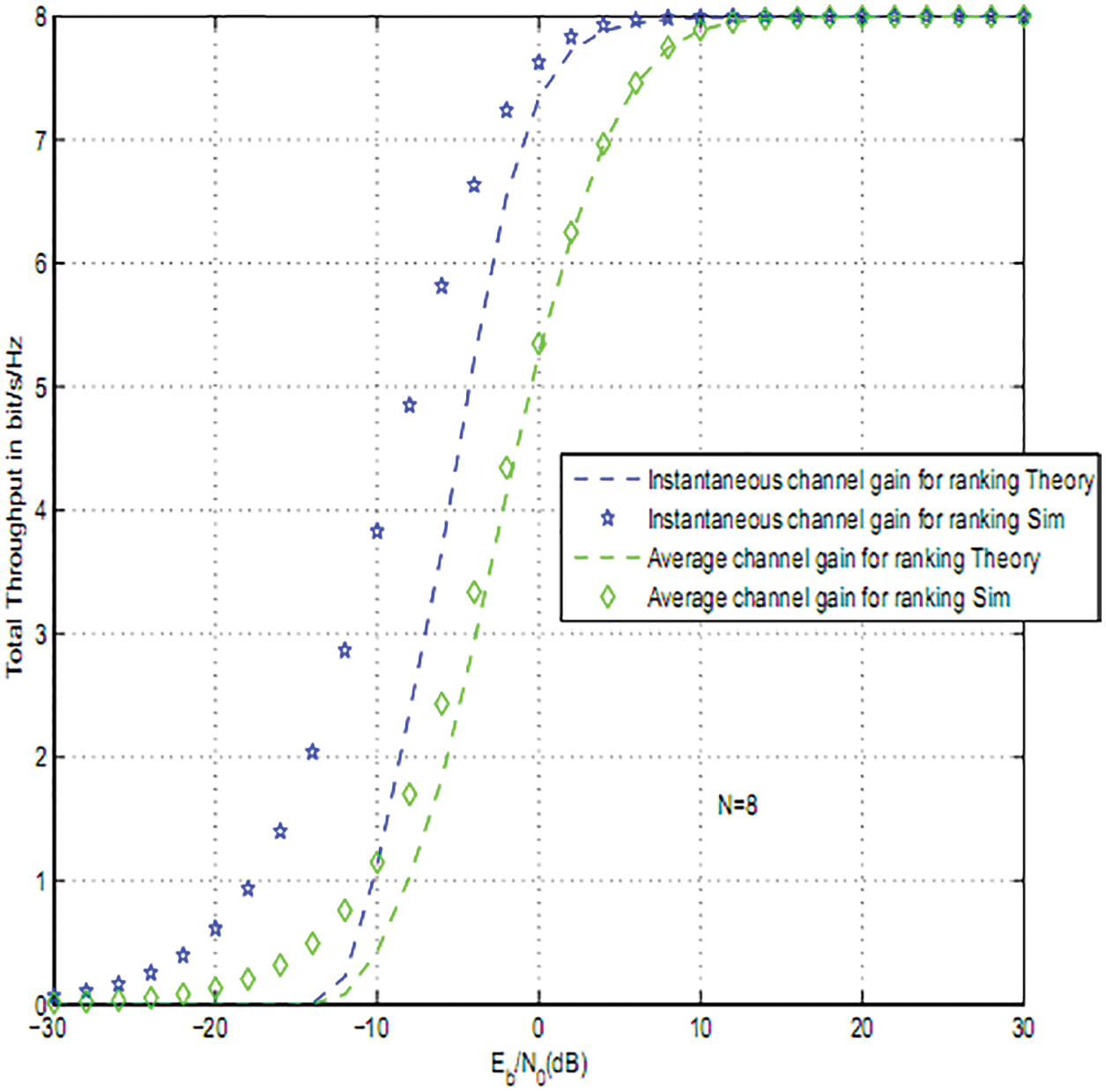
Figure 7: Secondary throughput for 16QAM modulation and different ranking strategies: N = 8
In this article, we computed the PEP and throughput of NOMA with adaptive transmit power and IRS. IRS are deployed to enhance data reception at all users. CRN-NOMA using IRS offers 7, 13, 20 dB gain vs. the absence of IRS for N = 8, 16, 32. We have also derived the SNR and SINR statistics.
Funding Statement: The authors extend their appreciation to the Deanship of Scientific Research at Saudi Electronic University for funding this research work through the Project Number 8093.
Conflicts of Interest: The authors declare that they have no conflicts of interest to report regarding the present study.
References
1. K. Ying, Z. Gao, S. Lyu, Y. Wu, H. Wang et al., “GMD-Based hybrid beamforming for large reconfigurable intelligent surface assisted millimeter-wave massive MIMO,” IEEE Access, vol. 8, no. 2, pp. 19530–19539, 2020. [Google Scholar]
2. L. Yang, W. Guo and I. Ansari, “Mixed dual-hop FSO-RF communication systems through reconfigurable intelligent surface,” IEEE Communications Letters, vol. 24, no. 7, pp. 1558–1562, 2020. [Google Scholar]
3. B. Di, H. Zhang, L. Li, L. Song, Y. Li et al., “Practical hybrid beamforming with finite-resolution phase shifters for reconfigurable intelligent surface based multi-user communications,” IEEE Transactions on Vehicular Technology, vol. 69, no. 4, pp. 4565–4570, 2020. [Google Scholar]
4. Q. Nadeem, A. Kammoun, A. Chaaban, M. Debbah and M. Alouini, “Asymptotic max-min SINR analysis of reconfigurable intelligent surface assisted MISO systems,” IEEE Transactions on Wireless Communications, vol. 19, no. 12, pp. 7748–7764, 2020. [Google Scholar]
5. W. Zhao, G. Wang, S. Atapattu, T. Tsiftsis and C. Tellambura, “Is backscatter link stronger than direct link in reconfigurable intelligent surface-assisted system?,” IEEE Communications Letters, vol. 24, no. 6, pp. 1342–1346, 2020. [Google Scholar]
6. S. Li, B. Duo, X. Yuan, Y. Liang and M. Renzo, “Reconfigurable intelligent surface assisted UAV communication: Joint trajectory design and passive beamforming,” IEEE Wireless Communications Letters, vol. 9, no. 5, pp. 716–720, 2020. [Google Scholar]
7. L. Dai, B. Wang, M. Wang, X. Yang, J. Tan et al., “Reconfigurable intelligent surface-based wireless communications: Antenna design, prototyping and experimental results,” IEEE Access, vol. 8, no. 3, pp. 45913–45923, 2020. [Google Scholar]
8. S. Hua and Y. Shi, “Reconfigurable intelligent surface for green edge inference in machine learning,” in 2019 IEEE Globecom Workshops (GC Wkshps), vol. 2, no. 3, pp. 10–15, 2019. [Google Scholar]
9. C. Huang, G. Alexandropoulos, C. Yuen and M. Debbah, “Indoor signal focusing with deep learning designed reconfigurable intelligent surfaces,” in IEEE 20th Int. Workshop on Signal Processing Advances in Wireless Communications (SPAWC), vol. 3, no. 4, pp. 11–14, 2019. [Google Scholar]
10. E. Basar, M. Renzo, J. Rosny, M. Debbah, M. S. Alouini et al., “Wireless communications through reconfigurable intelligent surfaces,” IEEE Access, vol. 7, no. 2, pp. 116753–116773, 2019. [Google Scholar]
11. H. Zhang, B. Di, L. Song and Z. Han, “Reconfigurable intelligent surfaces assisted communications with limited phase shifts: How many phase shifts are enough?,” IEEE Transactions on Vehicular Technology, vol. 69, no. 4, pp. 4498–4502, 2020. [Google Scholar]
12. M. Renzo, “6G wireless: Wireless networks empowered by reconfigurable intelligent surfaces,” in 25th Asia-Pacific Conf. on Communications (APCC), vol. 1, no. 1, pp. 12–13, 2019. [Google Scholar]
13. E. Basar, “Reconfigurable intelligent surface-based index modulation: A new beyond MIMO paradigm for 6G,” IEEE Transactions on Communications, vol. 68, no. 5, pp. 3187–3196, 2020. [Google Scholar]
14. Q. Wu and R. Zhang, “Towards smart and reconfigurable environment: Intelligent reflecting surface aided wireless network,” IEEE Communications Magazine, vol. 58, no. 1, pp. 106–112, 2020. [Google Scholar]
15. C. Huang, A. Zappone, G. Alexandropoulos, M. Debbah and C. Yuen, “Reconfigurable intelligent surfaces for energy efficiency in wireless communication,” IEEE Transactions on Wireless Communications, vol. 18, no. 8, pp. 4157–4170, 2019. [Google Scholar]
16. G. C. Alexandropoulos and E. Vlachos, “A hardware architecture for reconfigurable intelligent surfaces with minimal active elements for explicit channel estimation,” in ICASSP 2020–2020 IEEE Int. Conf. on Acoustics, Speech and Signal Processing (ICASSP), Spain, Barcelona, vol. 1, no. 1, pp. 9175–9179, May 4–8, 2020. [Google Scholar]
17. H. Guo, Y. Liang, J. Chen and E. Larsson, “Weighted sum-rate maximization for reconfigurable intelligent surface aided wireless networks,” IEEE Transactions on Wireless Communications, vol. 19, no. 5, pp. 3064–3076, 2020. [Google Scholar]
18. V. Thirumavalavan and T. Jayaraman, “BER analysis of reconfigurable intelligent surface assisted downlink power domain NOMA system,” in 2020 Int. Conf. on COMmunication Systems and NETworkS (COMSNETS), Bangalore, India, vol. 1, no. 2, pp. 519–522, January 7–11, 2020. [Google Scholar]
19. C. Pradhan, A. Li, L. Song, B. Vucetic and Y. Li, “Hybrid precoding design for reconfigurable intelligent surface aided mmwave communication systems,” IEEE Wireless Communications Letters, vol. 9, no. 7, pp. 1041–1045, 2020. [Google Scholar]
20. X. R. Zhang, W. Z. Zhang, W. Sun, H. L. Wu, A. G. Song et al., “A Real-time cutting model based on finit element and order reduction,” Computer System Science and Engineering, vol. 43, no. 1, pp. 1–15, 2022. [Google Scholar]
21. X. R. Zhang, H. L. Wu, A. G. Song and S. K. Jha, “A fast and accurate tissue simulation model based on point primitive method,” Intelligent Automation and Soft Computing, vol. 27, no. 3, pp. 873–889, 2021. [Google Scholar]
22. M. S. M. Gismalla, A. I. Azmi, M. R. Bin Salim, M. Faiz, F. Iqbal et al. “Survey on device to device (D2D) communication for 5GB/6G networks: Concept, applications, challenges, and future directions,” IEEE Access, vol. 10, no. 1, pp. 30792–30821, 2022. [Google Scholar]
Appendix A: CDF of B(i)
The variance and mean of A(i) are
We deduce
where
where λSSPR = E(|gSSPR|2), E(.) is the expectation operation and gSSPR is the channel coefficient between SS and PR. When I/|gSSPR|2>Emax, we have
and
where Qm(.,.) is the Generalized Marcum Q-function.
When I/|gSSPR|2<Emax ,
Cite This Article
 Copyright © 2023 The Author(s). Published by Tech Science Press.
This work is licensed under a Creative Commons Attribution 4.0 International License , which permits unrestricted use, distribution, and reproduction in any medium, provided the original work is properly cited.
 Downloads
 Citation Tools