
 Submit a Paper
 Propose a Special lssue
 Open Access
ARTICLE

Copy Move Forgery Detection Using Novel Quadsort Moth Flame Light Gradient Boosting Machine
1 Department of Computer Applications, Noorul Islam Centre for Higher Education, Nagercoil, 629180, India
2 Department of Computer Science Engineering, Noorul Islam Centre for Higher Education, Nagercoil, 629180, India
* Corresponding Author: R. Dhanya. Email:
Computer Systems Science and Engineering 2023, 45(2), 1577-1593. https://doi.org/10.32604/csse.2023.031319
Received 14 April 2022; Accepted 08 June 2022; Issue published 03 November 2022
 View Full Text
 Download PDF
Abstract
A severe problem in modern information systems is Digital media tampering along with fake information. Even though there is an enhancement in image development, image forgery, either by the photographer or via image manipulations, is also done in parallel. Numerous researches have been concentrated on how to identify such manipulated media or information manually along with automatically; thus conquering the complicated forgery methodologies with effortlessly obtainable technologically enhanced instruments. However, high complexity affects the developed methods. Presently, it is complicated to resolve the issue of the speed-accuracy trade-off. For tackling these challenges, this article put forward a quick and effective Copy-Move Forgery Detection (CMFD) system utilizing a novel Quad-sort Moth Flame (QMF) Light Gradient Boosting Machine (QMF-Light GBM). Utilizing Borel Transform (BT)-based Wiener Filter (BWF) and resizing, the input images are initially pre-processed by eliminating the noise in the proposed system. After that, by utilizing the Orientation Preserving Simple Linear Iterative Clustering (OPSLIC), the pre-processed images, partitioned into a number of grids, are segmented. Next, as of the segmented images, the significant features are extracted along with the feature’s distance is calculated and matched with the input images. Next, utilizing the Union Topological Measure of Pattern Diversity (UTMOPD) method, the false positive matches that took place throughout the matching process are eliminated. After that, utilizing the QMF-Light GBM visualization, the visualization of forged in conjunction with non-forged images is performed. The extensive experiments revealed that concerning detection accuracy, the proposed system could be extremely precise when contrasted to some top-notch approaches.Keywords
In recent days, as several images have been encountered in each day of life, digital media has evolved into a vital aspect of living. In a broad range of industries, images play a vital role in communicating valuable information [1]. It is extremely intricate to express complex information (scenes) in words, whereas the images are influential and effective to pass intricate information [2]. In these days, as there is a huge amount of image processing and editing software, images are easily handled and modified. The mechanism of moulding, modifying, or copying images and documents is proffered as Forgery [3]. For exemplar, a critical power accident occurs in the power maintenance sector owing to the forgery of related images. During the court trials, the criminals do not get the punishment they deserve for the crime in forgery of scene images, which creates a great impact on the social harmony and steadiness [4]. Copy-move, splicing, and retouching are several forms of image forgery. In the image splicing technique, to create the forged images, specific portions from diverse images are spliced. To execute image retouching, the geometric transformation techniques say flipping, rotation, skewing, stretching, and scaling are incorporated [5]. An image’s particular section is copied from one location, along with pasted, in a dissimilar location on to the same image in Copy-Move Forgery (CMF) [6,7]. An image’s one section is copied together with background and moved to the same image’s different areas in CMF [8]. Prior to pasting elsewhere, the duplicated portion may undergo some alterations, say scaling and modifications in brightness [9]. By the procedure of copy-move, an image may be counterfeited to hide or alter its sense [10,11]. It is complex to examine CMF with the naked eye if done carefully despite being one of the prevalent image modifications, along with it is intricate to prove the images’ legitimacy for the forensic analyst [12,13]. So owing to these problems, the security and trustworthiness of media information are damaged [14]. There is an acute requirement for creating methodologies that are competent in checking and certifying digital original images owing to the rising prevalence of image falsification [15]. To discover image misrepresentation, numerous developments have been researched and proposed. Keypoint-based and Block-based approaches are the classifications of the CMFD technique. A general processing frame followed by the ‘2’ CMFD classifications are; Feature Extraction (FE), Feature Matching (FM) and post-processing [16]. Images are then separated into several image blocks in block-based CMFD techniques, from which features are extracted. From an image, the key points are retrieved, and after that, the descriptors utilize these key points for FM in key-based CMFD techniques [17]. But, particularly in the FM stage, the time intricacy is large for prevailing methodologies, and the place of forged sections is not precise to meet practical needs. This work designed an efficient CMFD methodology utilizing the QMF-Light GBM, to subdue the prevailing difficulties.
The remaining work is structured as: The prevailing work associated with CMFD is represented in Section 2. The forgery detection method proposed is illustrated in Section 3. The outcomes along with discussions are analysed in Section 4. The conclusion is illustrated in the last section.
Meena et al. [18] suggested a CMFD scheme, utilizing the Tetrolet transform. Primarily, image inputted is separated into intersecting blocks. After that Tetrolet transform extracted ‘4’ low-pass coefficients along with ‘12’ high-pass coefficients from every extracted segments. Following that, the feature vectors were lexicographically arranged, and associated blocks were discovered by correlating with the retrieved Tetrolet features. Though the copied portions had undergone certain post-processing activities, the method discovered and located the counterfeited portions correctly, as revealed by the experiment’s outcomes. But, a large computational difficulty was the limitation here.
Meena et al. [19] presented a cross method by combining the block-based and keypoint-based method utilizing Fourier-Mellin Transform (FMT) and Scale Invariant Feature Transform (SIFT) respectively. Primarily, image under investigation was split into texture and smooth portions. The SIFT was then utilized to extract key points as of the image’s texture area. After that, for the image’s smooth portion, the FMT was adapted. Next, to discover the image’s copied portions, the extracted characters were matched. On comparing the prevailing CMFD methodologies, the investigation outcomes showed that this system performed better. For greatly distorted images, this system was ineffective. Wang et al. [20] created a rapid and effectual CMFD utilizing adaptive keypoint extraction along with processing, initiating the quick tough invariant feature, and screening out incorrect duals. Initially, using quick approximated LoG filter and uniformity processing, the constant distribution keypoints were retrieved flexibly as of the forged image. The rapid robust invariant attribute was then utilized for defining the image keypoints, which were then matched via the Rg2NN algorithm. Ultimately, by utilizing optimized mean-residual normalized production correlation, the duplicated portions were localized, and the incorrectly matched pairs were eliminated by implementing the segmentation-based candidate clustering. When analogized with the prevailing methodologies, the comprehensive research exhibited the method’s efficiency. Yet, in smooth images, the approach was unsuccessful in identifying forgery.
Hegazi et al. [21] designed an enhanced method for keypoint-based CMFD. Density-oriented clustering and the Guaranteed Outlier Removal algorithm were utilized to build the approach. The faked patch was recognized more precisely whilst lowering time along with space difficulty by exploiting density-based grouping algorithm. To minimize wrong matches more efficiently, the Guaranteed Outlier Removal (GORE) algorithm was used along with the RANdom SAmple Consensus (RANSAC) algorithm. Given multiple challenging situations, the methodology transcended the prevailing methods and this was revealed from the outcomes that were executed on several benchmark datasets. The RANSAC method was utilized to eradicate the wrong matches, but it only decreased the wrong matches and failed to produce accurately matched keypoint pairs. Zhu et al. [22] used Adaptive attention and Residual Refinement Network (AR-Net) to investigate end-to-end neural network. Particularly, the adaptive attention method was employed to amalgamate the position along with channel attention attributes, to completely get context details together with enhancing the feature’s representation. Next, to gauge the self-correlation among feature maps, along with Atrous Spatial Pyramid Pooling (ASPP), deep matching was employed and correlation maps scaled were merged to construct the abrasive mask. Lastly, residual refinement segment was used to optimize the abrasive mask that preserved object’s boundary structure. It was evident from the experimental findings that the AR-Net outperformed the prevailing algorithms. But, the technique took a long time for computation.
Qadir et al. [23] described a passive block-based technique for identifying CMF in images, which were distorted by post-processing threats like compression and sound. The approach functioned by separating the image into intersecting blocks, and then extracting features of these individual blocks utilizing Discrete Cosine Transform (DCT). Then, to build feature vectors regarding the DCT coefficient’s sign information, the Cellular Automat was utilized. Lastly, to discover the forged parts, matching of feature vectors was done utilizing the KD-tree-based nearest-neighbour searching technique. Though an image was extremely damaged by post-processing attacks, the outcomes illustrated that the suggested method performed extraordinarily well when analogized with the prevailing techniques. But, owing to computation of feature vectors and more images blocks being matched, the method took high cost for computation.
3 Proposed Copy-Move Forgery Detection System
Owing to advancement of image editing software, there has been a rapid increase in image manipulation; in addition, with this enhancement, the image falsification is performed devoid of degrading its quality or leaving any traces. The procedure of copying an image’s particular portion and fixing it in the same image’s some other portion is mentioned as CMF, which is an extensively utilized forgery model. The major intention of such tampering is to misinform people by hiding some valuable data or by replicating things. To identify CMF, a huge number of methodologies have been presented, which primarily focussed on two categories: (i) centred on the block feature and (ii) centred on the key-point feature. Initially, the forged image is separated into overlapping or non-overlapping blocks in the block-centric model. Afterwards, the FE along with FM is executed. Conversely, the keypoint-centred methodology is reliant on the identification of higher-entropy image parts. In an image, the candidate key points are the pixels’ local maxima along with minima being extracted. There are few cons to the prevailing forgery detection methodologies. Therefore, producing an effectual CMFD model to detect along with to locate the forgery in digital images is highly essential. Consequently, for effectual CMFD, the QMF Light GBM model is proposed here. In the proposed framework, for the FM process, the block along with key-point features are extracted to make out the images being forged; then, to take away the false positive matches, which advanced in the FM, the outliers are detected utilizing the UTMOPD; finally, to visualize if the image is forged or not, the visualization is done utilizing the QMF-Light GBM. Fig. 1 demonstrates the proposed model’s block diagram.
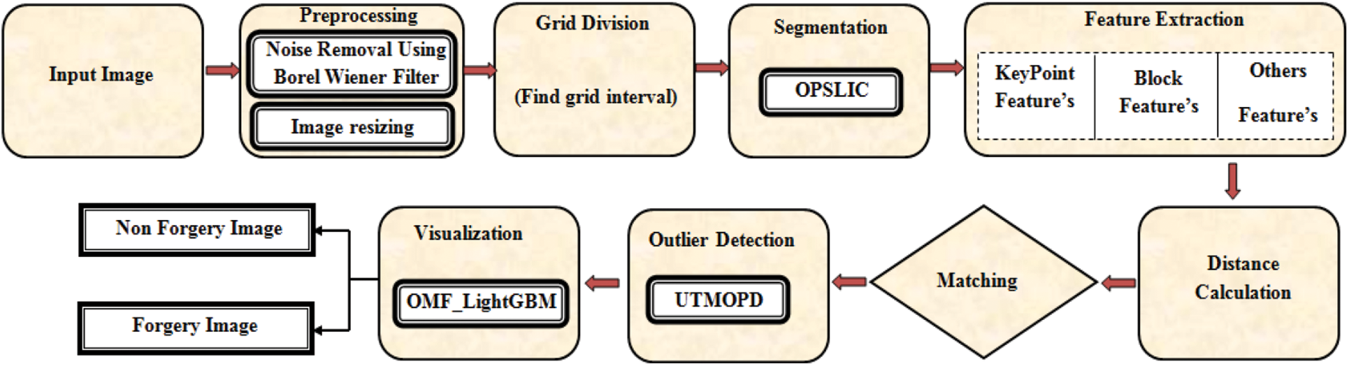
Figure 1: Proposed QMF_light GBM methodology block diagram
Enhancing image’s quality by suppressing unnecessary distortions ameliorating certain features is the intention of pre-processing; thus, the image can be evaluated effectively. The pre-processing includes conversion, image resizing, filtering, together with brightness transformation. Noise removal and image resizing are the two steps utilized for pre-processing the input images, which are initialized as,
where, the number of input images is specified as
Then, in the noise removal process, the noise is removed utilizing the BWF. The received signal together with the estimated noise-removal signals is analogized to alleviate the noise by the Wiener Filter. The frequency components degraded by the noise aren’t reconstructed, and also the filters are not capable of restoring components in the conventional Wiener Filter. The Fourier transform is replaced by the BT in the BWF to trounce the aforementioned issues. The noise removed image
where, the received signal is specified as
where, the BT is specified as
where, the complex function attained utilizing the complex variable
where, the resized image is notated as
The
Firstly, the input image is transformed to the CIELAB Color Space (CS) in which by utilizing all pixels of image along with the magnitude of super-pixels, the image’s grid interval is calculated. A uniform CS is provided by CIELAB by illustrating all perceivable colors mathematically in ‘3’ dimensions namely
where, the grid interval is denoted as
where, the pixel coordinates in the image are specified as X, Y, the cluster centre is indicated as
After that, the distance betwixt every single pixel in the search region
where, distance betwixt coordinates of every single pixel and the cluster centre is exhibited as
Every single pixel
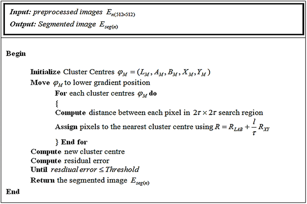
Figure 2: Pseudo-code of the OPSLIC algorithm
The basic steps in the OPSLIC are elaborated in Fig. 2. In this, by grouping pixels, which share the same characteristics into regions, the segmented images are generated together with it is specified as
Following segmentation, the FE is executed wherein the segmented images
■ Key Point Features: Information about the image content is termed as a key point feature. It provides data about the image’s structures like edges, points, or objects. These features are calculated by pondering a region of certain pixel intensities in the region of it. Corner, edge, Difference of Gaussian (DoG), Laplacian of Gaussian (Log), dense-field features, Determinant of Hessian (DoH), Oriented Fast and Rotated Brief (ORB), sparse-field features, Binary Robust Independent Elementary Features (BRIEF) are keypoint features being extracted. Consequently, the feature is specified as,
■ Block Features: The block features comprise the linear amalgamation of actual features. Discrete Wavelet Transform (DWT), DCT, Singular Value Decomposition (SVD), and Principal Component Analysis (PCA) are the block features being extracted. The block features being extracted are indicated as,
■ Other Features: Illumination features, multiscale features, content-centric image features, and geometric features like scaling along with rotation, SIFT are the other features being extracted. These features are signified as,
Lastly, the features being extracted are formulated as,
where, the total number of features including keypoint features
By utilizing the distance measure, the similarity betwixt every single feature descriptor is measured following the completion of FE. After that, to identify the forged region, the copy-move along with actual input images’ distance value is matched. After FM, there may occur some false positive matches that specify an image as a forgery image even when the image is a non-forgery image. Consequently, by utilizing the UTMOPD, the outlier detection is conducted further to avoid such false matches termed outliers.
By utilizing the UTMOPD, the outlier detection is performed for the image
The adjacency matrix of the set of samples’ mutual k-nearest neighbour is plotted in the graph, which is signified as,
where, the set of
where, set of labelled points
where, the union of
3.4.2 Computation of Graph Communities
A group of nodes, which have additional links connecting nodes of the same group, is mentioned as communities. Here, regarding the maximal union of adjacent
As of the degree function, the internal connectivity of
Next, the connectivity betwixt the isolated node and
Consequently, the isolated node is appended to the primarily identified community when it meets the criterion,
where, the term
3.4.3 Classification of Inliers and Outliers
In this, the inliers along with the outliers are distinguished and mapped to the square function’s various corners. It is proffered utilizing the local measure of irregularity as of ‘2’ probabilistic measures gauged in its set of neighborhoods. Class outliers and attribute outliers are the ‘2’ types of outliers. Attribute outliers are specified as the nodes not belonging to any of the identified communities. Class outliers are the nodes that are expected to belong to communities with a higher heterogeneity in nodes label or belong to the majority of nodes with a label varied as of the class outlier label. The heterogeneity of the community that sample belongs to is gauged as,
where, heterogeneity of community labels utilizing the probability of
The images
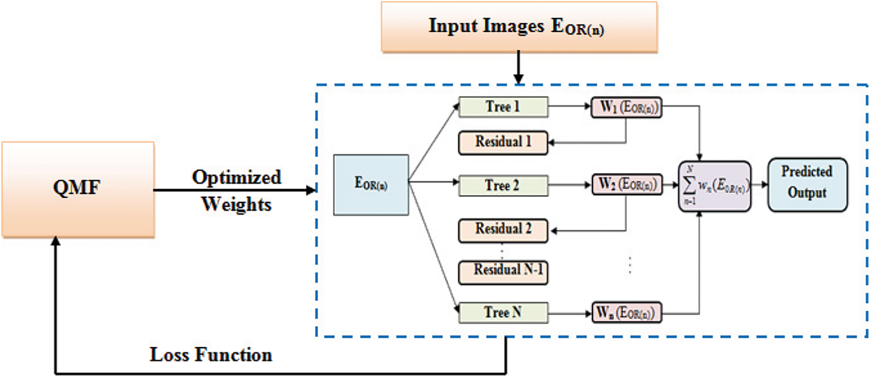
Figure 3: Architecture of QMF-Light GBM
Numerous regression trees are incorporated to make a Light GBM as,
where, the prediction after a regression tree
where, the loss function gauged as the difference betwixt the prediction
where, the parameter that penalizes the number of leaves
where, the residual employed to fit the decision tree
Moth Flame Optimization (MFO) is a population-centred meta-heuristic algorithm motivated by the moths’ navigation behaviour in light. In MFO, by exchanging the position vectors, moths can fly in a hyper dimension space. Creating the initial population, updating the moth positions, and updating the number of flames are the ‘3’ major steps included in the MFO. Quick-sort is utilized by the prevailing MFO. The Quick-sort is extremely slow; thus, it is replaced by Quad-sort. Quad-sort is faster than Quick-sort for random data and for ordered data, it slightly faster than Tim-sort. Consequently, the algorithm is called as QMF.
3.5.1 Population Initialization
The moths’ populace (i.e., the weight of leaves to be optimized) is initialized as,
where, the number of moths is indicated as l, the number of parameters is specified as t. After that, regarding the fitness value, all moths are sorted as,
where, the fitness function is denoted as
Moreover, regarding the fitness value, the flames are sorted as,
where, the flames are indicated as ℘. In this, the moths are the search agents, which move around the Search Space (SS), and the flames are the moths’ best position achieved until now in the SS.
3.5.2 Moth’s Position Updation
‘3’ significant functions are deployed here and are given as,
where, the moths’ random population along with fitness value is specified as
The significant function that moves the moths around the SS is specified as
where, the spiral function is symbolized as
where, the distance betwixt the
After that, by utilizing the fitness matrices, moths update their positions. This prevents from getting into the trap of local optima.
3.5.3 Number of Flames Updation
The number of flames is reduced as shown in Eq. (40) to ameliorate the QMF’s exploitation.
where, the maximum number of flames is denoted as L, the current iteration is specified as q, the maximum number of iterations is signified as
where, the optimal weight values utilized to train the Light GBM is symbolized as
where, the 1st and 2nd order gradient statistical outcomes of
where, the point at which the node is split is denoted as y, the number of samples on a fixed node is indicated as o. This process is repeated until the residual remains constant. Lastly, the predicted output verifies whether the input image is forged or not.
To check the efficiency of the proposed model, several experimentations are executed here. With 4 GB RAM and 3.20 GHz Intel i5/core i7 CPU, the entire experiment has been conducted. The PYTHON is employed as the working platform to execute the proposed CMFD utilizing QMF-Light GBM.
By utilizing two image datasets, MICC-F220 and MICC-F600, the proposed methodology’s performance is assessed. MICC-F220 dataset contains 220 images, of which 110 are tampered and 110 of which are originals, with sizes from 722 × 480 to 800 × 600 pixels. The MICC-F600 dataset contains 440 original images, 160 tampered images, and 160 ground truth images with sizes ranging from 800 × 532 to 3888 × 2592 pixels. For training and testing, data of 80% and 20% are utilized in the proposed model. In Figs. 4 and 5, the dataset’s sample images along with the outcome images of further processing are depicted.
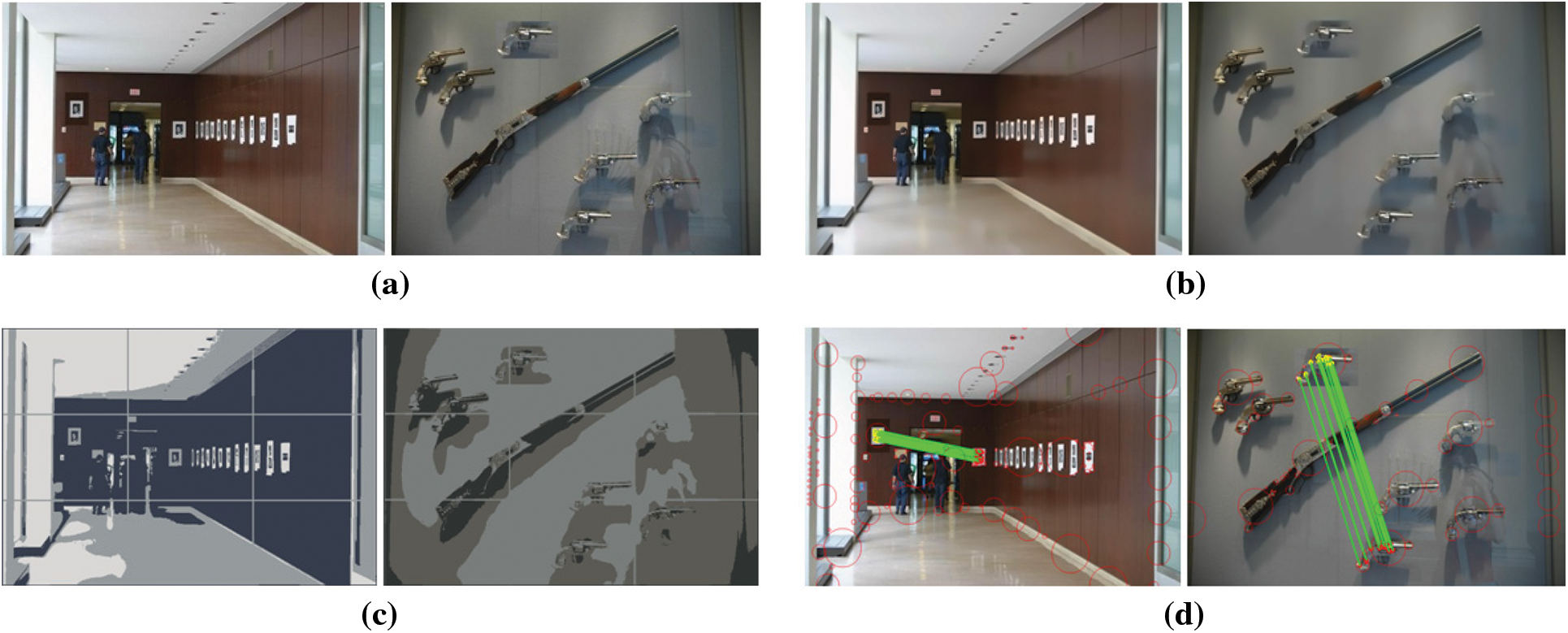
Figure 4: Sample images of single copy-paste (a) input images (b) pre-processed images (c) segmented images (e) images with matching points and detected copy paste part
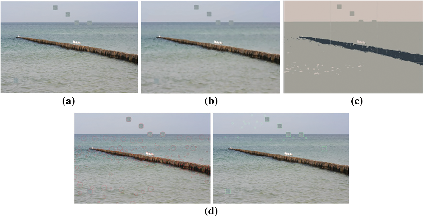
Figure 5: Sample images of multiple copy-paste (a) input image (b) pre-processed image (c) segmented image (d) images with matching points and detected copy paste part
The sample images’ single copy-paste detection is addressed in Fig. 4. Dataset’s input images are depicted in Fig. 4a, the pre-processed images are exhibited in Fig. 4b, the segmented images are demonstrated in Fig. 4c, and in Fig. 4d matching points together with detected copy paste section is presented. Multiple copy-paste detection in the sample image is interpreted in Fig. 5. The input image is elucidated in Fig. 5a, the pre-processed image is portrayed in 5(b), the segmented image is illustrated in 5(c), and in Fig. 5d the matching points along with copy-paste portions are depicted.
By analogizing with the prevailing Recurrent Neural Network (RNN), Artificial Neural Network (ANN), Convolution Neural Network (CNN), along with Deep Neural Network (DNN), the QMF-Light GBM is evaluated here. To examine the proposed methodologies’ performance, the parameters like specificity, sensitivity, accuracy, Negative Predictive Value (NPV), F-measure, False Positive Rate (FPR), Mathews Correlation Coefficient (MCC), False Negative Rate (FNR), as well as False Recognition Rate (FRR) are utilized.
Discussion: Regarding certain quality metrics, the proposed and prevailing technique’s performance is demonstrated in Tab. 1. The fraction of accurate image detection at which an image suffering from forgery is predicted correctly as the image is forged is measured by sensitivity, accuracy, and specificity. These values must be high, to attain enhanced performance. By having greater specificity, sensitivity, and accuracy values, the proposed model acquires enhanced performance and it is demonstrated in Tab. 1. Sensitivity of 98.3857, specificity of 93.9134, and accuracy of 97.2222 are achieved by the proposed model. The prevailing approaches, however, have lesser sensitivity, accuracy, and specificity than the proposed methodology. As a result of the investigation, the proposed model is incredibly accurate in finding forged areas. Fig. 6 reflects the pictorial representation of the aforesaid analysis.
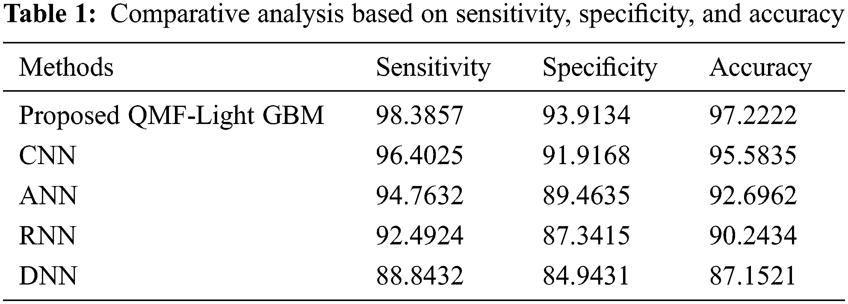
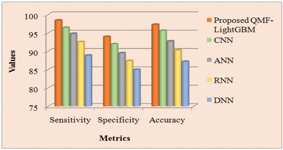
Figure 6: Performance analysis of proposed and existing methods
Discussion: The proposed along with the prevailing technique’s performance is shown in Tab. 2. To determine analysis accuracy F-measure is utilized, which is a weighted average of precision and recall. The number of true negatives is stated by the NPV, which is the likelihood that the image is actually non-forged after a negative outcome. For two classes, the MCC assesses the visualization’s quality. The greater the metrics’ values, the more precise the technique is. Tab. 2 displays that the proposed system achieves larger MCC, F-measure, and NPV than the prevailing techniques. The proposed technique has an F-measure of 94.36557, but the prevailing CNN, ANN, RNN, and DNN approaches have F-measures of 92.74325, 89.84532, 88.29857, and 86.48322 respectively. The proposed framework has F-measure superior to the prevailing techniques. Regarding NPV and MCC, the proposed system outperforms the prevailing techniques by a greater value of 94.36557 and 92.9973 respectively. Therefore, when analogized to the prevailing techniques, the proposed model performs superior. Fig. 7 depicts the findings of the examination of Tab. 1 graphically.
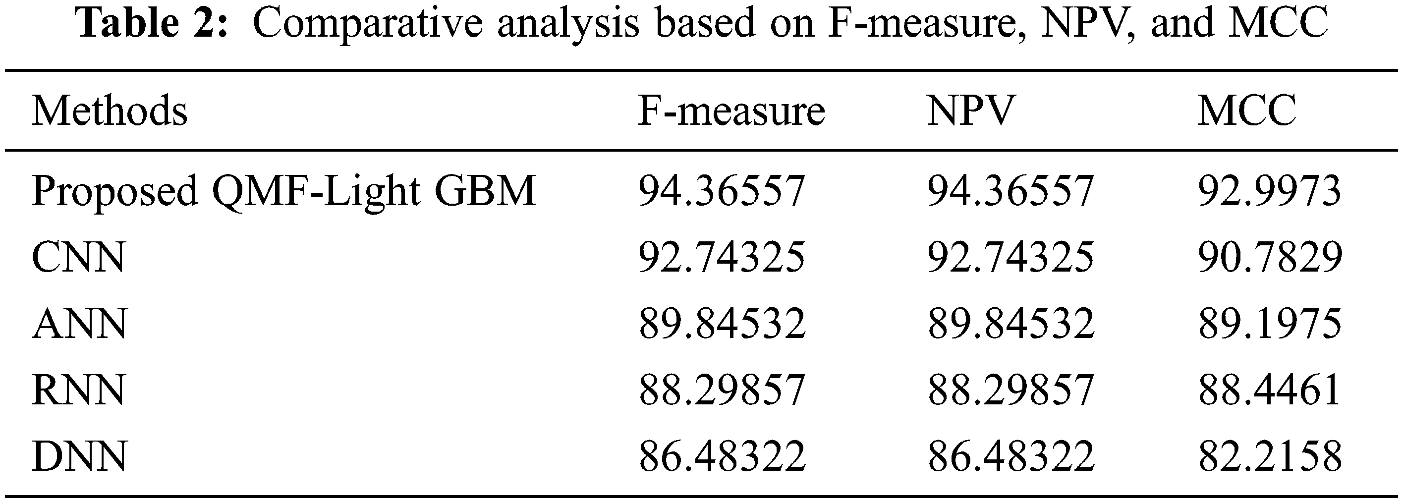
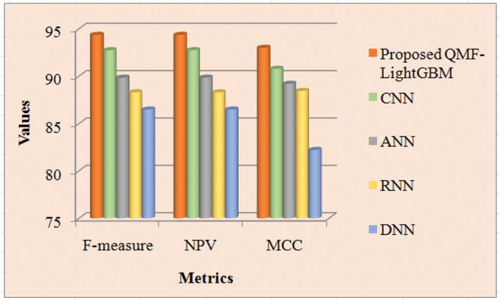
Figure 7: Performance comparison of proposed and existing methods
Discussion: The proposed and prevailing methodologies’ FPR, FNR, and FRR are inspected in Tab. 3. FNR is the false-negative cases’ appraisal, while FPR is the fraction of forged images wrongly observed as non-forged images. The metric that indicates how likely the system wrongly discards the forged images is termed FRR. It is claimed that the technique is highly accurate if it acquires lower values for these criteria. Thus, with the lesser values of FPR, FNR, and FRR, the proposed strategy produces superior outcomes, which is apparent from Tab. 1. The proposed methodologies’ FNR and FRR are equal to and lesser than the prevailing techniques that are 0.02124, and it is revealed from Tab. 3. The proposed model offers a value of 0.01197 for FPR. However, the prevailing methodologies’ FNR is 0.21101, 0.29859, 0.34262, and 0.51479 for CNN, ANN, RNN, and DNN respectively. The investigation reveals that the proposed approach has significantly lower FNR, FPR, and FRR values. Therefore, the acquired results revealed that the proposed system outperforms the prevailing CNN, ANN, RNN, and DNN approaches. Fig. 8 depicts a visual representation of the aforesaid analysis.
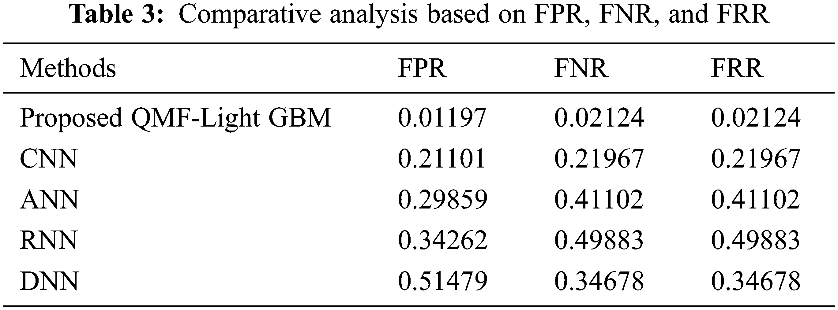
Figure 8: Performance analysis of proposed and existing methods
Since several transformations might be undergone by the forged region for making the forgery detection untraceable for human eyes, the CMF is highly complicated to identify. Therefore, a quick and precise CMFD is proposed for digital images. Detecting the forged parts efficiently utilizing a QMF-Light GBM is the paper’s key intention. ‘6’ stages namely, pre-processing, segmentation, FE, FM, outlier detection, and visualization are encompassed by the methodology. Concerning the performance metrics, the proposed QMF-Light GBM’s performance is examined with the existent CNN, ANN, RNN, and DNN methodologies in the experiential assessment. The images gathered from MICC-F220 and MICC-F600 datasets are utilized by the proposed methodology for performance analysis. Experimental results revealed that copy-move forged regions could be very efficiently and accurately identified by the proposed model with an accuracy of 97.2222, which is higher contrasted to the prevailing methods. The method suffers still from high computation time for the higher number of key points detected in the process. For detecting CMF in videos, the proposed work could be extended in the upcoming future.
Acknowledgement: The authors with a deep sense of gratitude would thank the supervisor for his guidance and constant support rendered during this research.
Funding Statement: The authors received no specific funding for this study.
Conflicts of Interest: The authors declare that they have no conflicts of interest to report regarding the present study.
References
1. G. Singh and K. Singh, “An improved block-based copy-move forgery detection technique,” Multimedia Tools and Applications, vol. 79, no. 1, pp. 13011–13035, 2020. [Google Scholar]
2. A. Dixit and S. Bag, “Utilization of edge operators for localization of copy-move image forgery using WLD-HOG features with connected component labeling,” Multimedia Tools and Applications, vol. 79, no. 3, pp. 26061–26097, 2020. [Google Scholar]
3. R. Agarwal and O. P. Verma, “An efficient copy move forgery detection using deep learning feature extraction and matching algorithm,” Multimedia Tools and Applications, vol. 79, no. 11, pp. 7355–7376, 2020. [Google Scholar]
4. X. Tian, G. Zhou and M. Xu, “Image copy-move forgery detection algorithm based on ORB and novel similarity metric,” IET Image Processing, vol. 14, no. 10, pp. 2092–2100, 2020. [Google Scholar]
5. S. Tinnathi and G. Sudhavani, “An efficient copy move forgery detection using adaptive watershed segmentation with AGSO and hybrid feature extraction,” Journal of Visual Communication and Image Representation, vol. 74, pp. 102966, 2021. [Google Scholar]
6. M. Bilal, H. A. Habib, Z. Mehmood, R. M. Yousaf, T. Saba et al., “A robust technique for copy-move forgery detection from small and extremely smooth tampered regions based on the DHE-SURF features and mDBSCAN clustering,” Australian Journal of Forensic Sciences, vol. 53, no. 4, pp. 459–482, 2021. [Google Scholar]
7. F. M. Al_Azrak, A. Sedik, M. I. Dessowky, G. M. El Banby, A. A. Khalaf et al., “An efficient method for image forgery detection based on trigonometric transforms and deep learning,” Multimedia Tools and Applications, vol. 79, no. 25, pp. 18221–18243, 2020. [Google Scholar]
8. N. Goel, S. Kaur and R. Bala, “Dual branch convolutional neural network for copy move forgery detection,” IET Image Processing, vol. 15, no. 3, pp. 656–665, 2021. [Google Scholar]
9. P. Niyishaka and C. Bhagvati, “Copy-move forgery detection using image blobs and BRISK feature,” Multimedia Tools and Applications, vol. 79, no. 35, pp. 26045–26059, 2020. [Google Scholar]
10. A. Dixit and S. Bag, “A fast technique to detect copy-move image forgery with reflection and non-affine transformation attacks,” Expert Systems with Applications, vol. 182, pp. 115282, 2021. [Google Scholar]
11. S. Dua, J. Singh and H. Parthasarathy, “Image forgery detection based on statistical features of block DCT coefficients,” Procedia Computer Science, vol. 171, pp. 369–378, 2020. [Google Scholar]
12. E. A. Armas Vega, E. González Fernández, A. L. Sandoval Orozco and L. J. García Villalba, “Copy-move forgery detection technique based on discrete cosine transform blocks features,” Neural Computing and Applications, vol. 33, no. 10, pp. 4713–4727, 2021. [Google Scholar]
13. F. M. Al_azrak, Z. F. Elsharkawy, A. S. Elkorany, G. M. El Banby, M. I. Dessowky et al., “Copy-move forgery detection based on discrete and SURF transforms,” Wireless Personal Communications, vol. 110, no. 1, pp. 503–530, 2020. [Google Scholar]
14. S. AlZahir and R. Hammad, “Image forgery detection using image similarity,” Multimedia Tools and Applications, vol. 79, pp. 28643–28659, 2020. [Google Scholar]
15. J. L. Zhong and C. M. Pun, “Two-pass hashing feature representation and searching method for copy-move forgery detection,” Information Sciences, vol. 512, pp. 675–692, 2020. [Google Scholar]
16. C. Wang, Z. Zhang, Q. Li and X. Zhou, “An image copy-move forgery detection method based on SURF and PCET,” IEEE Access, vol. 7, pp. 170032–170047, 2019. [Google Scholar]
17. H. Chen, X. Yang and Y. Lyu, “Copy-move forgery detection based on key point clustering and similar neighborhood search algorithm,” IEEE Access, vol. 8, pp. 36863–36875, 2020. [Google Scholar]
18. K. B. Meena and V. Tyagi, “A Copy-move image forgery detection technique based on tetrolet transform,” Journal of Information Security and Applications, vol. 52, pp. 102481, 2020. [Google Scholar]
19. K. B. Meena and V. Tyagi, “A hybrid copy-move image forgery detection technique based on Fourier-mellin and scale invariant feature transforms,” Multimedia Tools and Applications, vol. 79, no. 11, pp. 8197–8212, 2019. [Google Scholar]
20. X. Y. Wang, C. Wang, L. Wang, L. X. Jiao, H. Y. Yang et al., “A fast and high accurate image copy-move forgery detection approach,” Multidimensional Systems and Signal Processing, vol. 31, no. 3, pp. 857–883., 2020. [Google Scholar]
21. A. Hegazi, A. Taha and M. M. Selim, “An improved copy-move forgery detection based on density-based clustering and guaranteed outlier removal,” Journal of King Saud University-Computer and Information Sciences, vol. 33, no. 9, pp. 1055–1063, 2021. [Google Scholar]
22. Y. Zhu, C. Chen, G. Yan, Y. Guo and Y. Dong, “AR-Net: Adaptive attention and residual refinement network for copy-move forgery detection,” IEEE Transactions on Industrial Informatics, vol. 16, no. 10, pp. 6714–6723, 2020. [Google Scholar]
23. G. Gani and F. Qadir, “A robust copy-move forgery detection technique based on discrete cosine transform and cellular automata,” Journal of Information Security and Applications, vol. 54, pp. 102510, 2020. [Google Scholar]
Cite This Article
 Copyright © 2023 The Author(s). Published by Tech Science Press.
This work is licensed under a Creative Commons Attribution 4.0 International License , which permits unrestricted use, distribution, and reproduction in any medium, provided the original work is properly cited.
 Downloads
 Citation Tools