
 Submit a Paper
 Propose a Special lssue
 Open Access
ARTICLE

Cooperative NOMA Based on OAM Transmission for Beyond 5G Applications
Electronics and Communications Engineering Department, Al-Ahliyya Amman University, Amman, Jordan
* Corresponding Author: Mohammad Alkhawatrah. Email:
Computer Systems Science and Engineering 2023, 45(2), 1187-1197. https://doi.org/10.32604/csse.2023.030699
Received 31 March 2022; Accepted 26 May 2022; Issue published 03 November 2022
 View Full Text
 Download PDF
Abstract
Cooperative non-orthogonal multiple access (NOMA) is heavily studied in the literature as a solution for 5G and beyond 5G applications. Cooperative NOMA transmits a superimposed version of all users’ messages simultaneously with the aid of a relay, after that, each user decodes its own message. Accordingly, NOMA is deemed as a spectral efficient technique. Another emerging technique exploits orbital angular momentum (OAM), where OAM is an attractive character of electromagnetic waves. OAM gathered a great deal of attention in recent years (similar to the case with NOMA) due to its ability to enhance electromagnetic spectrum exploitation, hence increasing the achieved transmission throughput. However, OAM-based transmission suffers from wave divergence, especially at high OAM orders. This OAM limitation reduces the transmission distance. The distance can be extended via cooperative relays (part of cooperative NOMA). Relay helps the source to transmit packets to the destination by providing an additional connection to handle the transmission and provide a shorter distance between source and destination. In this paper, we propose employing OAM transmission in the cooperative NOMA network. Simulation experiments show that OAM transmission helps cooperative NOMA in achieving higher throughput compared to the conventional cooperative NOMA. Concurrently, the cooperation part of cooperative NOMA eases the divergence problem of OAM. In addition, the proposed system outperforms the standalone cooperative OAM-based solution.Keywords
Currently, the wireless connection is the primary form of communication, meanwhile, the exponentially increasing demand makes it challenging to be fulfilled. For instance, one of 5G technologies the internet of things (IoT) requires enhanced mobile broadband (eMBB) which requires higher throughput than that available in 4G. Achieving sufficient throughput for 5G and beyond applications cannot be realized without upgrading the available network infrastructure [1].
Typically, a traditional wireless system is based on orthogonal transmission by ensuring an exclusive frequency band, time-slot, or code for each link between any transmitter and receiver, hence communications among different links do not interfere with each other. The spectral efficiency of this way is not sufficient for the new era of communications [2]. Resulting in the introduction of non-orthogonal multiple access (NOMA) for simultaneous use of the same resources by more than one user but with different levels of power. Particularly, NOMA assigns less power to users with better channel states, where these users decode their information by applying successive interference cancellation (SIC) [3]. Currently, NOMA is under consideration for 3GPP Release 16 standards of 5G systems [4].
Cooperative communication through adding relays exploits the broadcast nature of the wireless channel via providing an alternative link to avoid bad transmission [5–8]. After the successfulness of applying cooperative communication in 5G, employing relays in NOMA networks (this is known as cooperative NOMA networks) enhanced the network performance with higher diversity gain and higher throughput as well [9].
Combining different 5G techniques to overcome their shortcomings is popular in the current literature. As an example, authors in [10] utilized cooperative communication to overcome the millimeter-wave (mm-wave) enormous pathloss. In addition to mm-wave and NOMA, several advanced radio spectrum efficiency enhancement techniques are expected to play a role in the transition to 5G and beyond 5G technologies.
One of the promising techniques for improving spectrum efficiency is orbital angular momentum (OAM) orders which are possessed by electromagnetic waves. As shown in [11], an electromagnetic wave has a special form of radiation which is OAM. OAM beams are generated by a circular antenna array. The OAM mode is defined by its rotating phase front, so it is a phase-dependent phenomenon. This contrasts with the ordinary beams which have rotating electric field vectors.
OAM phase fronts have an azimuthal phase dependence of
The promising results of cooperative communication and OAM transmission inspired the authors in [14] to combine the two technologies. The results of [14] show that the cooperative OAM based solution is able to overcome the OAM beam divergence limitation, hence, higher throughput is realized.
Motivated by the success of cooperative NOMA with ordinary radiation and the superiority of OAM compared to ordinary radiation in raising system throughput, in addition to the encouraging results of [14], this paper proposes the combining of cooperative NOMA and OAM transmission. This can be accomplished by transmitting all users’ messages over the available OAM orders but each message has a different level of power. Similar to the case in ordinary NOMA, successive interference cancellation SIC helps each user decodes its own message. To the best of the authors’ knowledge, no previous studies have employed OAM transmission in the cooperative NOMA network. This employment shows several advantages to both OAM and the cooperative NOMA network.
The relay cooperation part of the proposed system mitigates the main shortcoming usually encountered in the implementation of OAM transmission which is the beam divergence. Rather than using extremely large receivers or raising the frequency to mitigate beam divergence, relay cooperation reduces the distance between the transmitter and the receiver. In addition, relays can help with avoiding deep fading situations.
On the other hand, the OAM transmission has orthogonal orders that can help cooperative NOMA to achieve higher throughput than what traditional cooperative NOMA can achieve. For the suitability of ordinary cooperative NOMA, the link connecting the relay to the weakest user (which has the worst channel conditions) should at least support ordinary orthogonal multiple access (OMA) transmission. Therefore, we suggest the replacement of ordinary transmission with OAM waves which makes these orthogonal links support a higher rate of data transmission. To summarize, this paper proposes a novel system that employs OAM transmission, which has the ability to increase the number of data streams, in cooperative NOMA networks to reach higher throughput levels that are suitable for 5G and beyond 5G applications.
The organization of this paper is as follows: Section 2 includes the system model for the proposed cooperative NOMA network that employs OAM transmission. Numerical simulation experiments of the proposed system in addition to comparison with other available systems are thoroughly discussed in Section 3. Finally, Section 4 concludes this paper.
The system model of the OAM-base cooperative NOMA network is shown in Fig. 1. There are a source node S, a half-duplex decode-and-forward (DF) relay node denoted as R, and two users U1 and U2. The system model can be extended to any number of users as in [15]. The channel coefficients for S to R, R to U1 and R to U2 links are denoted as
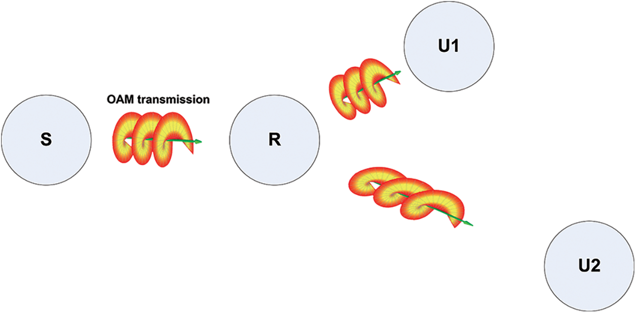
Figure 1: OAM-based cooperative NOMA network system model
We assume that the source always has sufficient information (i.e., it is saturated) to send to relays in all time slots. Due to path loss and shadowing, we assume that the source and destination are not directly connected.
The data rate is fixed at the value
The channel state information at all receivers is assumed to be available. At time slot
where
The channel gains
The system throughput depends on the channel outage; hence we first describe the outage analysis of the cooperative NOMA network. In ordinary transmission networks, an outage occurs if the link capacity is less than the target data rate. Since NOMA is applied from R to users, the relay R needs to have the packets of the two users prior to applying NOMA. In the literature, this is done by two approaches: adding a buffer to R which lengthens the system delay waiting for the two packets to become available at R. The second approach is considering NOMA not applicable unless the link between S and R supports the transmission of the two packets simultaneously, so double transmission rises the outage probability of S to R link to (see [16,17]):
On the other hand, for the R to U1 and U2 links, NOMA can be applied to transmit packets to the two users simultaneously. The superimposed NOMA symbol at R is given by
where
where
Similar to the procedures in [16,17], the condition for finding
Equivalently, if
The probability that (8) or (9) are satisfied to support NOMA is
where
OAM wave of order
the exponential term (
The propagation of OAM wave in space is determined by the paraxial Helmholtz equation:
where
where
Fig. 2 shows the transversal spatial distributions of Bessel–Gaussian waves at different OAM orders. All distances in the figure are normalized to
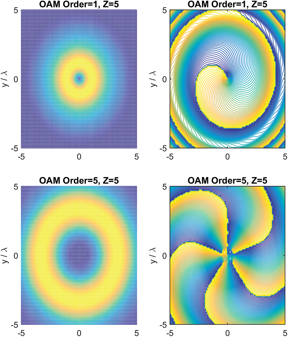
Figure 2: The upper two images show the field spatial amplitude distribution (left). The phase fronts of OAM order = 1 (right). Similarly, OAM order = 5 is shown in the lower two images
3 Simulation Experiments Results
This section presents the simulation experiments results to justify the proposed OAM-based cooperative NOMA system analysis and design. In addition, this section provides performance comparisons between the proposed system and the available related solutions in [14,17]. In the simulations, we assume that the noise variance (
Fig. 3 shows the impact of changing the OAM order on the proposed system throughput. In this experiment, the size of the receiving aperture is selected to match the maximum intensity radius of a certain OAM order (the impact of mismatched size and OAM order on the system throughput is shown in Fig. 4). A receiver consists of a sufficient number of antenna elements (e.g., short dipoles) distributed around a circular circumference (see [12]). It is obvious that the higher the OAM order is the better, especially at high SNR. For instance, at 5 dB (low SNR) the difference between the system throughput at OAM order = 1 and OAM order = 5 is almost 3 packets per time-slot, while this difference is enlarged to 4 packets per time-slot at 20 dB SNR. However, the number of practical OAM orders is limited due to three challenges: the complexity of the receiver, the decrement in the received power and the non-pure rotating phase of large number of OAM orders [12]. On the other hand, the number of users in NOMA technique is limited due to the complexity of SIC design [4].

Figure 3: The proposed OAM-based cooperative NOMA system throughput at different OAM orders

Figure 4: The impact of different receiving aperture sizes on the proposed OAM-based cooperative NOMA system throughput where OAM order = 5
As mentioned above, matching the receiving aperture to the maximum intensity radius of the OAM order maximizes the system throughput. In Fig. 4, OAM orders = 5, if a smaller receiving aperture size 2 is used, the system throughput degrades proportional to SNR, for example, the degradation is almost 3 packets per time-slot at 20 dB compared to using the optimal size i.e., 5.
As in [14], different percentages of the maximum received power (thresholds) have to be considered in order to achieve higher throughputs. Examples of different received power thresholds are shown in Fig. 5. The received power decreases as the OAM order increases. However, the received power decrement can be eased with the right receiver size, which boosts the system throughput. Because the throughput is the summation over all throughputs from every order with received power passing the threshold value.

Figure 5: Different percentages of the maximum received power (thresholds)
It can be observed that lowering the threshold makes the reception less impeded and allows higher OAM orders, therefore, higher throughput is achieved at lower thresholds. This is clearly shown in Fig. 6, the throughput at 10 dB SNR is 4 packets per time-slot higher at 20% threshold than at 90% threshold. The distinction between different thresholds is weekend at high SNR, for example, it is trimmed to 3 packets per time-slot at 20 dB SNR, because raising the SNR helps OAM orders pass the high threshold (i.e., 90%) which enhances the throughput at high thresholds.

Figure 6: The significance of reducing the received power threshold on the system throughput with 5 OAM orders
In [14], the cooperative OAM with 5 OAM orders is compared to the ordinary cooperative NOMA with 5 users. Fig. 7 shows a comparison between these two systems and the proposed OAM-based cooperative NOMA system. The results show the throughput superiority of the proposed system compared to two of the promising solutions for 5G applications. The proposed system almost doubles the throughput of the cooperative OAM which in turn outperforms the ordinary cooperative NOMA. It can be seen from the figure that the cooperative OAM has the highest throughput at very low SNR (

Figure 7: Throughput comparison among the proposed OAM-based cooperative NOMA, the cooperative OAM and the ordinary cooperative NOMA

Figure 8: Outage probability comparison between the proposed OAM-based cooperative NOMA and the ordinary cooperative NOMA
This paper proposes an OAM-based cooperative NOMA solution for future demanding applications such as tactile internet (the next generation of IoT). The throughput of the proposed system is proportional to the OAM orders and the number of users, higher OAM orders is suitable with larger size receiver and with cooperation solutions. The received power threshold has a noticeable impact on the system throughput especially at low SNR. In general, lower power received thresholds achieve higher throughputs. Furthermore, OAM transmission has a positive impact on NOMA by lowering its outage probability. As a result, the proposed OAM-based cooperative NOMA outperforms the separated using of OAM in cooperative OAM and NOMA in ordinary cooperative NOMA.
Funding Statement: The authors received no specific funding for this study.
Conflicts of Interest: The authors declare that they have no conflicts of interest to report regarding the present study.
References
1. J. G. Andrews, S. Buzzi, W. Choi, S. V. Hanly, A. Lozano et al., “What will 5G be?,” IEEE Journal on Selected Areas in Communications, vol. 32, no. 6, pp. 1065–1082, 2014. [Google Scholar]
2. Z. Ding, M. Peng and H. V. Poor, “Cooperative non-orthogonal multiple access in 5G systems,” IEEE Communications Letters, vol. 19, no. 8, pp. 1462–1465, 2015. [Google Scholar]
3. L. Lv, J. Chen and Q. Ni, “Cooperative non-orthogonal multiple access in cognitive radio,” IEEE Communications Letters, vol. 20, no. 10, pp. 2059–2062, 2016. [Google Scholar]
4. H. S. Ghazi and K. W. Wesołowski, “Improved detection in successive interference cancellation NOMA OFDM receiver,” IEEE Access, vol. 7, pp. 103325–103335, 2019. [Google Scholar]
5. M. Alkhawatrah, Y. Gong, O. Aldabbas and M. Hammoudeh, “Buffer-aided 5G cooperative networks: Considering the source delay,” in Proc. of the 3rd Int. Conf. on Future Networks and Distributed Systems (ICFNDS ’19), New York, NY, USA, Association for Computing Machinery, Article 13, pp. 1–6, 2019. [Google Scholar]
6. A. Bletsas, H. Shin and M. Win, “Cooperative communications with outage-optimal opportunistic relaying,” IEEE Transactions on Wireless Communications, vol. 6, no. 9, pp. 3450–3460, 2007. [Google Scholar]
7. A. Nosratinia, T. Hunter and A. Hedayat, “Cooperative communication in wireless networks,” IEEE Communications Magazine, vol. 42, no. 10, pp. 74–80, 2004. [Google Scholar]
8. A. Sendonaris, E. Erkip and B. Aazhang, “User cooperation diversity. part I. system description,” IEEE Transactions on Communications, vol. 51, no. 11, pp. 1927–1938, 2003. [Google Scholar]
9. Z. Ding, H. Dai and H. V. Poor, “Relay selection for cooperative NOMA,” IEEE Wireless Communications Letters, vol. 5, no. 4, pp. 416–419, 2016. [Google Scholar]
10. M. Alkhawatra and N. Qasem, “Improving and extending indoor connectivity using relay nodes for 60 GHz applications,” International Journal of Advanced Computer Science & Applications, vol. 51, no. 11, pp. 427–434, 2016. [Google Scholar]
11. B. Thidé, H. Then, J. Sjöholm, K. Palmer, J. Bergman et al., “Utilization of photon orbital angular momentum in the low-frequency radio domain,” Physical Review Letters, vol. 99, no. 8, pp. 087701-1–4, 2007. [Google Scholar]
12. S. M. Mohammadi, L. K. Daldorff, J. E. Bergman, R. L. Karlsson, B. Thidé et al., “Orbital angular momentum in radio—A system study,” IEEE Transactions on Antennas and Propagation, vol. 58, no. 2, pp. 565–572, 2010. [Google Scholar]
13. B. Mohammadi, J. Nourinia, C. Ghobadi, F. Alizadeh and M. Karamirad, “Wideband sub-wavelength orbital angular momentum reflectarray antenna,” in 5th Conf. on Knowledge-Based Engineering and Innovation (KBEI-2019), Tehran, Iran, pp. 869–873, 2019. [Google Scholar]
14. M. Alkhawatrah, A. Alamayreh and N. Qasem, “Cooperative relay networks based on the OAM technique for 5G applications,” Computer Systems Science & Engineering, in press. [Google Scholar]
15. Z. Wei, J. Guo, D. W. K. Ng and J. Yuan, “Fairness comparison of uplink NOMA and OMA,” in 2017 IEEE 85th Vehicular Technology Conf. (VTC Spring), Sydney, Australia, pp. 1–6, 2017. [Google Scholar]
16. M. Alkhawatrah, Y. Gong, G. Chen, S. Lambotharan and J. A. Chambers, “Buffer-aided relay selection for cooperative NOMA in the internet of things,” IEEE Internet of Things Journal, vol. 6, no. 3, pp. 5722–5731, 2019. [Google Scholar]
17. Q. Zhang, Z. Liang, Q. Li and J. Qin, “Buffer-aided non-orthogonal multiple access relaying systems in Rayleigh fading channels,” IEEE Transactions on Communications, vol. 65, no. 1, pp. 95–106, 2017. [Google Scholar]
18. J. Durnin, “Exact solutions for nondiffracting beams. I. The scalar theory,” Journal of the Optical Society of America A, vol. 4, no. 4, pp. 651–654, 1987. [Google Scholar]
19. D. Lahaye, J. Tang and K. Vuik, “Modern solvers for Helmholtz problems”. Birkhäuser, 2017. [Online]. Available: https://link.springer.com/book/10.1007/978-3-319-28832-1. [Google Scholar]
20. P. L. Greene and D. G. Hall, “Diffraction characteristics of the azimuthal Bessel-Gauss beam,” Journal of the Optical Society of America A, vol. 13, no. 5, pp. 962–966, 1996. [Google Scholar]
Cite This Article
 Copyright © 2023 The Author(s). Published by Tech Science Press.
This work is licensed under a Creative Commons Attribution 4.0 International License , which permits unrestricted use, distribution, and reproduction in any medium, provided the original work is properly cited.
 Downloads
 Citation Tools