
 Submit a Paper
 Propose a Special lssue
 Open Access
ARTICLE
Voice Guidance System for Color Recognition Based on IoT
1 Department of Electrical Engineering, National Chin-Yi University of Technology, Taichung, 411030, Taiwan
2 Department of Information Technology, Takming University of Science and Technology, Taipei City, 11451, Taiwan
* Corresponding Author: Sung-Jung Hsiao. Email:
Computer Systems Science and Engineering 2023, 45(1), 839-855. https://doi.org/10.32604/csse.2023.030408
Received 25 March 2022; Accepted 13 May 2022; Issue published 16 August 2022
 View Full Text
 Download PDF
Abstract
We often need to identify the colors of such objects as buildings, clothing, photos, and traffic signs in everyday life. Some people cannot distinguish among such colors. This study proposes a method to help people, including colorblind people, identify colors. We establish a platform for color identification that is connected by the Internet of Things (IoT). The Espressif Systems 32 (ESP32) single chip is connected to a Wi-Fi communication network to transmit data to the color identification platform. The system interface is displayed in the form of color code and color name display. The speech synthesis module Speech Synthesizer Node 6288 (SYN6288) is used to broadcast color-related information. Since there are many color conversion technologies in modern times, or other color recognition methods are not applicable to the guide-blind function. Therefore, the authors use the method of reading out color-related information to directly enable colorblind people to conveniently identify the colors of objects. After experiments: the accuracy of various colors, the accuracy of environmental impact, the comparison of the original sensing experiment and the effect of adding interference light sources, the time required for color sensing to identify various colors, and the interference test results of any color light source, it is proved that the research mentioned in this research. The proposed method can not only improve the rate of recognition of the system in different environments, but can also accurately identify a variety of colors. The platform is integrated with the IoT to allow users to quickly monitor the displayed data.Keywords
Research on color vision is originated in the 19th century when trichromatic vision theory was proposed by British scientist Thomas Young and the German physicist Hermann von Helmholtz. It explained that the three cones of the retina are preferentially sensitive to blue, green, and red colors. In 1872, however, a theory of complementary processing was proposed by a physiologist, Ewald Hering, stating that the visual system interprets colors in a resistive way: red to green, blue to yellow, and black to white. The basic elements of color are hue, lightness, and chroma. Hue is the appearance of the color, lightness is its lightness or darkness, and chroma is the saturation of the color. More colors can be derived by manipulating these elements. The three primary colors of light are red, blue, and green, and are referred to as Red, Green and Blue (RGB). The color codes used for these colors on the computer screen are each composed of eight bits, for a total of 24 bits, and the RGB color code of 0~255 represents the intensities of the three colors of red, blue, and green. If the intensity of red among the three colors is the highest (i.e., the RGB color code is 255, 0, 0), the screen displays red; if the intensity of blue is the highest (i.e., the RGB color code is 0, 255, 0), it displays blue. Green is displayed if it has the highest intensity (that is, the RGB color code is 0, 0, 255). If all three colors have their highest intensities (that is, the RGB color code is 255, 255, 255), the screen displays white. The TAOS Color Sensor 3200 (TCS3200) color sensor module is used in experiments to identify color [1]. Color blindness, also known as Color Vision Disorder (CVD), makes it impossible for patients to distinguish among certain colors, because of which they cannot derive color-sensitive information from contexts. Color blindness is further divided into red–green color blindness, blue–yellow blindness, and total color blindness. People with red–green color blindness cannot distinguish between shades of red and green, but can see shades of blue, yellow, black, and white; the opposite is true for those afflicted with blue–yellow blindness. Achromatopsia is the most severe form of color vision impairment, and people suffering from it can see only shades of black and white. A total of 8% of men and 0.5% of women in the world are red–green colorblind. Of them, about 6% have trichromatic vision abnormalities, 2% have dichromatic achromatopsia, and very few suffer from achromatopsia. About 0.00001%, such as Fig. 1 is a visual image without color blindness, red–green color blindness, blue–yellow blindness and total color blindness [2].

Figure 1: Visual images from the perspectives of people with varying degrees of colorblindness: (a) no colorblindness, (b) red–green blindness, (c) blue–yellow blindness, (d) full color blindness
A pressing problem in current research on color recognition is the multi-functional method of presentation. This research uses voice combined with functions of the Internet of Things (IoT) to comprehensively consider all possible situations to solve this problem. The blind guide function is strengthened and can be applied to the industry. This offers the best solution for such problems as the accuracy of identification of color. Many industries often apply color identification when performing measurement-related tasks. The basic element in architectural design is color matching. The method of color identification proposed in this study can be used to avoid errors in color in design. The voice guidance system can accurately measure and recognize colors, and provides the requisite information on the system interface. The voice IoT-based guidance function developed here can be used to detect colors of the ground for guidance. The voice function can enable the blind to listen to color-related information. CVD patients cannot recognize traffic signs. The recognition of color afforded by the proposed system can help them do so to ensure their safety. The authors consider various methods to improve the situation of CVD patients and blind people by thinking from their perspective, and examine the accuracy of identification of various colors, environmental impacts on this accuracy, the effect of adding a light source as interference, and the time needed for recognition. Taking into account the light source interference, on the one hand, it prevents the danger of environmental influence, and on the other hand, it can correctly perform color recognition without light source interference, so that they can enjoy the same convenience as much as possible to change the quality of life.
Most methods to enable vision-impaired people to identify colors offer the same general solution for all patients, even though each patient has a different ability to recognize colors [2]. Fig. 1 shows simulated visual images from the perspectives of people with no color blindness, red–green color blindness, blue–yellow blindness, and total color blindness. Because the accuracy of color recognition is limited by the mechanics of the human eye, this study proposes a method that uses the color sensor TCS3200 to replace manual color recognition [3]. The Espressif Systems 32 (ESP32) is connected to a Wi-Fi network, and data on color recognition, such as RGB color codes, are stored and uploaded to the ESP32 web server to establish a platform for color recognition. Instead of manually solving problems, such as unrecognizable colors, the proposed platform can be applied for color guidance for the blind. The proposed platform conforms to the three-layer architecture of the IoT, which enables the detection sensor to transmit data through the Internet. Data analysis is performed by the monitoring platform for color sensing. The proposed system can be used on any object and in any environment to help those with colorblindness.
Most applications of the color sensor TCS3200 pertain to the industry and transportation. From the perspective of the experimental system, this study considers applications for the introduction and recognition of color, and IoT technology. For a voice guidance system for color recognition, it is necessary to understand the RGB color code. Users can familiarize themselves with the colors corresponding to hue-related data in addition to identifying the color. Being able to sense any item with a color sensor can also allow for the use of the system in a variety of contexts in daily life. The IoT technology allows users, who hitherto were able to use only the identification system, to now control its equipment as well. The data can then be analyzed on the network platform.
One of the case studies on color perception involves extracting the given image and processing it through a color transformation algorithm. This allows CVD patients to see the correct color. Another method uses RGB-to-Hue, Saturation, and Value (HSV) conversion technology, and involves converting an image captured in the RGB color space into the HSV color space such that the colors can be recognized. However, these methods are not suitable for blind people. The proposed method, on the contrary, allows for color to be obtained directly through the website without using color conversion technology, and voice guidance is suitable for CVD patients as well as blind people to receive color information.
Color recognition is widely used in modern production, including for materials, industrial automation, remote sensing technology, image processing, product quality inspection, and some fuzzy detection technologies that require color detection. In many applications, it is often not necessary to accurately determine the spectral composition of colors but only to distinguish between them. Color is characterized by three basic principles: hue, saturation, and brightness. Hue represents the wavelengths reflected by light that characterize different colors, and saturation is the purity of the color. As any color is mixed with white, the greater its ratio is, the higher is the color saturation. Brightness describes the lightness or darkness of the color, which is similar to the definition of lightness. However, it considers depth in addition to light and shade.
If any color is mixed with black, the greater the proportion of black is, the lower is the brightness of the final color [1]. The module required for color recognition is a color-sensitive measuring module. Its principle is to use a color sensor to convert light signals into current for pre-processing, followed by Analog/Digital (A/D) conversion. Finally, the digital signal is given to the microcontroller for processing. The color sensor detects the color of a given object by comparing it with the reference color trained in pre-processing. The result of detection can be presented in different ways. Sensors used to identify colors can be classified into RGB color sensors and color mark sensors. We use RGB color sensors in this study. They can distinguish between similar colors and tones, and present the results of color detection by measuring the ratio of light reflectance of the three primary colors that constitute the color of the object. Owing to the high precision of this method of color detection, the RGB sensor can accurately distinguish among very similar tones [4].
Color images are usually stored and expressed in RGB. Because non-linear transformations of the color space lead to the loss of information in the original image such that it renders the transformed image sensitive to noise, edge detection in the RGB color space can be used to obtain close to the best results. Any color can be obtained in the RGB color space by changing the ratios of the three color channels of red (R), green (G), and blue (B), and adding them. This can be expressed as follows [5]:
I is any color, R is red, G is green, B is blue, and a, b, and c are the coefficients of R, G, and B, respectively. The value of I can be changed by changing the values of a, b, and c. The RGB color space can also be described by a Three-Dimensional (3D) cube. Fig. 2a shows a schematic diagram of the 3D RGB color space. Red, green, and blue are located at (255, 0, 0), (0, 255, 0), and (0, 0, 255), respectively. When values of the three RGB color codes drop to the lowest point, their coordinates are (0,0,0), representing black. When the three RGB color codes have their highest values, their coordinates are (255, 255, 255), and the color is white. Therefore, the three primary colors are synthesized into white light; otherwise, there is no source of light for color.

Figure 2: (a) Schematic diagram of the 3D color space of RGB (b) Triangle diagram of R, G, and B coefficients (c) Basic architecture of the IoT
2.1.2 Edge Principle of Color Similarity Expressed by Triangles
Any color I is a point in the coordinates of the cube. When the coefficients of R, G, and B are changed, the value of the coordinates of I changes, which in turn changes the value of I. We define values of the coefficients R, G, and B corresponding to the three sides of a triangle, and the relationship between the color and the triangle, any change in the R, G, B values can change the color, such as Fig. 2b is the R, G, B coefficient values. As shown in the schematic diagram of the triangle, the sides X, Y, and Z represent
We use the socket method to set-up a simple Transmission Control Protocol (TCP) server on the ESP32, and use the TCP test software on the computer platform to execute the remote control Input/Output (I/O) function. The steps are as follows: First, we identify the connection of the experimental circuit according to color and import some required modules. We set the mechanism of Wi-Fi networking and design a timeout mechanism. Once the connection is successful, the system displays the relevant network information. After establishing the Wi-Fi object, we gain Internet access to obtain an IP. We then enter the TCP connection process and set the TCP communication. After initializing the socket, we set the host Internet Protocol (IP) and service port, and limit the number of TCP connections to one. Finally, the system remembers the number of Short Message Service (SMS) messages received. After setting-up the TCP connection, we wait for the connection of the remote client. After another successful TCP disconnection, it restarts and waits for another connection.
The systems start the blocking mode and waits for the client to connect to the TCP server. Once the server receives the connection request from the client, the system creates new socket object and client address information for this connection, and finally conducts a test circuit experiment [7]. The socket is a JavaScript communication library for real-time web applications that uses WebSocket as the main transmission protocol, and plays an important part in TCP/IP transmission to enable real-time two-way communication between the server and the client. The advantage of socket Input/Output (I/O) is that it automatically selects a suitable two-way communication protocol, and only the programmer needs to understand the concept of the communication terminal [8]. Socket I/O is divided into two parts: a client-side library executed in the browser and a server-side library for Node.js, both of which have almost the same API. Node.js is an open-source and cross-platform execution environment capable of running JavaScript on the server side. Most of the basic modules of Node.js are written in the JavaScript language [9]. Before the advent of Node.js, JavaScript was typically used as a user-side programming language, and programs written in JavaScript were often executed on the user’s browser. “Application Programming Interface (API)” stands for the application programming interface, a computing interface that defines the interaction between multiple software and the intermediary software [10].
The Internet of Things (IoT) is a system in which devices, machines, and other functions are transmitted through a network and are interrelated without requiring interaction between people, or between people and devices. The fields of application of the IoT include smart homes and offices, smart factories, smart electronic products, healthcare and transportation, and logistics. The basic architecture of the IoT is shown in Fig. 2c. It can be divided into three layers. From the bottom to the top are the sensing layer, the network layer, and the application layer. The application layer can be further divided into a platform tool layer and an application service layer [4].
Sensing layer: The sensor sends data to the network layer through TCP/IP, Universal Serial Bus (USB), Radio Frequency Identification (RFID), ZigBee, Bluetooth, and/or other transmission protocols.
Network layer: It is further divided into the wireless telecommunication network and the wireless data network. The wireless telecommunication network is mainly used in mobile communication, such as voice communication, video and other multimedia functions. Wireless data network is further divided into the wide area network, Wireless Local Area Network (WLAN), and mobile device network. A Wide Area Network (WAN) is a remote network that connects LANs in different regions or urban networks for communication. A WLAN uses radio waves or electric and magnetic fields as medium for data transmission. The most common standard for the wireless local area network is the 802.11 series of standards defined by the IEEE. Mobile device networks, mobile networks, and Wi-Fi can provide communication and network services on it, thus rendering mobile phones the terminal devices of the Internet [5].
Application layer: The main technologies involved in this layer include cloud computing and large data analysis. Cloud computing can process a large amount of data in a short period and upload them centrally to the cloud host. It can reduce the network delay of applications for a better economic scale. Big data analysis involves processing a large amount of data through cloud computing, and requires advanced computing technology [6].
Wi-Fi, also known as the “wireless hotspot” or the “wireless network,” is a trademark of the Wi-Fi Alliance and a wireless local area network technology of the IEEE 802.11 standard. Wi-Fi specifications are the strictest around. After all, Wi-Fi manufacturers invest the most money and, relatively, have the largest market application base. Its specifications include a low frequency of 2.4 GHz, a high frequency of 5 GHz and an ultra-high frequency of 60 GHz that cover a wide range of applications and devices. Compared with other wireless communication technologies, Wi-Fi has the characteristics of a longer transmission distance and a higher transmission rate.
Wi-Fi has also developed toward low power consumption in recent years. Wi-Fi products are rigorously tested by an independently authorized test laboratory of the Wi-Fi Alliance. Once the products pass the test, manufacturers or sellers are authorized to use the Wi-Fi logo, Wi-Fi Certified logo, and related trademarks. The Wi-Fi Alliance uses the term “Wi-Fi Certified” to refer to such certified products. Wi-Fi is often used in the IoT, and the network implemented in this study uses Wi-Fi for wide-area signal transmission [4,11].
The Long Short-Term Memory (LSTM) is a time-based Recurrent Neural Network (RNN), a neural network containing LSTM blocks that may be described in reference to the literature or other materials, such as an intelligent network unit. Because it can memorize values for indefinite lengths of time, there is a threshold in the block that determines whether the input is important enough to be remembered and whether it can be output. LSTM-related expressions are shown in Eqs. (5)–(8), where
Word2vec was proposed by Tomas Mikolov et al. in 2013. It is a model that generates word vectors for training to reconstruct linguistic word texts. By learning a large amount of text data, words can be represented by mathematical vectors to represent their semantics. The word2vec model can map each word to a vector to represent the relationship between words. After embedding words into a space, words with similar semantics can be rendered more closely in the semantic space.
Fig. 3a shows the hardware architecture of the proposed system. It includes three chips: an ESP32 chip module, a TCS3200 color sensor, and a Speech Synthesizer Node 6288 (SYN6288) speech synthesis module. Once the system has been connected to the Wi-Fi network, the ESP32 chip module receives the results of identification of the TCS3200 color sensor and transmits the data to the color identification platform. The data are converted into voice on the platform, and the voice is played through the voice synthesis module SYN6288.

Figure 3: (a) System architecture (b) flowchart of voice guidance system for color recognition
The ESP32 chip module is commonly used in related research, and the ESP8266 chip module was the most commonly used module prior to this. The ESP32 is more powerful, and has advantages over the ESP8266 in terms of power consumption, speed of program execution, and expansion of the interface. The working current of ESP32 is 5 µA, compared with 20 µA for the ESP8266, and it executes programs twice as quickly. ESP32 has more Bluetooth and General-Purpose Input/Output (GPIO) pins to provide more I/O connections. The TCS3200 color sensor is the main axis in the experiment, and the main task is object recognition.
The pins of TCS3200 were controlled by S0, S1, S2, S3, Vcc, and the Ground (GND). The pins S0 and S1 were used to control the output frequency, and S2 and S3 were set for the photodiode in the TCS3200. This setting was determined by the type of photodiode on the original specification sheet, that is, it was set by the red, green, and blue colors as well as the transparent filter specifications. The speech synthesis module SYN6288 performed the speech function of the guidance system for color recognition. The voice module could play only recorded audio content. The “record” button was pressed and held to start recording the voice. The recording stopped when the button was released, and was played back when the “play” button was pressed. The speech synthesis module used the text-to-speech method to play.
Fig. 3b shows a flowchart of the voice guidance system for color recognition. As long as an object reflected white light, its color could be recorded. This system used the TCS3200 color sensor to identify the color of the surface of the object. The identification strategy involved calculating the ratios of red, green, and blue. The code was written in Arduino Integrated Development Environment (IDE). The TCS3200 sensor was connected to the ESP32 chip module and the program was uploaded to the chip. We designed various experimental conditions for the color recognition task and calculated the accuracy of the results. The steps of the program were as follows: The data were first sent to the database as required by the website. We then defined the pins of S0, S1, S2, S3, Output, and ESP32, created the transmission folder as the system’s data holder, and controlled the Light-Emitting Diode (LED) lights as well as the input and output pins of the TCS3200 such that they operated continuously. We then waited for the connection to succeed. Following this, we connected the ESP32 to Wi-Fi; if the connection was successful, we turned on the control LED and wrote the Wi-Fi Service Set Identifier (SSID) to the socket I/O communication library along with the assigned IP location. We then entered the variable for the connection path, and defined a name and value for each dataset.
According to the pins S0 and S1 given in the table for the scaling specifications of the output frequency, the scaling of the output frequency was set to 20% in this study. We obtained the RGB color codes as an array from the TCS3200 color sensor. The system read the frequency and stored it according to the type of photodiode in the TCS3200. We set the scaling values of S2 and S3 given in the specification table, and the frequency and brightness of the sensor. The obtained value represented the frequency in the given RGB model. The system platform also provided the RGB value of the color sensor to allow the user to set the display format. Finally, the color-coded data on the monitor were received by the ESP32. We connected the ESP32 to the website of the color recognition platform, established in this experiment via a Wi-Fi network, and uploaded the recognition data to the socket I/O communication library.
This system set-up the ESP32 is web server in the socket I/O communication library. The color identification platform was established and finally displayed color-related information, such as the color code and color name. The user could then start operating the webpage of the platform. Once the platform had been connected to the network, the IP address was input to the website. The user could then access the webpage and press the color identification button to start the experiment. The system used ESP32 to control the speech synthesis module SYN6288 to read the data, convert them into speech, and express color-related information by playing the speech.
The TCS3200 color sensor can identify the color of objects. It senses the three primary colors, and can output three values of RGB as well as the color difference of the object. The TCS3200 is manufactured by TAOS Company, has a TAOS TCS3200 RGB sensor chip and four white LED lamps, and uses an eight-pin Small Outline Integrated Circuit (SOIC) surface-mounted package. It is an integrated circuit that converts the color of light into frequency values, and the sensor can then record data on up to 25 colors. The photodiodes were arranged crosswise, and diodes of the same color were connected in parallel and evenly distributed. A total of 64 photodiodes were integrated on a single wafer and divided into four types: namely, red, green, blue, and transparent filters. The red, green, and blue filters had 16 photodiodes, and the transparent filter could transmit all light [12,13]. The TCS3200 color sensor is shown in Fig. 4a.
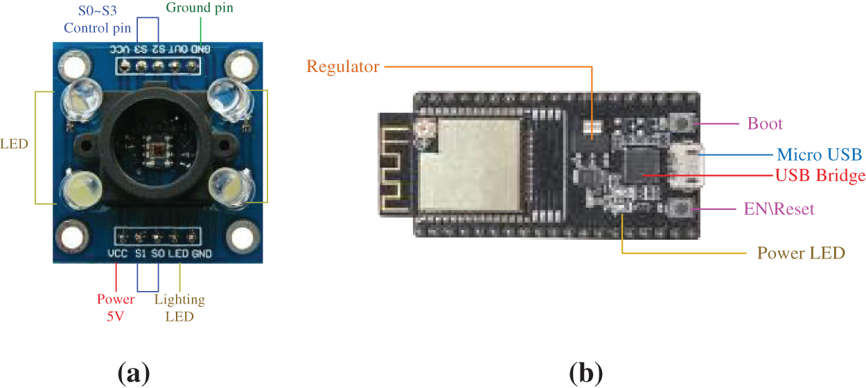
Figure 4: (a) TCS3200 color sensor (b) ESP32 single-chip microcontroller (c)
The output frequency was scaled by two logic inputs S0 and S1. An internal optical frequency converter generated a pulse train with a fixed pulse width. Scaling was accomplished by internally connecting the output of the converter’s pulse train to a series of frequency dividers. The divided output was a square wave with a 50% duty cycle and relative frequencies of 100%, 20%, and 2%. Because the output frequency was divided by counting the pulses of the internal frequency of the system, the final output of the period represented the average of multiple periods of the system’s frequency. When light was projected on the TCS3200 sensor, the type of photodiode could be selected through a certain combination of S2 and S3. For example, Tab. 1 shows the reference values for setting the type of photodiode in TCS3200 and Tab. 2 shows the setting for scaling the frequency [13].


The ESP32 is manufactured by Espressif Technology, a global Artificial Intelligence & Internet of Things (AIoT) Chip Company. It is a low-power single-chip microcontroller that uses the Wi-Fi or Bluetooth communication network to obtain and transmit the data. The network protocol is fully Wi-Fi 802.11b/g/n/e/i and Bluetooth 4.2 compliant. The ESP32 series uses the Tensilica Xtensa LX6 microprocessor, and has a highest frequency of 240 MHz, a computing power of up to 600 DMIPS, including dual-core and single-core variants, a built-in antenna switch, an RF converter, a power amplifier, a low-noise receiver amplifier, filters, and power management modules. Compared with the previous generation of the ESP8266 chip module, the ESP32 chip module has more memory. Its integrated tuning cache helps improve system performance and optimize storage, and it can be used as a stand-alone application or as a host Micro Control Unit (MCU) device. The ESP32 also integrates a wealth of analog sensing and digital interfaces, has an ultra-low-power RF architecture, and uses patented power-saving technology that can prolong battery life. The ESP32 chip microcontroller is shown in Fig. 4b [14].
Fig. 5a shows pins of the ESP32 single-chip microcontroller. It has two power pins, 32 output and input pins (GPIO), three GND pins, and an enable pin (EN). The voltages of its power pins are 5 and 3.3 V. The GND pins are all ground pins, and the enable pin (EN) is used to enable and disable the module. It is enabled when the pin is on “high” and disabled when it is on “low.” The output–input pins (GPIOs) communicate with the LEDs, switches, and other input and output devices. The chip has a total of 16 Analog-to-Digital Converter (ADC) pins to convert analog voltage (sensor output) into digital, including G2, G0, G4, G12, G14, G25~27, G32~36, and G39. There are two Digital-to-Analog Converters (DAC), the G25 and G26 pins, which have a precision of 8 bits. All pins except for the enable pin (EN), power pin, and GND pin can use the Pulse Width Modulation (PWM) function [15].
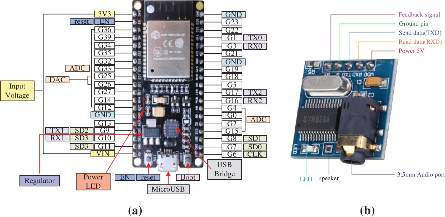
Figure 5: (a) Pin diagram of ESP32 single-chip microcontroller (b)SYN6288 speech synthesis module
The SYN6288 chip module was manufactured in 2010 by Yuyin Tianxia Technology Co., Ltd. It is a speech synthesis module that is used to play Chinese speech, and can support words synthesized by using English letters. It is one of a series of speech synthesis chip modules launched and packaged in SSOP28L. The only disadvantage of this module is that the default speech is a standard female voice, and this cannot be changed. When playing the text, the pronunciation is very mechanical although the articulation is clear. This speech synthesis module is suitable for voice broadcasts, such as bank queuing broadcasts, shopping malls promotions, and station announcements.
The SYN6288 speech synthesis module consists of a 2.2 cm square circuit board. Its structure is as follows:
(1) A small speaker with a diameter of 5.5 cm, resistance of 8 Ω, and power of 0.5 W with five I/O pins can be plugged into the wire connection for voice. The five pins are VDO (Voltage Device Output), RXD (Transmit (tx) Data), TXD (Receive(rx) Data), G(Ground), and BY (Busy/Ready).
(2) VDO is a VCC (Voltage Current Circuit) pin in the broad sense, and is connected to a 3.3 V power supply.
(3) RXD is the data-reading end of the serial port that is connected to the TX of Arduino development board (UNO).
(4) TXD is the data-sending (feedback) end of the serial port connected to the RX of Arduino development board (UNO).
(5) G is the ground pin.
(6) BY is the feedback signal of the chip. A low level indicates that the chip is not in a busy state, and can accept commands and data. A high level indicates that the chip is in a busy state, performing speech synthesis and broadcasting. The SYN6288 speech synthesis module is shown in Fig. 5b [16].
A flowchart of the program of the color recognition system is shown in Fig. 6a. We import the Wi-Fi library, enter the Wi-Fi username and password, set the port number of the web server to 80, define the output variable assigned to the GPIO pin, and set the current time and the last time. The baud rate used in the program was 115200 bps. Following this, the output pins are defined, Wi-Fi is set, and the mode is adjusted to STA mode. We then set the red, blue, and green filter photodiodes to be read as well as the frequency of the read output [17].
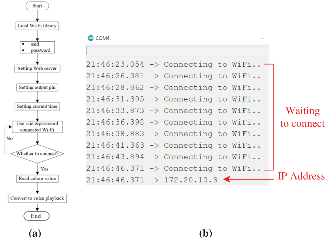
Figure 6: (a) Program of the color recognition system (b) The status of network connection of the monitoring window
The output frequency was scaled to 20%, and the output frequencies of red, blue, and green were scaled according to the specification table. The user observes the transmitted client. If there is a new client connection, the user enters its IP address in the monitoring window. The color recognition web platform can display the fonts and colors of webpages according to the user’s needs, the color data must be set to display, and the color data and the name of the color are broadcast by the ESP32 and the SYN6288 control speech synthesis module in the form of voice. After connecting the system to the Wi-Fi network, the user can open the program monitoring window to observe whether the connection is successful. If it is, the user enters the IP address to access the web interface of the voice guidance system for color recognition on the website platform. This webpage must be in the same local area network as the user. The status of network connection of the monitoring window is shown in Fig. 6b.
4 Analyses of Experimental Results
This study divides the experimental results into two parts. The first consisted of the general results of research and the second featured a new function added based on the results of the first part. Consider the common application of color sensors as an example. Most common points represent color recognition. Most studies have used mechanical equipment, such as robotic arms, to classify items. This study uses the IoT to allow users to understand the given information. When combined with the blind guide, it also provides a voice guidance function that can help the blind listen to the color-related information in various environments. A functional comparative diagram of the experimental results is shown in Fig. 7a.
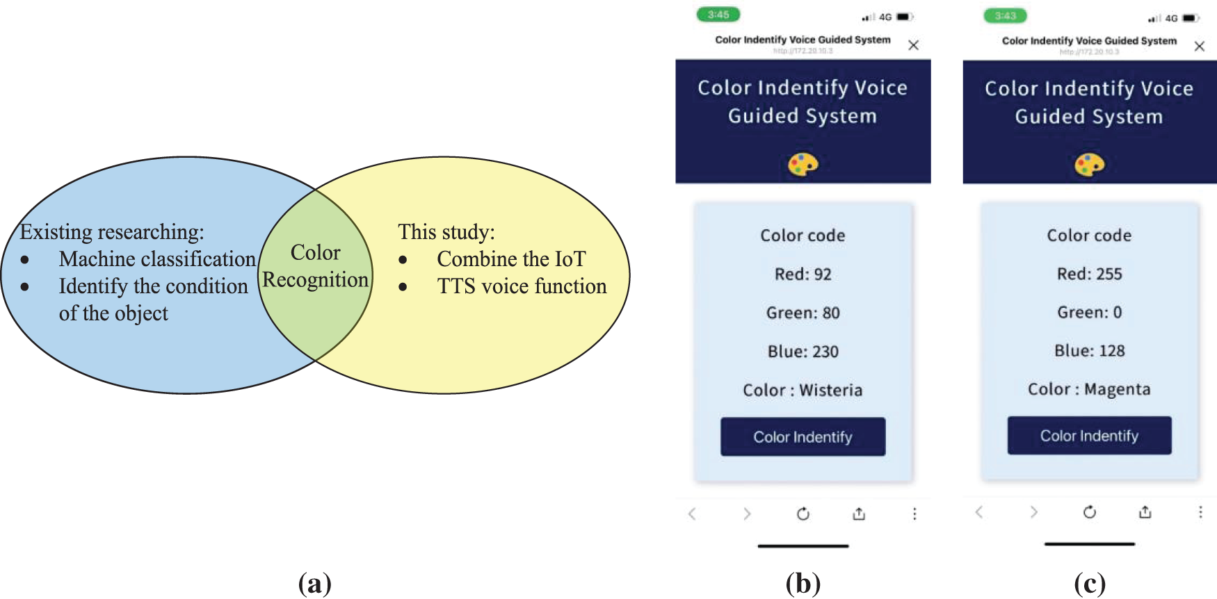
Figure 7: (a) Comparative functional diagram of the experimental results (b)Web interface of the experiment results: recognized color, wisteria; (c) recognized color, pink
Figs. 7b and 7c show the web interface of the experimental results. By taking the color identified in Fig. 7b as an example, the color code is Red: 92; Green: 80; Blue: 230, and the name of the color is wisteria. The color codes identified in Fig. 7c are Red: 255; Green: 0; Blue: 128, and the name of the color is magenta. When the user accesses the webpage, they need to only press the “color identification” button to quickly identify the color, and the color code and name are displayed. When receiving the color code and name, the speech synthesis module SYN6288 transmits this information in time to enable the user to identify the color [18,19].
4.1 Experiments on Average Accuracy of Identification of Various Colors
The average accuracy of identification of various colors by the system is shown in Tab. 3, and Fig. 8a shows a chart of the trend of predictions. The color sensor was tested on 80 items of data. The average accuracy of identification of red (99.02%) was the highest while that of blue was the lowest (91.24%). Some strokes of azure blue were mistaken for green.

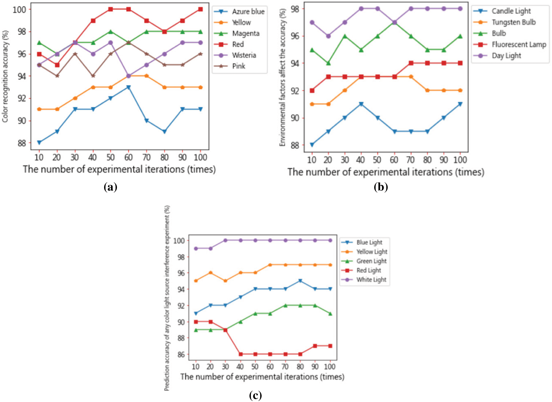
Figure 8: (a) Predictive trend of the proposed system for various colors (b) Predictive trend of the accuracy of the proposed method in the presence of environmental factors (c) Predictive trend of the accuracy of the proposed method in the presence of interference by a light source
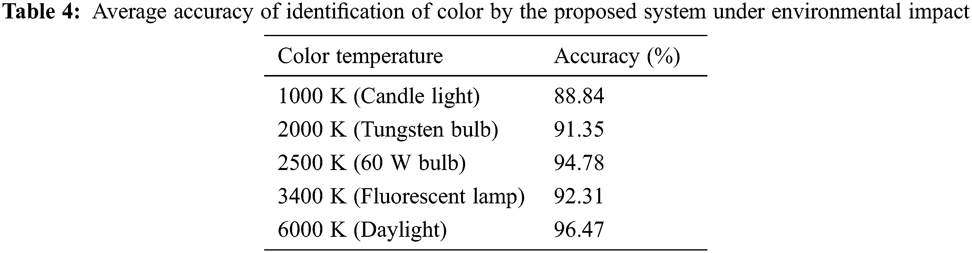
4.2 Color Temperature Experiment Considering Environmental Impact
The accuracy of color sensing is changes with the environmental impact. We thus considered the effects of environmental impact. Sixty tests were carried out to analyze the average accuracy of the proposed system in the presence of environmental impact. Tab. 4 shows the results, and Fig. 8b shows the predictive trend of the average accuracy of the system. Considering the color temperature of the light source in the environment, taking the color temperature of 5600 K as an example, in the sunlight environment with a color temperature of 6000 K, the accuracy is 96.47%, which is in the accuracy is the highest in all tests; on the contrary, under the candle light with a color temperature of 1000 K, the average accuracy is the lowest at 88.84%, and the overall average is 92.68% because the surrounding light is reflected in a dim environment.
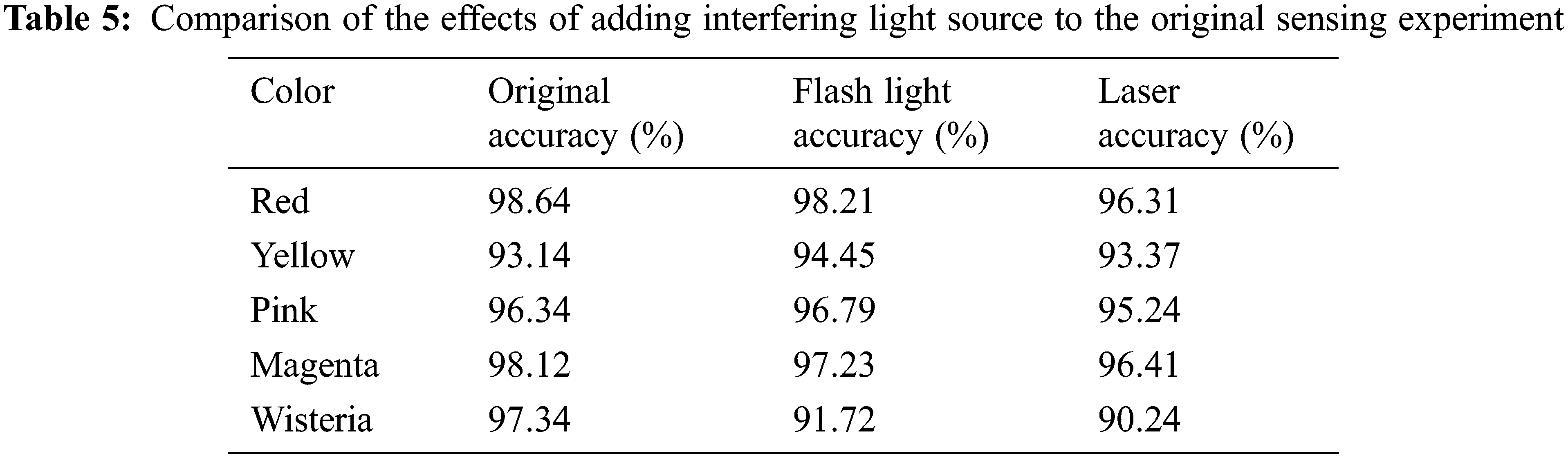
4.3 Sensing Experiment by Adding Interference Light Source
The accuracy of color sensing in different environments is different. The color of objects is observed due to the reflection of light from them. We measured the accuracy of the proposed method in the presence on an interfering light source, such as laser light or a flashing light. The results of the original sensing experiment and those obtained when an interfering light source was added are shown in Tab. 5. When flashing light and laser light were used in irradiation tests, the system had the highest accuracy of recognition for red and the lowest for wisteria.
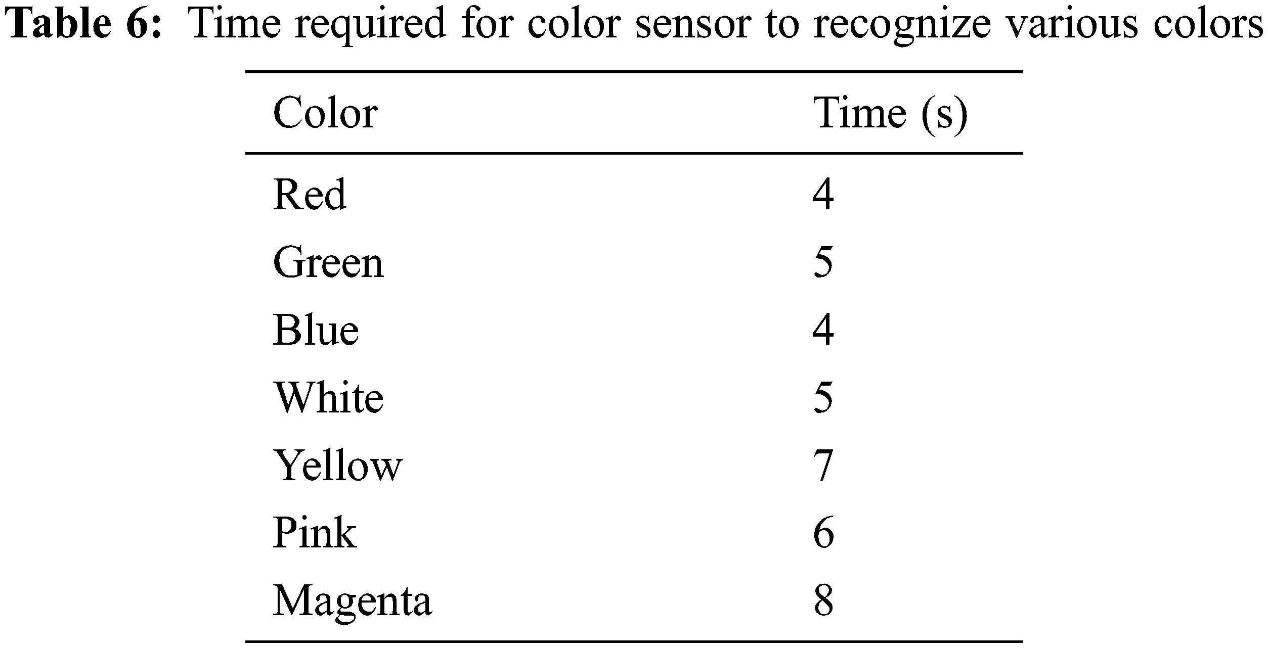
4.4 Experiment on Time Required to Identify Various Colors
The time required by the proposed system to identify various colors is shown in Tab. 6. The basic color recognized by the color sensor is recognized first, and the sensor is finally recognized to recognize other different colors. The time required by the system to recognize white was almost the same as those for red, blue, and green—4~5 s. About 5~6 s were needed to identify other colors, such as yellow and pink. Wisteria required the longest time, 8 s, to identify.
The results of experiments in the presence of an interfering light source are shown in Tab. 7. Fig. 8c shows the predictive trend of the average accuracy of the proposed method in this case.
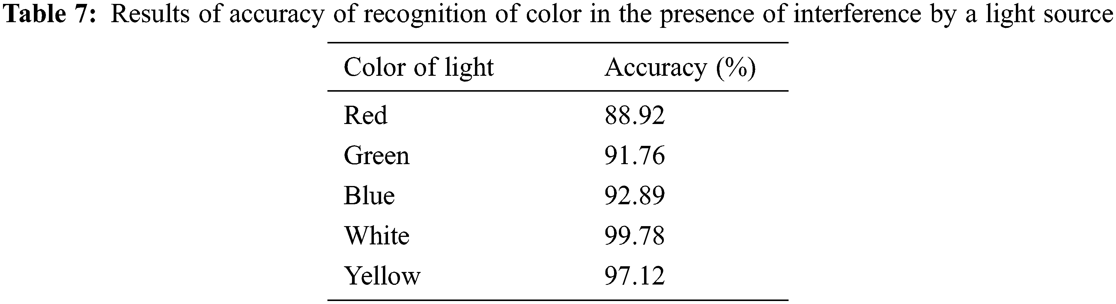
4.5 Identification Experiment Involving Shining a Light on Surface of Object
This experiment involved irradiating the surface of the object with various single-color lights to perform color recognition. Because white is the most common color of the light source, its accuracy of identification was the highest at 99.78%. Green had the lowest accuracy of identification, 90.85%. The system was able to identify red, blue, and yellow light sources with accuracies of 89.87%, 94.68%, and 97.34%, respectively [20–22].
This study proposed a system that uses the TCS3200 sensor to identify color. The control core used the ESP32 chip module to store and transmits data. The aim was to allow the color recognition platform to quickly track color-related information. The system controlled the speech synthesis module SYN6288 through ESP32 and output voice relaying information on the color. In addition to improving industrial manufacturing, this system can help people who cannot recognize colors as well as the blind to identify colors in their environment. The experimental project of this research combined the functions of color sensors to collect and store data, and used the speech synthesis module to voice the name of the relevant color. We also set-up a website and used the Internet of Things to present color-related information for timely visualization on the data platform. The IoT-based color identification platform can be combined with various smart home appliances to help the public in a variety of contexts. Because of the varied applications of the IoT, a combination of sensing modules can enhance the use of the platform and help improve the quality of life of visually impaired people.
One purpose of this study was to simulate the perspective of people who are colorblind, and use a voice guidance system for color recognition to guide them in scenarios where identifying colors is important. We reported a variety of related experiments on the average accuracy of recognition of various colors, the effects of the environment on color recognition, a comparison between the original sensing experiment and the results obtained by adding interference-inducing light sources, the color sensing and identification of various The time required for color and the interference test results of any color light source, etc. The proposed color recognition system can be used in various environments and its color sensor can identify the frequency of any color under any given conditions. We gauged its performance by adding an interference-inducing light source to the testing environment. The system recorded an accuracy of identification of color of up to 99.78%, and could identify the colors of surrounding objects under different color temperatures of light. Even if the color temperature changed, the system could accurately detect and analyze the data. Future work in the area should combine big data with the multi-variable mode of learning of Artificial Intelligence to diversify the functions of the system, and enhance its convenience and ease of use.
Acknowledgement: This research was supported by the Department of Electrical Engineering at National Chin-Yi University of Technology. The authors would like to thank the National Chin-Yi University of Technology, Takming University of Science and Technology, Taiwan, for supporting this research. We thank Cwauthors (https://www.cwauthors.com) for its linguistic assistance during the preparation of this manuscript.
Funding Statement: The authors received no specific funding for this study.
Conflicts of Interest: The authors declare that they have no conflicts of interest to report regarding the present study.
References
1. A. S. Manaf and R. F. Sari, “Color recognition system with augmented reality concept and finger interaction: Case study for color blind aid system,” in Proc. 2011 Ninth Int. Conf. on ICT and Knowledge Engineering, Bangkok, Thailand, pp. 118–123, 2012. [Google Scholar]
2. D. Q. Utama, T. L. R. Mengko, R. Mengko, A. P. Gandasubrata and T. N. Azhar, “RGB color cluster re-coloring algorithm for partial color-blind people,” in Proc. 2017 5th Int. Conf. on Instrumentation, Communications, Information Technology, and Biomedical Engineering (ICICI-BME), Bandung, Indonesia, pp. 219–222, 2017. [Google Scholar]
3. F. Zhang, H. Cheng, W. Sun, Y. Zhang and X. Wang, “Color image edge detection arithmetic based on color space,” in Proc. 2012 Int. Conf. on Computer Science and Electronics Engineering, Hangzhou, China, pp. 217–220, 2012. [Google Scholar]
4. S. Chaudhary, R. Johari, R. Bhatia, K. Gupta and A. Bhatnagar, “CRAIoT: Concept, review and application(s) of IoT,” in Proc. 2019 4th Int. Conf. on Internet of Things: Smart Innovation and Usages (IoT-SIU), Ghaziabad, India, pp. 1–4, 2019. [Google Scholar]
5. X. Wang, F. Lin and Y. Wu, “A novel positioning system of potential WiFi hotspots for software defined WiFi network planning,” in Proc. 2019 16th IEEE Annual Consumer Communications & Networking Conf. (CCNC), Las Vegas, NV, USA, pp. 1–6, 2019. [Google Scholar]
6. A. K. Gupta and R. Johari, “IOT based electrical device surveillance and control system,” in Proc. 2019 4th Int. Conf. on Internet of Things: Smart Innovation and Usages (IoT-SIU), Ghaziabad, India, pp. 1–5, 2019. [Google Scholar]
7. P. Macheso, S. Chisale, C. Daka, N. Dzupire, J. Mlatho et al., “Design of standalone asynchronous ESP32 web-server for temperature and humidity monitoring,” in Proc. 2021 7th Int. Conf. on Advanced Computing and Communication Systems (ICACCS), Coimbatore, India, pp. 635–638, 2021. [Google Scholar]
8. Q. Liu, G. Yang, R. Zhao and Y. Xia, “Design and implementation of real-time monitoring system for wireless coverage data based on WebSocket,” in Proc. 2018 IEEE 3rd Int. Conf. on Cloud Computing and Internet of Things (CCIOT), Dalian, China, pp. 63–67, 2018. [Google Scholar]
9. M. K. Mwila and P. Mbewe, “Design and implementation of a Node.js based communication framework for an unmanned autonomous ground vehicle,” in Proc. 2017 Pattern Recognition Association of South Africa and Robotics and Mechatronics (PRASA-RobMech), Bloemfontein, South Africa, pp. 74–79, 2017. [Google Scholar]
10. M. Mirtsch, J. Kinne and K. Blind, “Exploring the adoption of the international information security management system standard ISO/IEC 27001: A web mining-based analysis,” IEEE Transactions on Engineering Management, vol. 68, no. 1, pp. 87–100, 2021. [Google Scholar]
11. M. Fongbedji, N. Krami and M. Bouya, “Mobile application and Wi-Fi modules for smart home control,” in Proc. 2020 IEEE 2nd Int. Conf. on Electronics, Control, Optimization and Computer Science (ICECOCS), Kenitra, Morocco, pp. 1–4, 2020. [Google Scholar]
12. F. Fattah, D. Indra, S. Mulyana, Y. Salim, I. As’ad et al., “Measurement of iodine levels in salt using color sensor,” in Proc. 2021 3rd East Indonesia Conf. on Computer and Information Technology (EIConCIT), Surabaya, Indonesia, pp. 410–414, 2021. [Google Scholar]
13. G. I. E. Panie and A. B. Mutiara, “Development of robotic arm for color based goods sorter in factory using TCS3200 sensor with a web-based monitoring system,” in Proc. 2018 Third Int. Conf. on Informatics and Computing (ICIC), Palembang, Indonesia, pp. 1–6, 2018. [Google Scholar]
14. A. Zare and M. T. Iqbal, “Low-cost ESP32, Raspberry Pi, Node-Red, and MQTT protocol based SCADA system,” in Proc. 2020 IEEE Int. IOT, Electronics and Mechatronics Conf. (IEMTRONICS), Vancouver, BC, Canada, pp. 1–5, 2020. [Google Scholar]
15. N. Jangamreddy, V. Sethi and S. Pal, “Web-based gesture recognition system for controlling heterogeneous IoT devices using deep learning,” in Proc. 2019 11th Int. Conf. on Communication Systems & Networks (COMSNETS), Bengaluru, India, pp. 700–702, 2019. [Google Scholar]
16. Y. Sun, L. Geng and K. Dan, “Design of smart mirror based on Raspberry Pi,” in Proc 2018 Int. Conf. on Intelligent Transportation, Big Data & Smart City (ICITBS), Xiamen, China, pp. 77–80, 2018. [Google Scholar]
17. S. L. Ching and M. Sabudin, “Website image colour transformation for the colour blind,” in Proc. 2010 2nd Int. Conf. on Computer Technology and Development, Cairo, Egypt, pp. 255–259, 2010. [Google Scholar]
18. W. Sun, G. C. Zhang, X. R. Zhang, X. Zhang and N. N. Ge, “Fine-grained vehicle type classification using lightweight convolutional neural network with feature optimization and joint learning strategy,” Multimedia Tools and Applications, vol. 80, no. 20, pp. 30803–30816, 2021. [Google Scholar]
19. W. Sun, X. Chen, X. R. Zhang, G. Z. Dai, P. S. Chang et al., “A multi-feature learning model with enhanced local attention for vehicle re-identification,” Computers, Materials & Continua, vol. 69, no. 3, pp. 3549–3560, 2021. [Google Scholar]
20. J. Liu, D. Yang, M. Lian and M. Li, “Research on intrusion detection based on particle swarm optimization in IoT,” IEEE Access, vol. 9, pp. 38254–38268, 2021. [Google Scholar]
21. W. Zhang, J. Wang, G. Han, S. Huang, Y. Feng et al., “A data set accuracy weighted random forest algorithm for IoT fault detection based on edge computing and blockchain,” IEEE Internet of Things Journal, vol. 8, no. 4, pp. 2354–2363, 2021. [Google Scholar]
22. J. C. Lin, J. M. Wu, P. Fournier, Y. Djenouri, C. Chen et al., “A sanitization approach to secure shared data in an IoT environment,” IEEE Access, vol. 7, pp. 25359–25368, 2019. [Google Scholar]
Cite This Article
 Copyright © 2023 The Author(s). Published by Tech Science Press.
This work is licensed under a Creative Commons Attribution 4.0 International License , which permits unrestricted use, distribution, and reproduction in any medium, provided the original work is properly cited.
 Downloads
 Citation Tools