
 Submit a Paper
 Propose a Special lssue
 Open Access
ARTICLE
An Adaptive Wireless Power Sharing Control for Multiterminal HVDC
Electrical Engineering Department, College of Engineering and Islamic Architecture, Umm Al-Qura University, Makkah, 21955, Saudi Arabia
* Corresponding Author: Hasan Alrajhi. Email:
Computer Systems Science and Engineering 2023, 45(1), 117-129. https://doi.org/10.32604/csse.2023.022464
Received 08 August 2021; Accepted 01 November 2021; Issue published 16 August 2022
 View Full Text
 Download PDF
Abstract
Power sharing among multiterminal high voltage direct current terminals (MT-HVDC) is mainly developed based on a priority or sequential manners, which uses to prevent the problem of overloading due to a predefined controller coefficient. Furthermore, fixed power sharing control also suffers from an inability to identify power availability at a rectification station. There is a need for a controller that ensures an efficient power sharing among the MT-HVDC terminals, prevents the possibility of overloading, and utilizes the available power sharing. A new adaptive wireless control for active power sharing among multiterminal (MT-HVDC) systems, including power availability and power management policy, is proposed in this paper. The proposed control strategy solves these issues and, this proposed controller strategy is a generic method that can be applied for unlimited number of converter stations. The rational of this proposed controller is to increase the system reliability by avoiding the necessity of fast communication links. The test system in this paper consists of four converter stations based on three phase-two AC voltage levels. The proposed control strategy for a multiterminal HVDC system is conducted in the power systems computer aided design/electromagnetic transient design and control (PSCAD/EMTDC) simulation environment. The simulation results significantly show the flexibility and usefulness of the proposed power sharing control provided by the new adaptive wireless method.Keywords
The interconnection resources, whether wind or solar farms, with the conventional AC systems currently contribute to a reduction in global emissions, which is the vision of many countries. Therefore, the concept of multiterminal HVDC systems (MTDCs) is a cornerstone of the integration of renewable energies with different power rating levels as a result of providing superior power transmission flexibility and control. Due to the generated power nature of renewable energy fluctuations [1], MTDC systems have an ability to eliminate the effect of this issue [2]. The merit of forming MTDC systems via the use of a voltage source converter (VSC) lies in the capability for independent control of an active and reactive power. Therefore, there are many studies conducted in the literature based on different MTDC system configuration, which are radial [3], mesh [4], or combined radial and mesh configuration [2]. The generic MTDC system configuration is shown in Fig. 1. Since the implementation of the MTDC system trend is toward both transmission and distribution levels [5], power sharing among DC converter terminals has become the main pillar of MTDC system stability and operation perspectives [6].
Many strategies for power sharing and DC voltage control have been proposed in the literature. These strategies can be classified into four categories, namely: master-slave control [7]; voltage margin control [8]; voltage droop control [9]; and adaptive voltage droop [10,11]. Readers are referred to an earlier study [1] for further detail.
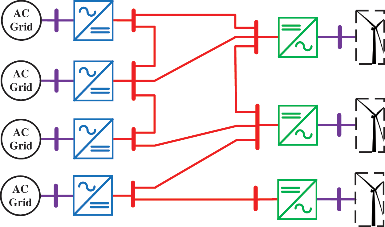
Figure 1: General configuration of Multiterminal HVDC system
The master VSC has the responsibility for voltage profile control while the remaining converters should control and regulate the active power [12]. The backbone of this control strategy is the requirement for a fast communication link which, in the case of communication link failure, is the main drawback of this method. Hence, this control strategy does not offer a high degree of reliability. Expanding the MTDC system based on master-slave control may require re-rating the master converter in order to guarantee safe system operation and stability conditions.
The voltage margin control (VMM) strategy was introduced to eliminate the need for a fast communication link. This strategy is similar to master-slave control. However, the responsibility for DC voltage control in the MTDC system is shared among all VSC terminals, based on local measurements such as DC voltage and active power. The dynamic response of this control strategy is the least effective compared to other methods because of its controller structure [13]. However, the VMM was modified with a P-V droop characteristic to improve the system dynamic response and performance.
Conventional voltage droop control strategy mainly depends on the local converter measurement, which is known as a decentralized control [8]. The use of the P-V droop characteristic method in the MTDC system does not require communication infrastructure, but it is challenging to achieve precise power sharing among MTDC terminals [9]. Furthermore, the extra available power that can be shared is restricted due to the pre-defined droop controller coefficient. The associated issue of the voltage droop control is the determination of the droop coefficient based on the converter rating, which imposes a difficult constraint on power sharing among MTDC converters.
Adaptive voltage droop control has been introduced in order to include the available power of the converter. This control strategy is capable of preventing the possibility of overloading condition [10]. However, the droop coefficient was preselected based on the converter rating once one of the converters is disconnected. In other words, the variable coefficient of DC voltage droop could be affected due to the DC power losses in MTDC lines. Nonetheless, this control strategy requires communication infrastructure [14].
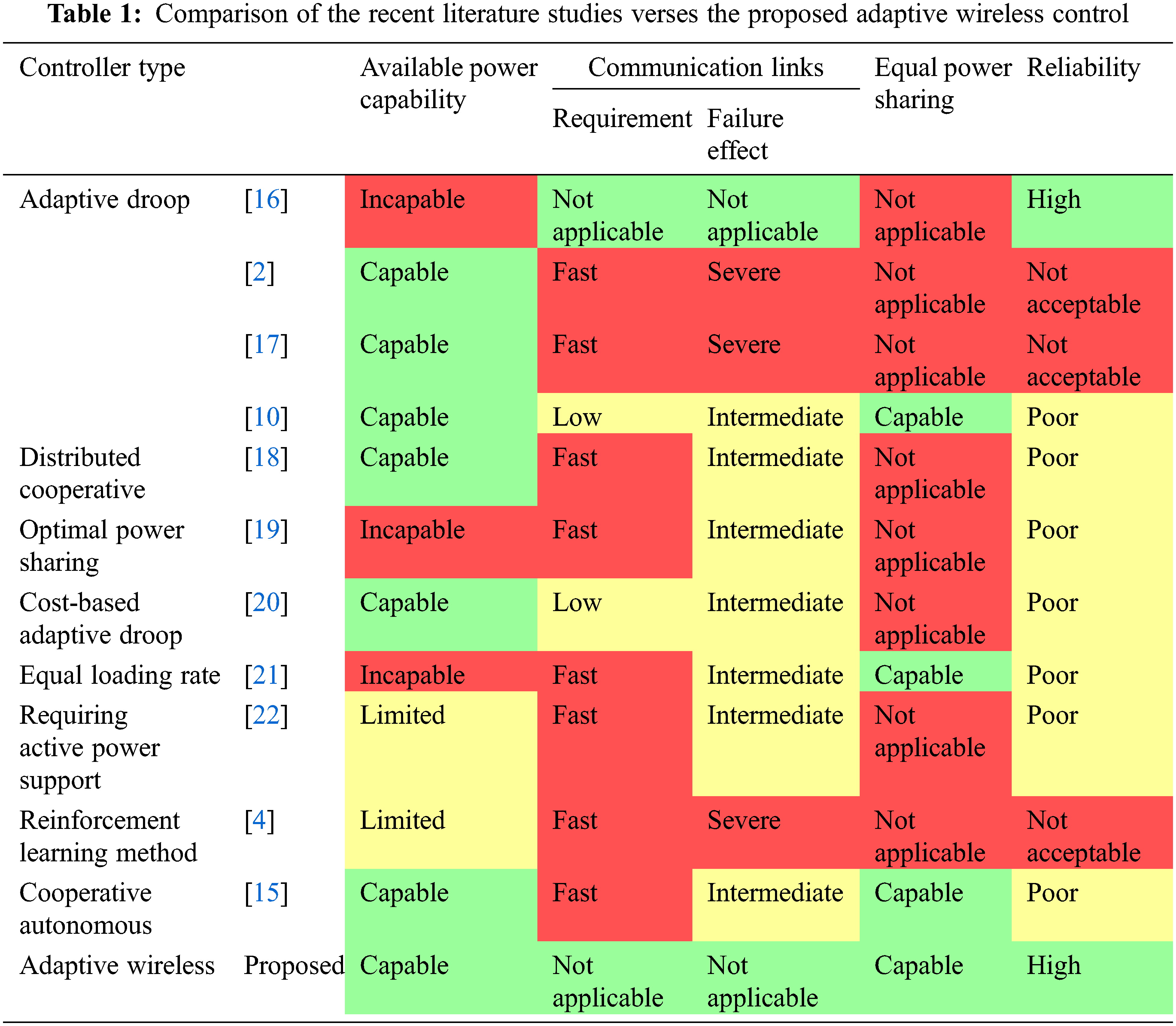
Power sharing control among multiterminal HVDC systems in the literature is based on conventional droop control, priority sharing, ratio-based sharing, voltage margin control, or adaptive droop control. Therefore, the lack of available power inclusion as a control variable is an issue in MTDC system power sharing. The rationale for this issue is the use of a fixed and predefined power sharing coefficient [2,5,15]. The aforementioned techniques do not offer precise or equal power sharing among multiterminal HVDC systems. Hence, there are several control techniques have been introduced recently in the literature based on communication links between the MTDC converter stations. Each of the recent proposed controller has some advantages and disadvantages. A comprehensive comparison of the recent literature proposals is summarized in Tab. 1. The comparison is evaluated based on some desire features need to be achieved such as the capability of sharing available power, avoiding the need of communication links between the converter station, and providing the equal power sharing in case of power shortage. Nevertheless, using power sharing control based on a communication link decreases the system reliability in the case of lost communication.
The main contribution of this paper is the introduction of a new decentralized adaptive wireless control for power sharing among multiterminal HVDC converters to ensure equal power sharing between converter stations and sharing available power in rectifier stations. The proposed new control is examined using a simulation tool that is named the PSCAD/EMTDC environment.
This paper is organized into five sections: Section 2 provides a brief overview of the MTDC system model used for the study. Section 3 explains the cascaded converter controller method. Section 4 presents the proposed adaptive wireless controller and its implementation, while Section 5 discusses simulation results and performance. The final section presents the conclusions from this work.
The considered layout of the MTDC system is demonstrated by Fig. 2. This configuration of an MTDC system, which was retrieved from [23], is based on a practical system that consists of four converter terminals and DC transmission lines. A fixed DC voltage level or a small window of DC voltage variation is necessary to stabilize the MTDC system. Each of the converter terminals must have the capability to control different electrical quantities such as active power, reactive power, AC voltage, and AC system frequency.
The choice of the controller target depends on the AC grid side of the converter terminal. When the converter is connected into passive AC, the converter must control the system frequency and AC voltage at the point of common coupling (PCC). Once the converter is connected into a stiff AC system, then the role of the controller is to control the active and reactive power or DC voltage due to the maintained AC voltage and frequency at the PCC. Nevertheless, when the converter is connected to a weak AC system, then the target of the converter controller can control the AC voltage with either the DC voltage or active power depending on the operation requirements. Therefore, it becomes necessary that one of the converter terminals must be responsible for regulating the DC voltage, while the rest of the converters are based on active power control where an AC passive system is absent.
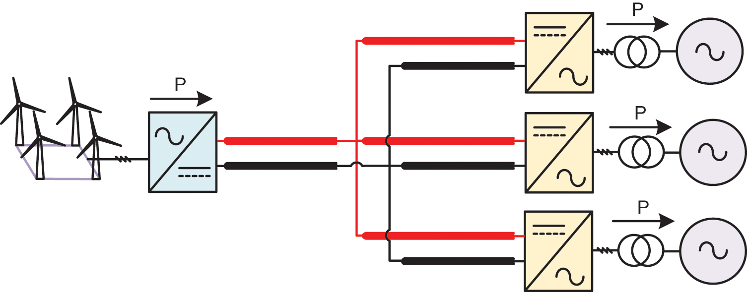
Figure 2: System under study
According to the literature, several control methods can be applied to control the electrical quantities of a converter terminal. These methods are: direct power control based on a natural reference frame (abc); proportional resonance control based on a stationary frame (αβ); and vector control based on a synchronous reference frame (d-q). Each of the control methods has some advantages and disadvantages. However, achieving decoupled independent control for active and reactive power is the main merit of using a synchronous reference frame (SRF) control concept. This control method is commonly used due to low voltage harmonics production [24,25], which is used in this work. Since the controller method of each converter in the MTDC system is based on a vector d-q synchronous reference frame (SRF), it becomes necessary to drive the dynamic converter. The generalized primary controller loop of a converter station is formed via a cascaded inner current controller and outer voltage controller loops.
3.1 Converter Inner Controller
Developing and designing the converter inner controller loop can be achieved using AC filter differential equations. The voltage drop at the AC side of the converter filter can be calculated by applying Kirchhoff's voltage law. According to the schematic single line of a converter terminal as presented in Fig. 3, the dynamic differential equations of the AC filter model based on an SRF are given by (1) and (2).
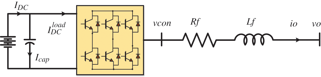
Figure 3: General schematic of a converter terminal
The nonlinear derivative terms in (1) and (2) can be evaluated using the proportional integral (PI) controller to track the instantaneous filter current
The block diagram of the current controller loop can be developed by substituting (3) and (4) into (1) and (2), as presented in Fig. 4. The feed-forward gain (H) is normally equal to one for an MTDC system application, but a gain of less than one leads to an expansion in the current controller bandwidth [26].
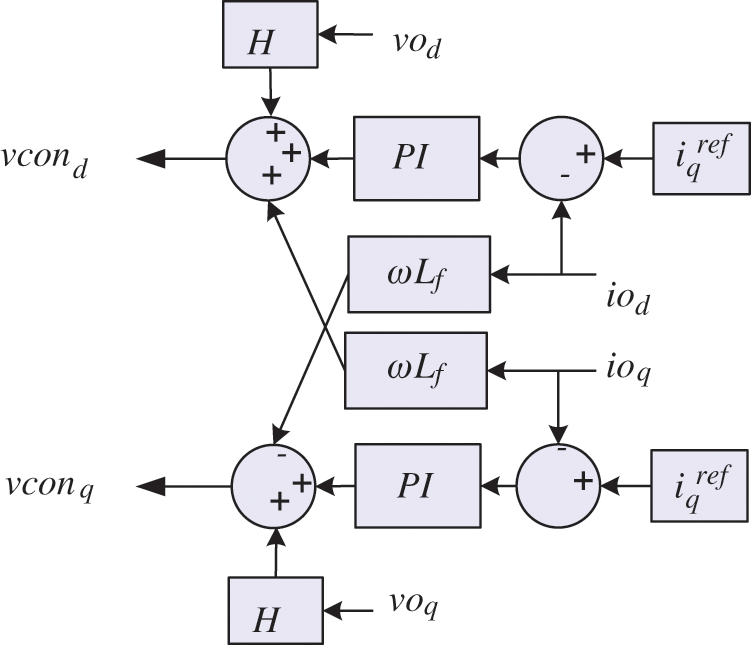
Figure 4: Block diagram of the inner current controller
3.2 Converter Outer Controller
The current references are generated from the outer controller loop based on a predefined target [2]. Due to the independent decouple control feature of the vector control method, the d-axis vector is correlated to control the active power and the DC voltage control while controlling the reactive power and AC voltage at the PCC is associated with the q-axis.
According to the power balance equation based on Fig. 3, the summation of the input DC and output AC power is equal to zero under an assumption that the converter is lossless, as shown in (5).
where the power terms in (5) are expanded as follows:
Manipulating (5) after substituting (6) and (7) results in achieving the DC voltage controller equation, as illustrated in (8). The outer controller to regulate the DC voltage based on (9), after replacing the nonlinear derivative term with the PI transfer function, is depicted in Fig. 5. However, the negative feed-forward can be eliminated by proper tuning of the PI controller gains.
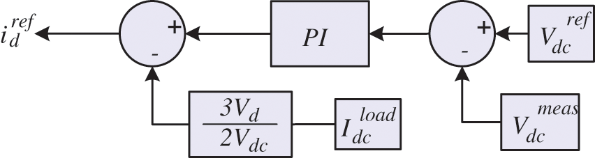
Figure 5: Block diagram of the DC voltage controller
The active and reactive power can be controlled directly according to (7). Hence, dividing the power desired reference by
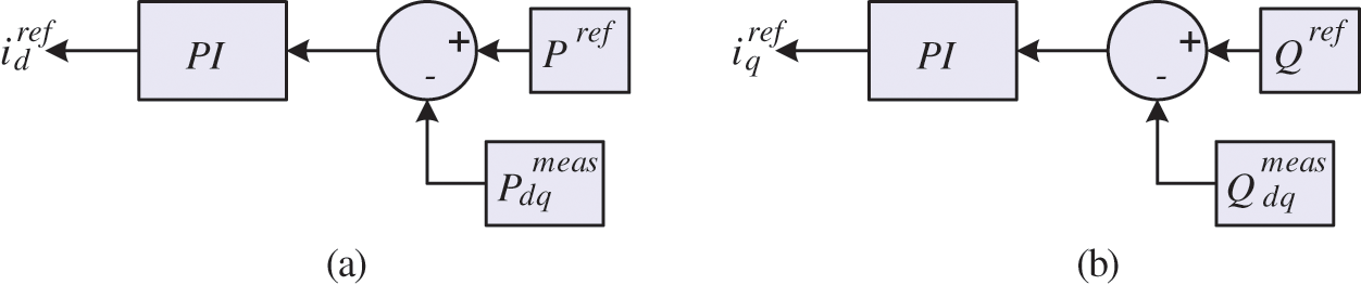
Figure 6: Block diagram of the outer voltage controller. (a) Active power controller (b) Reactive power controller
3.3 Converter Cascaded Controller
The entire controller loop structure, including Park transformation and phase locked loop of a voltage source converter (VSC) is displayed in Figs. 7, and 8, respectively. The power controller structure, based on a cascaded vector SRF, is illustrated in Fig. 7, while Fig. 8 presents the converter controller structure for DC voltage regulation. In fact, the proposed adaptive wireless control is applied to the outer controller power reference of the converter station.
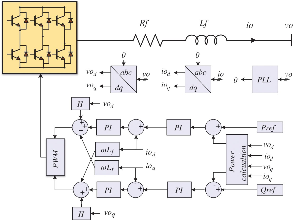
Figure 7: Controller loop of each VSC-based P-Q control
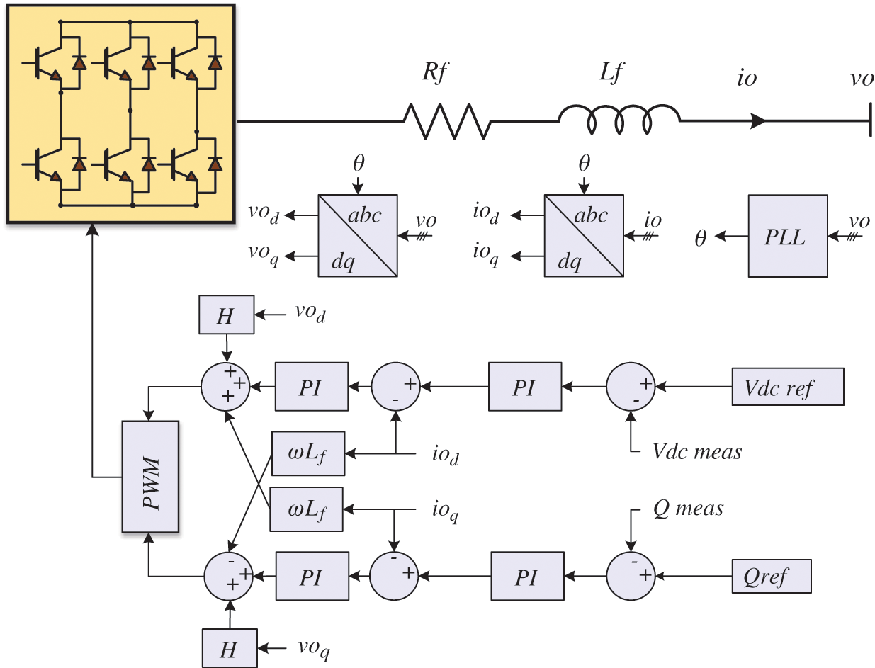
Figure 8: Controller loop of each VSC-based Vdc-Q control
4 Proposed Adaptive Wireless Controller
Referring to Fig. 2, each converter controller loop can request the desire active power from the MTDC based on its AC system operation conditions or independent system operator (ISO). From an electricity deregulation perspective, there should be rules and policies set among converter stations by a regulator which, in this paper, is assumed to be equal power sharing. Therefore, it is allowable for all converter stations to request power above the agreement if there is available power at the rectifier station. However, in the case of all converter requests above the agreement, the proposed controller based on only local measurements will share the power according to the agreement policies.
The agreement between all stations will prevent any possibility of an overloading condition at the rectifier station. The main objective of the converter station being based on local measurements is to collect the desired power from the MTDC system in the case there is available power. Otherwise, the converter station will obtain the power based on the agreement value since the rectifier terminal is assigned to control the MTDC system DC voltage using the traditional droop control. Fig. 9 presents the applied P-Vdc droop characteristic in the rectifier terminal.
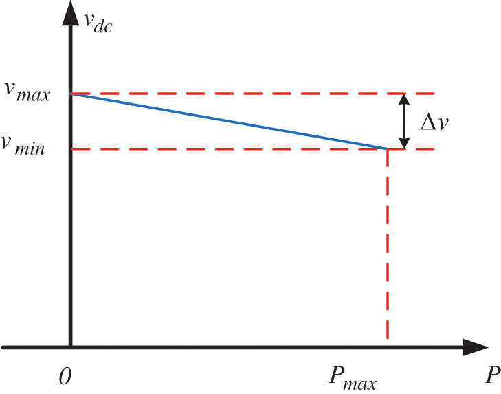
Figure 9: Droop characteristic
The mathematical representation of the droop characteristic based on Fig. 9 is shown in (9). Where
Since the DC voltage of the entire MTDC varies according to the loading conditions, local measuring of the DC voltage at each terminal indicates the available power that can be consumed or requested by a terminal that works in inversion operation mode. It is clear that the rectifier terminal is operated as a slack bus in a conventional AC power system application. Therefore, the other converters working in inversion mode can calculate the available power at the rectifier station from their local measurements using (10).
The superscript
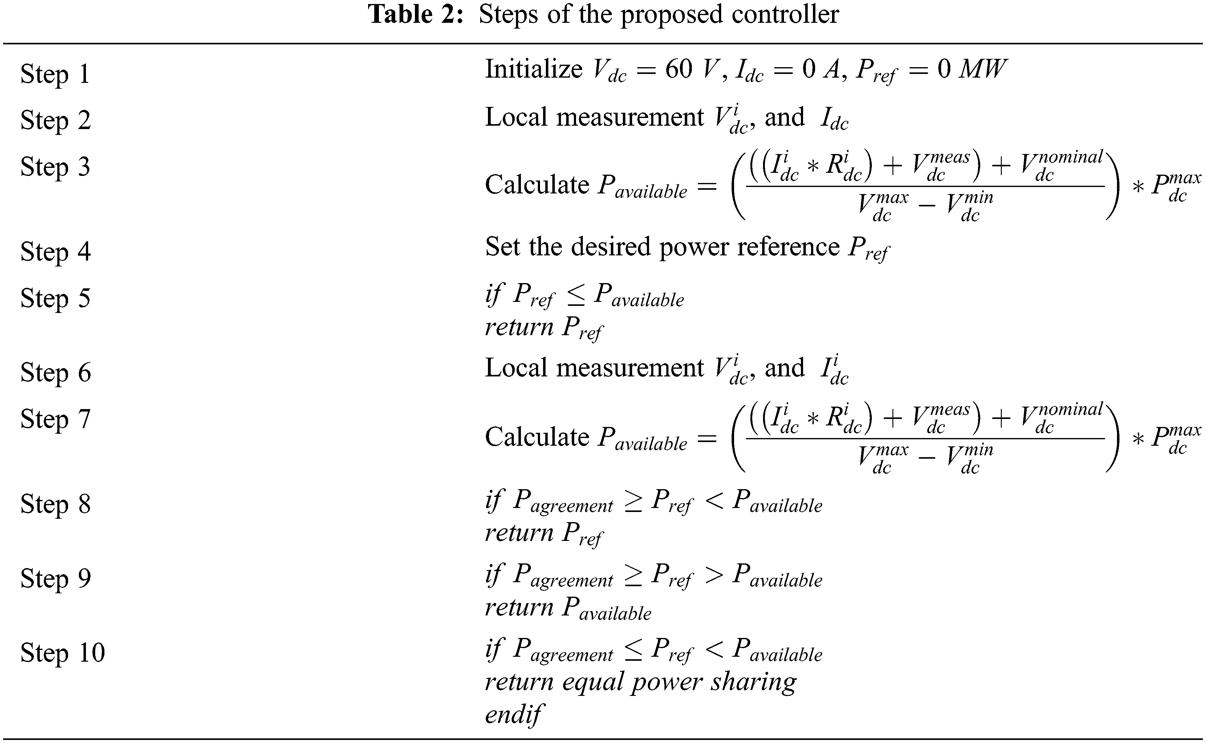
The formal mathematical formulation of the proposed decentralized adaptive wireless controller has been previously discussed in (9) and (10) respectively. However, the development of the proposed controller based on algorithm pseudocode is shown in Tab. 2. The algorithm continuously calculates and compares the required power with both the available and maximum power that can be collected.
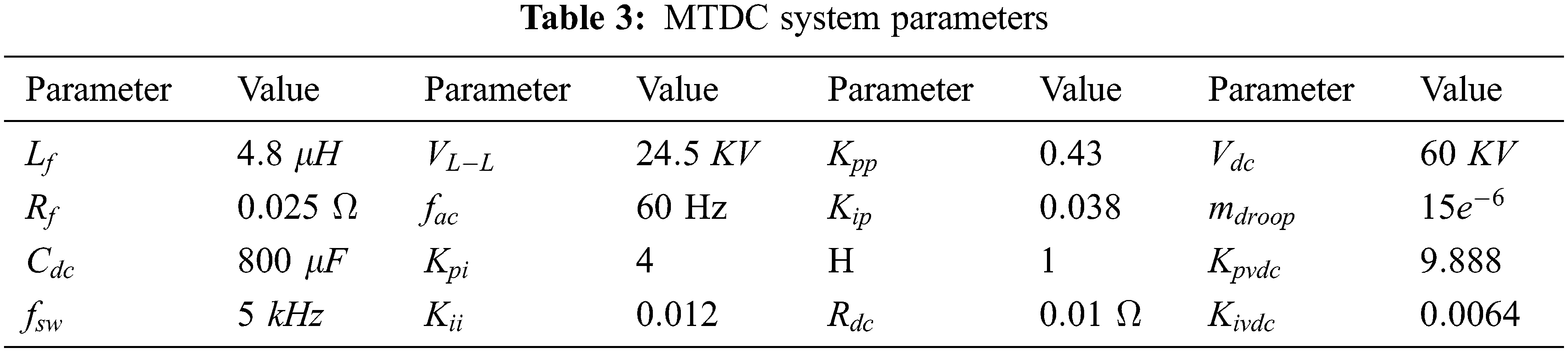
The system parameters are presented in Tab. 3. The study was conducted to examine the flexibility and adaptability of the proposed controller within different scenarios. The MTDC system shown in Fig. 2 has been developed and simulated in a PSCAD/EMTDC environment.
Tab. 4 lists the power references that were applied to reveal the advantages of the proposed controller. Indeed, all the test scenarios in this paper are focused on the active power flow in the MTDC system.
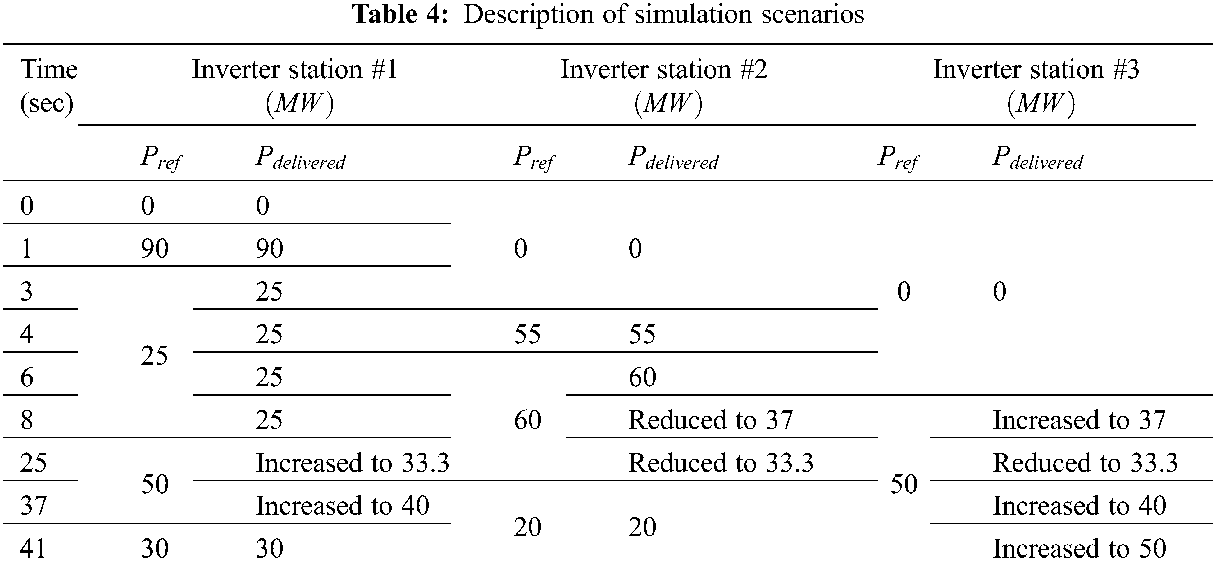
Initially, at t = 0 s, the power flow in the MTDC system is equal to zero due to the fact that, as shown in Fig. 10, not all inverter request power and MTDC system DC voltage is equal to 60 kV, as depicted in Fig. 11. At t = 1 s, Inverter #2 requests 90 MW, which is available at the rectifier station. Therefore, Inverter #2 will achieve this order as far as there is no request from other inverters. At the same time, the DC voltage reduces to 58.5 kV according to droop controller characteristics.
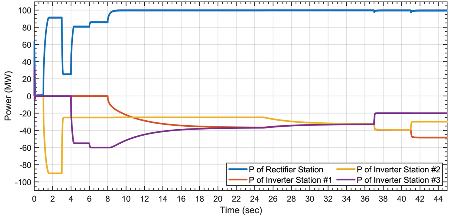
Figure 10: Power sharing between converter stations
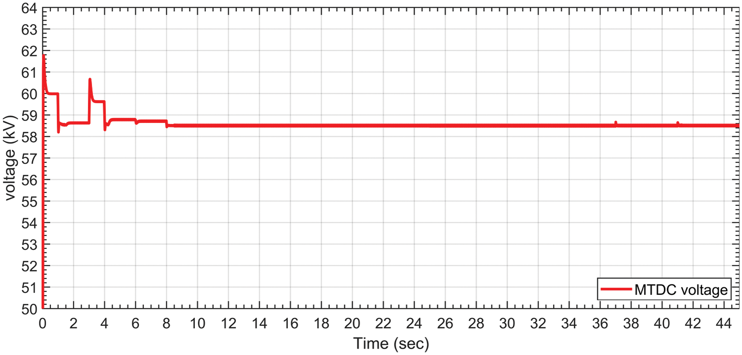
Figure 11: DC voltage of the MTDC system at the rectifier terminal
At t = 3 sec, Inverter #2 reduces the required absorbed power to be equal to 25 MW. Therefore, the DC voltage increases accordingly which, in this situation, is approximately equal to 59.65 kV, as shown in Fig. 11.
At t = 5 s, Inverter #2 continues to consume 25 MW, and Inverter #3 requests 55 MW. Due to the availability of power that can be consumed at the rectifier station, both Inverters #2 and #3 will collect their requirements. In this case, the DC voltage decreases to almost 58.78 kV.
At t = 6 s, Inverter #3 further increases its order to be equal to 60 MW. At this time, the rectifier station still does not reach its rated limit and can supply both inverters. In this scenario, the total supplied power from the rectifier terminal is 85 MW, while the DC voltage of the MTDC is approximately equal to 58.7 kV, as shown in Fig. 11.
Since the power rating of the rectifier station is 100 MW, supplying 85 MW to Inverters #2 and #3 is valid. Inverter #1 starts to request 40 MW at t = 8 s. In this scenario, the DC voltage reaches the lowest value as shown in Fig. 11, and the power will be shared equally between Inverters #1 and #3, which is the merit of the proposed controller, as can be seen in Fig. 10. The rationale is that the rectifier station reaches its rated power limit and, at the same time, Inverter #2 still consumes less active power than the agreement value. In other words, once more than two inverter stations request power over the agreement value, the controller will then equally divide the remaining amount of available power between the inverter stations. It can be clearly observed from Fig. 10 that the consumed power via Inverters #1 and #3 is identical.
At t = 25 s, Inverter #2 requests 50 MW, and both Inverters #1 and #3 consume 37 MW. As a result, the controller will reduce the consumed power by Inverters #1 and #3 to meet the agreement value for all inverter stations. The shortage of required power at inverter stations can be compensated from their dispatchable units at the AC side.
At t = 37 s, Inverter #3 reduces the requested power from 60 to 20 MW. Consequently, the collected power via Inverters #1 and #2 will increase according to the requested power reduction from Inverter #3 due to the power availability at the rectifier station. In other words, when any inverter does not request its full power percentage, the other inverters can benefit from the available power.
Finally, at t = 41 s, Inverter #2 decreases the required power from 50 to 30 MW, while Inverter #1 still requires 60 MW. In this situation, Inverter #1 will collect the available power which, in this case, is more than the agreement value and is equal to 50 MW.
The efficient operation of an MTDC system mainly depends on the DC voltage and power sharing control. Therefore, the communication-based controller has less reliability in the case of communication failure. Thus, this paper proposes a new adaptive wireless control for power sharing among converter stations in MTDC systems. The results show that the proposed control is robust in the case of uncertain power requests by inverter stations. The proposed control strategy is reliable in preventing the possibility of overload conditions due to the fact that it does not need communication infrastructure. Nevertheless, through case scenarios, it is observed that several important benefits of the proposed controller are shown, such as the capability for equal power sharing, the prevention of overloading condition, the consideration of available power sharing, a reduction in operation cost in the AC system and, finally, the increased utilization of all converter stations.
Funding Statement: The author received no specific funding for this study.
Conflicts of Interest: The author declares that they have no conflicts of interest to report regarding the present study.
References
1. H. Alsiraji, “Cooperative power sharing control in multi-terminal VSC-HVDC,” M.S. thesis, University of Waterloo, Canada, 2014. [Google Scholar]
2. M. A. Abdelwahed and E. F. El-saadany, “Power sharing control strategy of multiterminal VSC-HVDC transmission systems utilizing adaptive voltage droop,” IEEE Transactions on Sustainable Energy, vol. 8, no. 2, pp. 605–615, 2017. [Google Scholar]
3. J. Li, Y. Li, L. Xiong, K. Jia and G. Song, “DC fault analysis and transient average current based fault detection for radial MTDC system,” IEEE Transactions on Power Delivery, vol. 35, no. 3, pp. 1310–1320, 2018. [Google Scholar]
4. Z. J. Hu, Z. W. Liu, C. Li, T. Huang and X. Hu, “A model-free distributed cooperative frequency control strategy for MT-HVDC systems using reinforcement learning method,” Journal of the Franklin Institute, vol. 358, no. 13, pp. 6490–6507, 2021. [Google Scholar]
5. K. Alshammari, H. A. Alsiraji and R. El Shatshat, “Optimal power flow in multi-terminal HVDC systems,” in Proc. EPEC, Toronto, ON, Canada, pp. 1–6, 2018. [Google Scholar]
6. K. Alshammari, H. Alrajhi and R. El-Shatshat, “Optimal power flow for hybrid AC/MTDC systems,” Arabian Journal for Science and Engineering, vol. 9, no. 1, pp. 4112, 2021. [Google Scholar]
7. J. Beerten, S. Cole and R. Belmans, “Modeling of multi-terminal VSC HVDC systems with distributed DC voltage control,” IEEE Transactions on Power Systems, vol. 29, no. 1, pp. 34–42, 2014. [Google Scholar]
8. W. Wang and M. Barnes, “Power flow algorithms for multi-terminal VSC-HVDC with droop control,” IEEE Transactions on Power Systems, vol. 29, no. 4, pp. 1721–1730, 2014. [Google Scholar]
9. T. M. Haileselassie and K. Uhlen, “Impact of DC line voltage drops on power flow of MTDC using droop control,” IEEE Transactions on Power Systems, vol. 27, no. 3, pp. 1441–1449, 2012. [Google Scholar]
10. N. Chaudhuri and C. Balarko, “Adaptive droop control for effective power sharing in multi-terminal DC (MTDC) grids,” IEEE Transactions on Power Systems, vol. 28, no. 1, pp. 21–29, 2013. [Google Scholar]
11. S. Augustine, M. K. Mishra and N. Lakshminarasamma, “Adaptive droop control strategy for load sharing and circulating current minimization in low-voltage standalone DC microgrid,” IEEE Transactions on Sustainable Energy, vol. 6, no. 1, pp. 132–141, 2015. [Google Scholar]
12. D. Jovcic, “Interconnecting offshore wind farms using multiterminal VSC-based HVDC,” in Proc. IEEE Power Engineering Society General Meeting, Montreal, QC, Canada, pp. 1–7, 2006. [Google Scholar]
13. R. T. Pinto, P. Bauer, S. F. Rodrigues, E. J. Wiggelinkhuizen, J. Pierik et al., “A novel distributed direct-voltage control strategy for grid integration of offshore wind energy systems through MTDC network,” IEEE Journal of Emerging and Selected Topics in Power Electronics, vol. 60, no. 6, pp. 2429–2441, 2013. [Google Scholar]
14. A. Kirakosyan, E. F. El-Saadany, M. S. El Moursi and K. Al Hosani, “DC voltage regulation and frequency support in pilot voltage droop-controlled multiterminal HVDC systems,” IEEE Transactions on Power Delivery, vol. 33, no. 3, pp. 1153–1164, 2018. [Google Scholar]
15. H. K. A. Alsiraji and E. F. El Saadany, “Cooperative autonomous control for active power sharing in multi-terminal VSC-HVDC,” International Journal of Process Systems Engineering, vol. 2, no. 4, pp. 303–319, 2015. [Google Scholar]
16. W. Wang, Y. Li, Y. Cao, U. Hager and C. Rehtanz, “Adaptive droop control of VSC-MTDC system for frequency support and power sharing,” IEEE Transactions on Power Systems, vol. 33, no. 2, pp. 1264–1274, 2018. [Google Scholar]
17. A. Kirakosyan, E. F. El-Saadany, M. S. El Moursi, S. Acharya and K. Al Hosani, “Control approach for the multi-terminal HVDC system for the accurate power sharing,” IEEE Transactions on Power Systems, vol. 33, no. 4, pp. 4323–4334, 2018. [Google Scholar]
18. W. Wang, X. Yin, Y. Cao, L. Jiang and Y. Li, “A distributed cooperative control based on consensus protocol for VSC-MTDC systems,” IEEE Transactions on Power Systems, vol. 36, no. 4, pp. 2877–2890, 2021. [Google Scholar]
19. K. Alshammari, “Optimal power-sharing control for MTDC systems,” M.S. thesis, University of Waterloo, Canada, 2020. [Google Scholar]
20. S. Song, R. A. McCann and G. Jang, “Cost-based adaptive droop control strategy for VSC-MTDC system,” IEEE Transactions on Power Systems, vol. 36, no. 1, pp. 659–669, 2021. [Google Scholar]
21. Y. Wang, J. He, Y. Zhao, G. Liu, J. Sun et al., “Equal loading rate based master-slave voltage control for VSC based DC distribution systems,” IEEE Transactions on Power Delivery, vol. 35, no. 5, pp. 2252–2259, 2020. [Google Scholar]
22. Z. Li, Z. Wei, R. Zhan, Y. Li and Y. Tang, “Frequency support control method for interconnected power systems using VSC-MTDC,” IEEE Transactions on Power Systems, vol. 36, no. 3, pp. 2304–2313, 2021. [Google Scholar]
23. K. Rudion, A. Orths, P. B. Eriksen and Z. A. Styczynski, “Toward a benchmark test system for the offshore grid in the North Sea,” in Proc. IEEE Power Engineering Society General Meeting, Minneapolis, MN, USA, pp. 1–8, 2010. [Google Scholar]
24. H. Alrajhi Alsiraji and J. M. Guerrero, “A new hybrid virtual synchronous machine control structure combined with voltage source converters in islanded ac microgrids,” Electric Power Systems Research, vol. 193, pp. 1–11, 2021. [Google Scholar]
25. H. Alrajhi Alsiraji, “A new virtual synchronous machine control structure for voltage source converter in high voltage direct current applications,” Journal of Umm Al-Qura University for Engineering and Architecture, vol. 11, pp. 1–5, 2020. [Google Scholar]
26. H. Alsiraji, “Operational control and analysis of a hybrid AC/DC microgrid,” Ph.D. dissertation, University of Waterloo, Canada, 2018. [Google Scholar]
Cite This Article
 Copyright © 2023 The Author(s). Published by Tech Science Press.
This work is licensed under a Creative Commons Attribution 4.0 International License , which permits unrestricted use, distribution, and reproduction in any medium, provided the original work is properly cited.
 Downloads
 Citation Tools