DOI:10.32604/csse.2023.025738
| Computer Systems Science & Engineering DOI:10.32604/csse.2023.025738 | |
| Article |
Single Band EBG Antenna for Wireless Power Transfer Applications
1Department of Electrical Engineering, College of Engineering, Qassim University, Buraydah, 51452, Saudi Arabia
2Microwave Electronics Research Laboratory, El Manar University, Tunis, 2092, Tunisia
*Corresponding Author: El Amjed Hajlaoui. Email: hajlamjed@yahoo.fr
Received: 03 December 2021; Accepted: 21 February 2022
Abstract: This work demonstrates the design of a single band Electromagnetic Band Gap (EBG) antenna by employing an open stub EBG microstrip of a patch antenna for better achievements in terms of its performance to be utilized in a reconfigurable harvester to operate over a wide input power range. The EBG antenna has been used to gather RF energy and a FET-transistor has been obtainable to determine and control the power flow with the intention to operate at the same time for a different level of input power. The measured data of the EBG antenna shows a directivity of 8.52 dBi, a gain of 7.18 dBi, a return loss of −27 dB with a radiation efficiency of 84.3%, showing a clear enhancement in directivity, peak realized gain, and radiation efficiency by 41.76%, 25.61%, and 17.12% respectively compared with a regular reference antenna; without utilized the EBG structure. Moreover, the harvester design accomplishes 40% of RF-DC power conversion efficiency over a wide dynamic input power range from −15 to 27 dBm, and its peak is around 78%. The harvester is designed to work at the ISM band for 915 MHz and is suitable for Wireless Power Transfer (WPT) uses.
Keywords: EBG; rectifier; antenna; schottky diode; wireless power sensor; harvester
Nowadays, Wireless Power Transfer (WPT) is considered an important subject for researchers and innovators due to the high demand for portable devices with flexibility, sustainability, and reliability to the power source. In addition, diversities of applications for Wireless Sensor Network (WSN) devices need to be operated separately, such as Internet of Things (IoT), Internet of Everything (EoT), Artificial intelligent systems, and smart cities have been increased the need to have such a system [1,2]. In fact, WPT has two main categorizations, including the coupling resonators for both coupling/inductive and Radio Frequency (RF) approaches. The former is used for a short distance while the latter is utilized for a long distance [3]. In line with the advantages of long-range operation techniques and the need to have devices that suit miniaturized portable devices, this work has utilized the RF technique to harvest energy from ambient energy sources. Accordingly, a RF harvester, a critical part of WPT, has been explored to achieve a WPT system.
The proposed RF harvester block has a receiving RF antenna, matching network, rectifier circuitry, and output load, as displayed in Fig. 1. The main principle of the RF harvester is to transform the received ambient radio frequency signal available at the receiving antenna to the output voltage which likely a DC through a rectifier circuit with the aim to turn on portable devices or directly charge its battery [4]. The existing exploration directions are primarily concentrating on the harvester circuitry to develop and maximize conversion efficiency to power the WPT system.
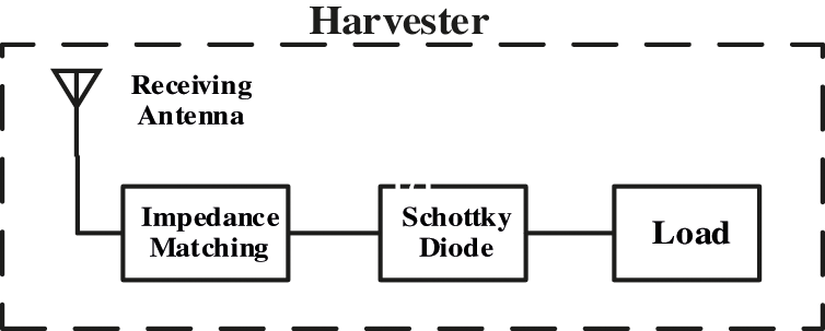
Figure 1: Harvester block diagram
Consequently, harvester ought to be designed to enhance its performance over a wide input power range to obtain higher Power Conversion Efficiency (PCE). Thus, more than a few antenna structures have been suggested for WPT [5–7]. Nevertheless, a tradeoff amongst antenna parameters is essential to ultimately unlock the ut-most power conversion efficiency in WPT systems, including power harvesting abilities, antenna size, and operation frequency. For example, a large antenna tends to lead to high gain and gains higher WPT system efficiency [8]. A compact antenna is indispensable for portable and miniaturized devices such as Radio-frequency Identification (RFID) and IoT devices to ease the integration with various applications [9]. Miniaturization of traditional antennas faces performance limitations in gain, bandwidth, and efficiency [10].
Therefore, a number of topologies and structures have been explored in the previous work such as in [11] diversity of ambient energy harvesting has been reviewed and its capability to operate as a stand-alone system for various of operation frequency at Industrial Scientific Medical (ISM) band mainly to power WSN. In addition, a tri-band slot antenna has been proposed for RF harvesting to operate at 2.45 GHz and achieves 5.53 dB of gain [12], while in [13] the authors proposed a design for a rectenna with wide-beam by using a multi-port metasurfaces-based antenna to enhance the energy system in [4], a rectenna with a tunable architecture was introduced to resolve the early breakdown voltage; however, it comes at the expense of the design size and complexity. Correspondingly, a Pseudomorphic High-Electron-Mobility-Transistor (pHEMT) connected in series with the proposed configuration of a diode was obtainable in [14]. This configuration was used in [15] to increase the performance of the rectifier by adding a resistance compression network (RCN). Furthermore, a multiport rectenna has been proposed in [16] to increase the PCE of the rectenna system. To increase the PCE of a harvester, a rectenna with adaptive reconfigurable was projected in an earlier work [17] to work at 900 MHz for the ISM frequency bands application.
Hence, in this work, the integration of EBG structure with a microstrip antenna is proposed to enhance its performance and improve the utilization in the antenna design due to their distinctive electromagnetic properties and capabilities including low cost, low profile, and easy integration which positively impact the antenna performance parameters: gain, directivity, resonance frequencies, coverage bandwidth and return loss [18–20]. It operates at 915 MHz, appropriate for light, compact and low cost MMID and RFID which operate within ISM radio frequency bands.
2 RF Energy Harvester Antenna Design
In this section, we deal with the design of an open stub EBG microstrip antenna for maximizing the RF signal harvested. Therefore, EBG structures were first introduced to overcome some antenna challenges in wireless communications, taking advantage of the properties of electromagnetic materials (EM). The EBG structure consists basically of periodic structure arrangements of a high and low dielectric substrate and metallic conductors. The mushroom-like EBG structures produce a band gap depending on the structure's periodicity illustrated in Fig. 2. It displays High Impedances Surfaces (HIS) and suppresses the propagation wave of its surfaces at a specific frequency band which is referred to as a band gap, accordingly reflect back coming waves without changing in the phase leading to improving and optimizing the antenna's characteristics [21,22]. The antenna gain can be enhanced by expanding the EBG structure in two diverse methods; the first structure can be applied as a superstrate and the other can be performed as a ground plane. In Multiple Input Multiple Output (MIMO) systems, using EBG structure increases the diversity gain and the isolation [23,24].
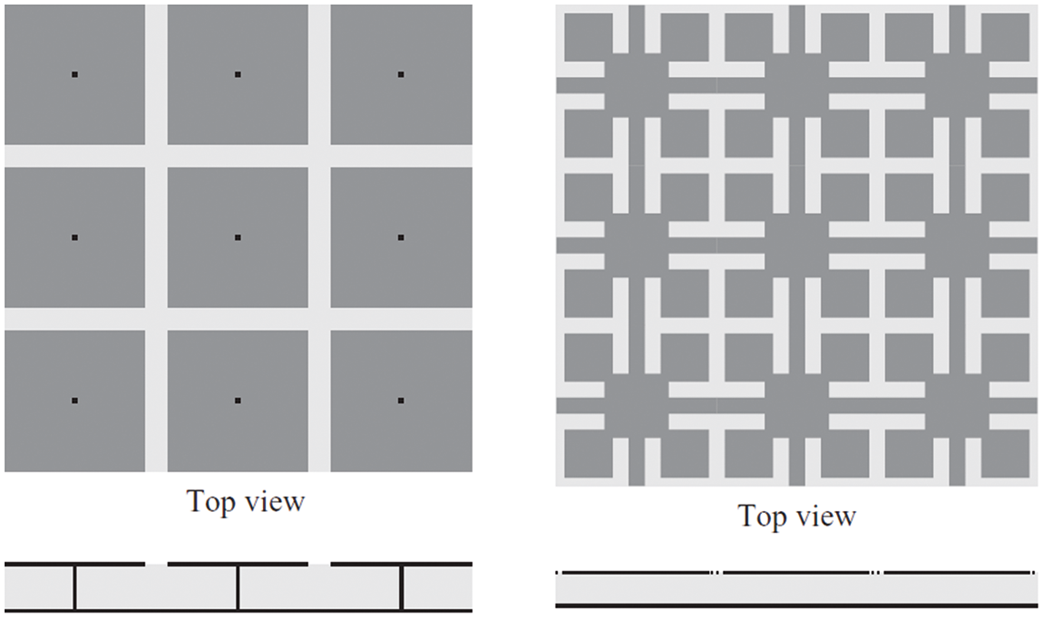
Figure 2: Illustrating 2-D of EBG surfacess: (Left) a mushroom-like surface and (Right) a uni-planar surface [24]
Different structure of antenna configurations including dipole, patch, Planar Inverted-F Antenna (PIFA), monopole, spiral, small antenna and parabolic antennas have been used to transmit and receive power energy in WPT systems for different locations. Nevertheless, to apply such antennas WPT system, the most critical characteristic in the receiver antenna is the aptitude to maximize the collection of the incident power at the receiving stage. Hence, integrating microstrip antennas with EBG structures can expand and improve the PCE of WPT systems.
For that reason, in this paper, a single band EBG antenna was employed as an open stub EBG microstrip of a patch antenna, as illustrated in Fig. 3. In fact, two techniques can be used to apply the EBG structure to the antenna proposed. The first technique employs a two-layer structure; the first layer contains an EBG layer while the antenna is located in the second layer. The EBG array near the feed line is the second approach, which is simple, straightforward, and cost-effective to implement. The amount of coupling changes with the distance variation amongst the feed line and the structure of EBG antenna. Therefore, such a crucial parameter can be modified to achieve high performance and the resonate frequency of the band gap can be changing a little with the predicted one.
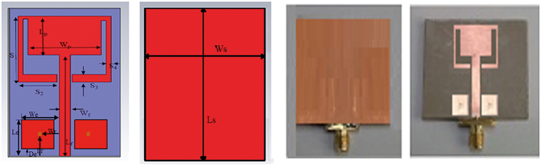
Figure 3: Geometrical configuration and fabricated prototype of the open stub EBG microstrip antenna
Therefore, the EBG structure is initially combined using a microstrip antenna. Its structure performance depends on its physical dimension parameters, namely the EBG patch width (We), the gap between the patches (g), via radius (r), the thickness (h), and permittivity substrate (εr). The patch width determines the resonant frequency, whereas the gap variation determines the frequency band of the EBG surface. By adjusting the substrate thickness, reduction in the frequency and increase in the bandwidth can be achieved. Substrate permittivity controls the frequency behavior [24].
Consequently, the EBG patch antenna design was illustrated in Fig. 3 and is implemented as an open stub rectangular patch antenna. An antenna implementation on FR4 substrate material with a 48 mm × 30 mm size has been proposed. On one side, the substrate has a relative dielectric constant of εr = 4.3 and loss tangent, tan δ = 0.025, and thickness of h = 1.6 mm to support 915 MHz operation frequency. Tab. 1 shows the geometrical dimensions of the EBG antenna. The feed line length is chosen to be 32.9 mm to maximize the transfer power at the characteristic impedance of 50 ohms. The 50 Ohm microstrip feed line and the radiation of the patch antenna are engraved on the same surfaces of the substrate. On the opposite surface, the rectangular ground is carved. Multi-resonant-length antennas are constructed by incorporating rectangular split-ring slots enclosed inside rectangular patches to operate in the 915 MHz band.

To evaluate the harvester, the most critical factor in WPT is the amount of power that can be transmitted and received via a signal. The attenuation of radio energy amongst the transmitter and receiver RF antennas in the Free Space Path Loss (FSPL) is given by Friis free space equation, where the amount of the received power can be calculated as:
λ is refer to the signal wavelength while Pt and Pr are the transmitted and received power, while Gt and Gr represent the antennas’ gains at both transmitter and receiver. The distance between two antennas, transmitter and receiver is represented by R. The smaller antenna size and lower attenuation make the 900 MHz band a suitable frequency for wireless power transmission. Taking into account the Federal Communications Commission's regulations regarding the allowed output power transmitted which is around 30 dBm while the maximum Effective Isotropic Radiated Power (EIRP) is about 36 dBm [25], researchers investigate a tradeoff among antenna dimension, free-space path loss, and amount of power received. Therefore, harvester performance can be characterized and evaluated by various design parameters such as : overall power conversion efficiency (PCE), sensitivity, and output load [26].
3 Experimental Results and Discussion
The proposed EBG antenna was simulated by using a commercial simulator, Computer Simulation Technology (CST), and it's implemented on FR4 substrate material with dielectric constant of εr = 4.3 and loss tangent, tan δ = 0.025, and thickness of h = 1.6 mm to operate at 915 MHz. It consumes area of 48 mm × 30 mm. The proposed antenna measured at the anechoic chamber and its results exhibit 8.92 dBi of antenna directivity, 7.38 dBi of antenna gain and radiation efficiency of 0.843 with a reflection coefficient at 915 MHz greater than 25 dB as shown in Figs. 4 and 5 respectively. Fig. 4 presents the 3-dimensions of the radiation pattern for the open stub EBG antenna, which illustrates the gain and directivity. Both the simulated and measured far-field radiation patterns of the proposed antenna is presented as well as its normalized radiation patterns at the given resonant frequencies. The patterns are almost directional in the planes H plane (x-y plane) and E plane (x-z plane). Fig. 5 compares between the return loss of the reference open stub antenna and after embedding the EBG structures. The results for both simulated and measured return loss of the open stub EBG antenna show an agreement, achieving around −28 dB of return loss. Similarly, the measured data for the reference open stub antenna are consistent with the simulated one, having a return loss of 19 dB. The variance between simulations and measurements results from a misalignment in the anechoic chamber, which is not considered by software.
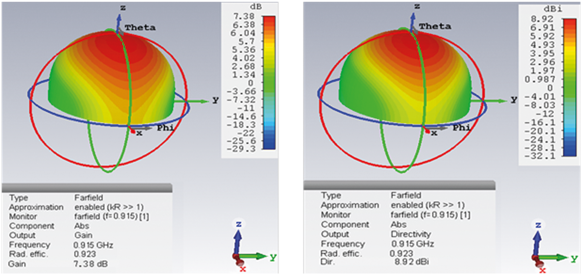
Figure 4: 3D radiation pattern of the open stub EBG antenna
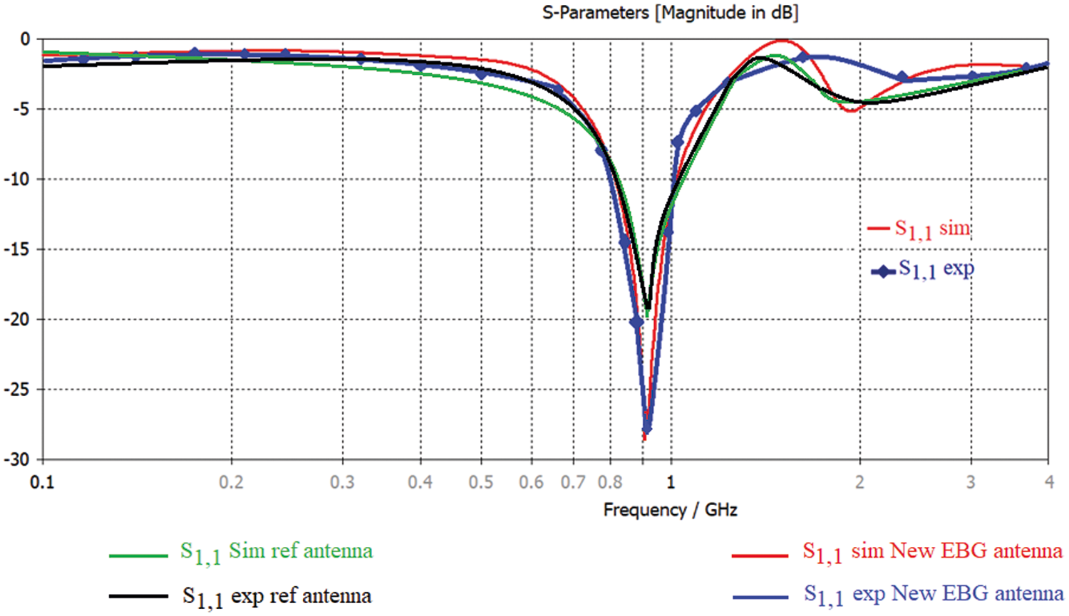
Figure 5: Reflection coefficient of the open stub antenna with EBG structures and without EBG (ref)
Tab. 2 summarizes the impact of incorporating EBG structures into the open stub microstrip antenna on the antenna performance parameters. It is apparent that by inserting the EBG structures, a clear enhancement is achieved in directivity, peak realized gain, and radiation efficiency by 41.76%, 25.61% and 17.12% respectively.

To evaluate the harvester (rectenna) performance, the proposed antenna is combined with the proposed adaptive rectifier in [27] through a 3-pin coupler, as illustrated in Fig. 6 using Keysight's Advanced Design System (ADS 2020) which is a commercial simulator. As stated in [28] “it is used as monotonic frequency depended power to excite the circuit.”

Figure 6: The schematic circuit of the proposed harvester
The proposed harvester achieves over than 40% efficiency across a wide input power range starting at −15 dBm and reach about 27 dBm, with the maximum peak efficiency (PCE) of 78% at 13 dBm of input power, as illustrated in Fig. 7a while Fig. 7b illustrates the PCE as a function of frequency which is operated at its maximum of PCE at 915 MHz for different input power. In addition, the return loss at the center frequency is around −20 dB, as displayed in Fig. 8. The designed harvester is implemented to work at high PCE and operate over an extensive range of input power levels. For the same rea-son, the load resistor is carefully chosen to be around 1 kΩ. In the rectified output circuit, a low-pass filter comprises the inductor (L5) and capacitor (C1) and to rectify the output. Via a SMA connector, the capacitor (C10) be located to match the designed rectifier circuit to the 50.

Figure 7: Power conversion efficiency of the proposed harvester: (a) vs. input power at output load of 1 kΩ. (b) vs. frequency and different input power

Figure 8: Return loss (S11) of the proposed harvester
In this paper, an adaptive harvester design using an open stub EBG antenna was presented to work for the ISM band for Wireless Power Transfer application at 915 MHz to accomplish a design operating over wide range of input power. Such design demonstrated an enhancement in the harvester's operation for wide-ranging of input power levels. The EBG antenna was validated and compared through a simulated result; resulting a clear enhancement in directivity, peak realized gain, and radiation efficiency by 41.76%, 25.61% and 17.12% respectively. With aim of having a harvester, the EBG antenna has been combined with an adaptive harvester and its achieved more than 40% of the power conversion efficiency (PCE) which is converted from RF-DC over a wide dynamic range of RF input power levels and it is starting from −15 dBm and ending by 27 dBm at a peak of PCE of 78% at 13 dBm.
Funding Statement: The authors gratefully acknowledge Qassim University, represented by the Deanship of Scientific Research, on the financial support for this research under the number (10262-qec-2020-1-3-I) during the academic year 1441 AH/2020 AD.
Conflicts of Interest: The authors declare that they have no conflicts of interest to report regarding the present study.
1. G. K. Ottman, H. F. Hofmann, A. C. Bhatt and G. A. Lesieutre, “Adaptive piezoelectric energy harvesting circuit for wireless remote power supply,” IEEE Transactions on Power Electronics, vol. 17, no. 5, pp. 669–676, 2002. [Google Scholar]
2. K. Niotaki, A. Georgiadis, A. Collado and J. S. Vardakas, “Dual-band resistance compression networks for improved rectifier performance,” IEEE Transactions on Microwave Theory and Techniques, vol. 62, no. 12, pp. 3512–3521, 2014. [Google Scholar]
3. C. Alippi and C. Galperti, “An adaptive system for optimal solar energy harvesting in wireless sensor network nodes,” IEEE Transactions on Circuits and Systems I: Regular Papers, vol. 55, no. 6, pp. 1742–1750, 2008. [Google Scholar]
4. Y. K. Tan and S. K. Panda, “Optimized wind energy harvesting system using resistance emulator and active rectifier for wireless sensor nodes,” IEEE Transactions on Power Electronics, vol. 26, no. 1, pp. 38–50, 2011. [Google Scholar]
5. V. Marian, V. B. Allard, C. Vollaire and J. Verdier, “Strategy for microwave energy harvesting from ambient field or a feeding source,” IEEE Transactions on Power Electronics, vol. 27, pp. 4481–4491, 2012. [Google Scholar]
6. K. Carver and J. Mink, “Microstrip antenna technology,” IEEE Transactions on Antennas and Propagation, vol. 29, no. 1, pp. 2–24, 1981. [Google Scholar]
7. P. Nintanavongsa, U. Muncuk, D. R. Lewis and K. R. Chowdhury, “Design optimization and implementation for RF energy harvesting circuits,” IEEE Journal on Emerging and Selected Topics in Circuits and Systems, vol. 2, pp. 24–33, 2012. [Google Scholar]
8. M. H. Ouda, W. Khalil and K. N. Salama, “Wide-range adaptive RF-to-DC power converter for UHF RFIDs,” IEEE Microwave and Wireless Components Letters, vol. 26, no. 8, pp. 634–636, 2016. [Google Scholar]
9. J. -K. Huang, W. -T. Hung, T. -H. Cheng and S. -Y. Chen, “A 2.45-GHz high-efficiency loop-shaped PIFA rectenna for portable devices and wireless sensors,” in Proc. of 2015 IEEE Int. Symp. on Antennas and Propagation & USNC/URSI National Radio Science Meeting, Vancouver, BC, Canada, pp. 1284–1285, 2015. [Google Scholar]
10. C. L. Holloway, E. F. Kuester, J. A. Gordon, J. O'Hara, J. Booth et al., “An overview of the theory and applications of metasurfaces: The two-dimensional equivalents of metamaterials,” IEEE Antennas and Propagation Magazine, vol. 54, no. 2, pp. 10–35, 2012. [Google Scholar]
11. T. Soyata, L. Copeland and W. Heinzelman, “RF energy harvesting for embedded systems: A survey of tradeoffs and methodology,” IEEE Circuits and Systems Magazine, vol. 16, pp. 22–57, 2016. [Google Scholar]
12. C. R. Valenta and G. D. Durgin, “Harvesting wireless power: Survey of energy-harvester conversion efficiency in far-field, wireless power transfer systems,” IEEE Microwave Magazine, vol. 15, no. 4, pp. 108–120, 2014. [Google Scholar]
13. V. Marian, B. Allard, C. Vollaire and J. Verdier, “Strategy for microwave energy harvesting from ambient field or a feeding source,” IEEE Transactions on Power Electronics, vol. 27, no. 11, pp. 4481–4491, 2012. [Google Scholar]
14. Z. Liu, Z. Zhong and Y. Guo, “Enhanced dual-band ambient RF energy harvesting with ultra-wide power range,” IEEE Microwave and Wireless Components Letters, vol. 25, no. 9, pp. 630–632, 2015. [Google Scholar]
15. Y. Zhou, B. Froppier and T. Razban, “Study of a matching circuit effect on a microwave rectifier,” in Proc. of Mediterranean Microwave Symp., Hammamet, Tunisia, pp. 29–33, 2011. [Google Scholar]
16. M. Han, S. Jung and H. Sohn, “High efficient rectenna using a harmonic rejection low pass filter for RF based wireless power transmission,” in Proc. of 11th Int. Symp. on Wireless Communications Systems, Barcelona, Spain, pp. 423–426, 2014. [Google Scholar]
17. H. Sun, Z. Zhong and Y. X. Guo, “An adaptive reconfigurable rectifier for wireless power transmission,” IEEE Microwave and Wireless Components Letters, vol. 23, no. 9, pp. 492–494, 2013. [Google Scholar]
18. F. Yang and Y. Rahmat-Samii, “Microstrip antennas integrated with electromagnetic band-gap (EBG) structures: A low mutual coupling design for array applications,” IEEE Transactions on Antennas and Propagation, vol. 51, no. 10, pp. 2936–2946, 2003. [Google Scholar]
19. J. C. Iriarte, I. Ederra, R. Gonzalo, Y. Brand, A. Fourmault et al., “EBG superstrate array configuration for the WAAS space segment,” IEEE Transactions on Antennas and Propagation, vol. 57, no. 1, pp. 81–93, 2009. [Google Scholar]
20. Y. J. Lee, J. Yeo, R. Mittra and W. S. Park, “Application of electromagnetic bandgap (EBG) superstrates with controllable defects for a class of patch antennas as spatial angular filters,” IEEE Transactions on Antennas and Propagation, vol. 53, no. 1, pp. 224–235, 2005. [Google Scholar]
21. Z. N. Chen, D. Liu and X. Luo, Handbook of Antenna Technologies, Singapore: Springer-Verlag, pp. 1–3473, 2016. [Google Scholar]
22. N. kushwaha and R. Kumar, “Study of different shape Electromagnetic Band Gap (EBG) structures for single and dual band applications,” Journal of Microwaves Optoelectronics and Electromagnetic Applications, vol. 13, no. 1, pp. 16–30, 2014. [Google Scholar]
23. H. J. Visser and S. Keyrouz, “Towards the design of a RF-harvesting EBG ground plane,” in Proc. of 2015 IEEE Wireless Power Transfer Conf. (WPTC), Boulder, CO, USA, pp. 1–3, 2015. [Google Scholar]
24. F. Yang and Y. Rahmat-Samii, Electromagnetic Band-Gap Structures in Antenna Engineering, U.K, Cambridge: Cambridge Univ. Press, 2008. [Google Scholar]
25. B. Li, X. Shao, N. Shahshahan, N. Goldsman, T. Salter and G. M. Metze, “An Antenna Co-Design Dual Band RF Energy Harvester,” IEEE Transactions on Circuits and Systems I: Regular Papers, vol. 60, no. 12, pp. 3256–3266, 2013. [Google Scholar]
26. P. Nintanavongsa, U. Muncuk, D. R. Lewis and K. R. Chowdhury, “Design optimization and implementation for RF energy harvesting circuits,” IEEE Journal on Emerging and Selected Topics in Circuits and Systems, vol. 2, no. 1, pp. 24–33, 2012. [Google Scholar]
27. K. Niotaki, A. Georgiadis, A. Collado and J. S. Vardakas, “Dual-band resistance compression networks for improved rectifier performance,” IEEE Transactions on Microwave Theory and Techniques, vol. 62, no. 12, pp. 3512–3521, 2014. [Google Scholar]
28. M. Saad-Bin-Alam and S. Moury, “Multiple-band antenna coupled rectifier circuit for ambient RF energy harvesting for WSN,” in The Proc. of 2014 Int. Conf. on Informatics, Electronics & Vision (ICIEV), Dhaka, Bangladesh, pp. 1–4, 2014. [Google Scholar]
 | This work is licensed under a Creative Commons Attribution 4.0 International License, which permits unrestricted use, distribution, and reproduction in any medium, provided the original work is properly cited. |