DOI:10.32604/csse.2023.023515
| Computer Systems Science & Engineering DOI:10.32604/csse.2023.023515 | |
| Article |
Full Duplex Media Access Control Protocol for Multihop Network Computing
1Department of CSE, Infant Jesus College Engineering, Thoothukudi, Tamil Nadu, 628851, India
2Department of ECE, PSN College of Engineering and Technology, Melathediyoor, Tamil Nadu, 627152, India
*Corresponding Author: J. Avila Selvi Therase. Email: avila.anto@yahoo.co.in
Received: 11 September 2021; Accepted: 01 November 2021
Abstract: Intelligent communication technologies beyond the network are proposed by using a new full-duplex protocol. The Media Access Control (MAC) is a data interaction network protocol, which outperforms the IEEE 802.15.4e. This research discusses the planning and execution of full-duplex (FD) pipeline MAC protocol for multihop wireless networks (MWN). The design uses a combination of Radio frequency and baseband methods to realize full-duplexing with smallest impact on cross layer functions. The execution and trial results specify that Pipeline Media Access Control (PiMAC) protocol considerably develops network implementation in terms of transmission protocol (TP) and transmission delay. The advantage of using FD-MAC will increase the range of nodes. Also takes benefit of the FD mode of the antenna, which outperforms additionally 80% for all assessed cases. In this analysis, it was considered of that Psz = 8184 bits and Rc = 1Mbps; that’s, TDATA represents an excellent portion of total UTC. Tests on real nodes displays that the FD theme achieves a median gain of 90% in mixture throughput as equated to half-duplex (HD) theme for MWN. The energy consumption of proposed system method is 29.8% reduced when compared with existing system method.
Keywords: Beyond fifth-generation (B5G); FD; MAC; wi-fi networks; wireless relay network; multihop wireless networks
The main concept of Wireless Communication is to send and receive signals on parallel frequency at the same time, i.e., implementation of FD. The construction of FD is done by single channel radio. Developments in chip style have intensely condensed the dimensions and energy needs of wireless devices, enlarging their moveableness and suitability. WFDC allows coincident transmission and reaction at constant wave band, [1]. Below current HDC systems, source node cannot accept signals from the opposite node at constant time because a radio wave reduces suddenly over distance and results in interference. Each node can receive a frame from a previous-hop node while broadcasting a frame to a next-hop node, wireless full-duplexing allows wireless multi-hop networks to improve end-to-end throughput. Two MAC protocol concerns must be addressed in order to establish wireless full duplex and multi-hop networks.
Full-duplex communication, [2] allows for simultaneous transmission and receiving on the same frequency channel. This feature of simultaneous communication enables efficient use of wireless resources in the time domain. Because the broadcasting signal is too strong to receive a signal from another node, half-duplex communication can only be utilized for conventional radio. The invention of self-interference cancellation, on the other hand, has permitted full-duplex communication.
Multi-hop routing (or multihop routing) [3], is a sort of radio network communication in which the network coverage area is larger than the radio range of a single node. As a result, a node can use other nodes as relays to reach a destination. Because the transceiver is the primary source of power consumption in a radio node and long-distance transmission consumes a lot of power, multi-hop routing can be more energy efficient than single-hop routing in some instances. Fig. 1 depicts an overview of wireless multi-hop network.
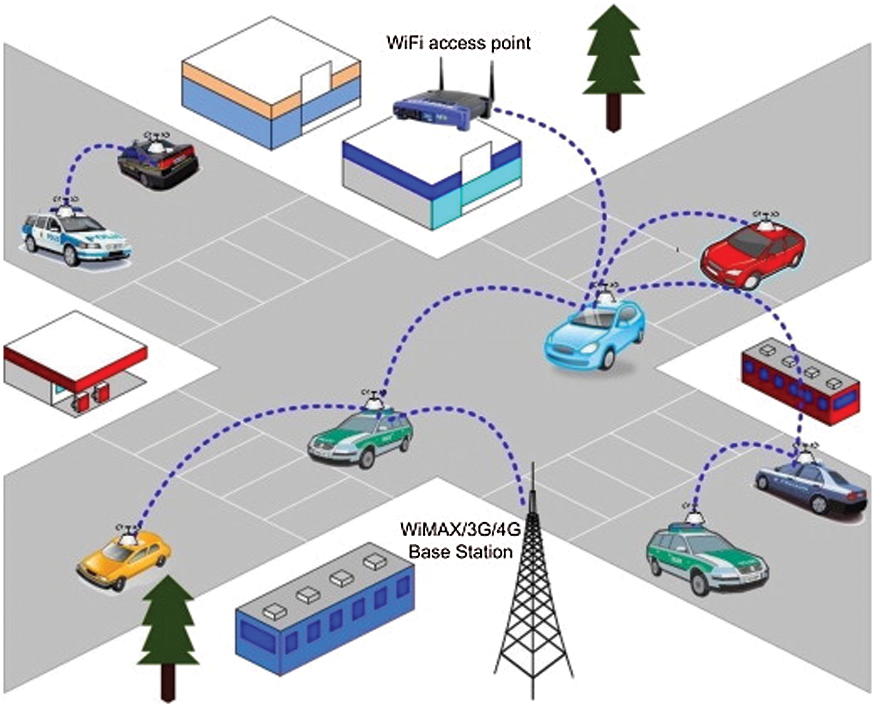
Figure 1: Overview of wireless multi-hop network
Low power utilization of WFDC [4] and FD power saving mode (PSM) [5], turns media on and off conferring to a beacon cycle that decreases power utilization. Though, the power utilization of FD-PSM is lower than FDC, it is higher than HD-PSM [6]. The CSMA based MAC protocol was proposed for the cognitive radio networks [7–9]. The FD-MAC protocol was proposed for single hop wireless network [10]. FD-PSM cannot attain high TP as a result of range transmissions prohibition during a beacon cycle. The main contribution of the paper is PiMAC for FD multihop network.
The remaining sections of the paper are as follows: Section 2–relevant works, Section 3–proposed approach, Section 4–result and discussion, and lastly Section 5–conclusion.
Wi-MAX technology developed bandwidth and bigger range as equated to Wi-Fi primarily based WS. It is a wireless scheme alternative to several current wired back haul and coverage improvements. The IEEE 802.16 has advanced standards for broadband wireless access [11,12] that cater chiefly to 2 styles of usage models.
• IEEE 802.16-mounted users
• IEEE 802.16e-moveable users
Basic MAC system is shown in Fig. 2. The figure shows how to perform link adaptations by first determining whether or not an appropriate backoff window has been reached. Then, using approximation methods, determine the best contention window. The current contention window size should be compared to the back off window size on transmission successes (failures). If the current window size is larger than the back off window, window size is reduced (raised) to allow for more aggressive (conservative) transmission attempts while the link rate is maintained. Otherwise, the transmission rate is bumped up (down) to the next higher (lower) rate. A fixed BWA scheme has a minimum of one Base Station (BS) allotted by numerous Subscriber Stations (SS). Wireless constellation [13] is transmissible from Wi-MAX design and follows parallel MAC machine for interaction among BS and ST. SS is joined to numerous end users with various broadband information with the BS over external antennas. The scheme uses a band of 10–66 GHz because line of sight (LOS) interaction develops the sensible requirement due to shorter wavelength. The BS receives information [14] measure requests from Selective Service System and allows time-slots on transmission channel [15].
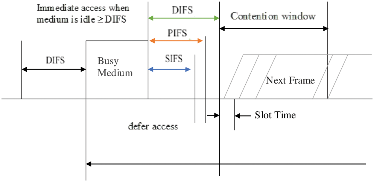
Figure 2: MAC mechanism
The BS may reserve bound time slots on transmission that are accessible to all or any Selective Service System (SSS) for competition. The SSS might use those slots to transmit knowledge or to request for devoted broadcast chances. The transmission channel is split into a stream of mini-slots. A Subscriber Stations that needs to convey on transmission, requests broadcast channels in units of mini-slots. The BS receives requests over a time period and collects a provision MAP message [16,17] unfolding the channel distributions for an explicit amount of long run referred to as the MAP time.
In static MAC protocols, nodes are determined as data channels that are contention-free. Static protocols are integrally non-scalable. In dynamic and ad-hoc schemes, nodes generally use distributed management channel [18,19] over data channels. The 2 major MAC topologies used are unified or dispersed. Dynamic MAC protocols in dispersed topology are contention-based. In PCLS, loosely synchronal style of TDMA with non-overlapping time’s lots has been projected for low capability detector networks.
Chen et al. [20] proposed an extended Hungarian deployment algorithm based on an interference graph to select the deployment sites for mobile relay stations from the candidate positions, with the goal of maximizing energy efficiency while meeting the spectral efficiency requirement and the coverage constraints of mobile users. Minelli et al. [21] studied the extent of battery savings for users transmitting on the uplink by optimising relay node deployment in terms of uplink energy usage per transmit bit, while ensuring a minimum uplink average user delay.
As per [22], AF innovation is less muddled than DF innovation, yet it causes more clamor and impedance at objective gadgets and may force high pinnacle power levels because of by and large sign enhancement, making DF transfer more commonsense, particularly for energy-compelled gadgets, so the unravel and-forward (DF) hand-off convention was utilized.
There are two types of full-duplexing MACs now available: synchronous and asynchronus. Single hop networks are supported by FD-MAC, as previously indicated. To outperform the previous approach, we proposed FD-Pi Mac.
FD scheme is shown in Fig. 3, in which signals can move in both directions at the same time. A HD scheme is a midway among simplex and FD schemes. A walkie-talkie is an instance of this category. When one of the users speaks, the other user must stop talking till the first user ends their turn and the channel is handed-over to the other user.
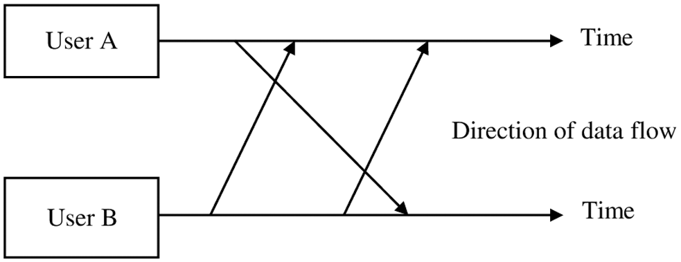
Figure 3: FD system
3.1 Full Duplex- PiMAC Protocols
Some methods of MAC protocols personalized for FD antennas are deliberated. Fig. 4 signifies the wireless interaction through the FD-PiMAC. Concerning FDWC, it can be reviewed in 2 forms [23].
(i) The 3-node unidirectional FDWC (Fig. 4a (Type 1)).
(ii) The 2-nodebidirectional FDWC (Fig. 4b (Type 2)).
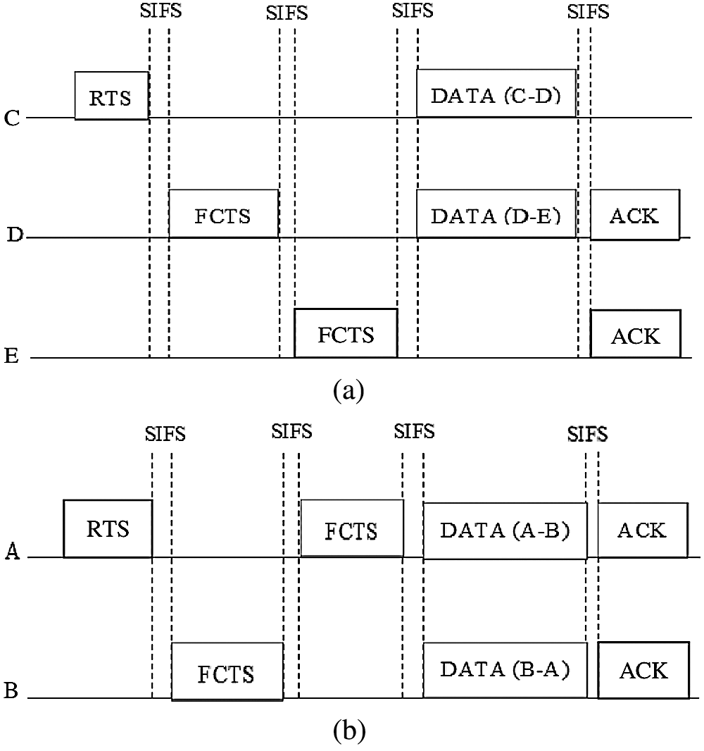
Figure 4: WC using FD-MAC. (a) unidirectional links. (b) type 2: bidirectional links
The most individuality of proposed system is that it uses FCTS frame, which is totally different from clear-to-send (CTS) frame employed in existing system. FCTS frame has 2 terminus arenas and 2 period fields. The 2 destination fields are required to handle public services in Fig. 4a. The FCTS sent from node D instantaneously approves the receipt of RTS from node C and introduces an interaction with node E.
The two period areas face synchronization problems with the network [24], since information packet of size 2 in broadcasts might vary. For instance, in Fig. 4b the information packet A desires to B is bigger than B desires to direct A. Another distinction to existing system is that D introduces an interaction with E¸ employing a FCTS frame. Though the proposed system is in a position to supply a correct interaction underneath FD antenna, it has some drawbacks. Our work aims to beat or to minimize those issues.
3.2 Full-Duplex Pipeline MAC Frames
Fig. 5 displays a typical FD framing structure. The RTS frame is followed by SIFS time and CTS frame
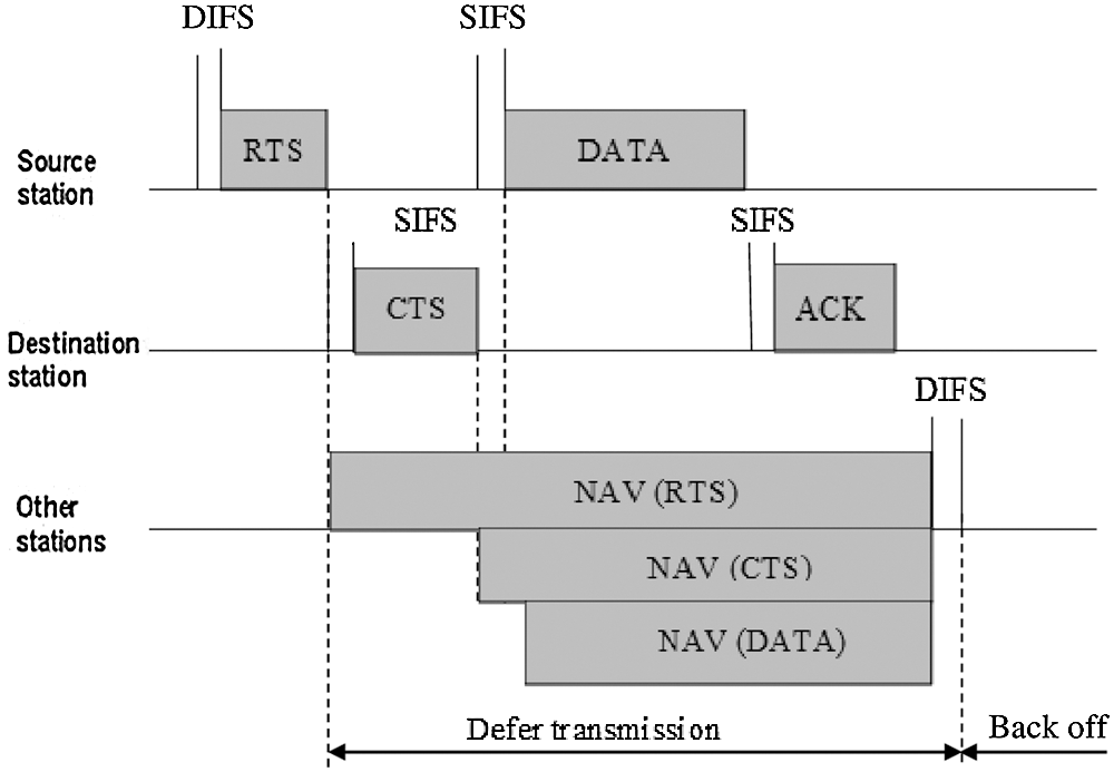
Figure 5: Channel access using RTS/CTS frames
The subsequent timings in µsec are exposed from assessed 802.11a which is shown in Fig. 6.
The pipeline scheduling is classified below,
(a) Parallel pipelines
(b) Dynamic scheduling
(c) Static scheduling
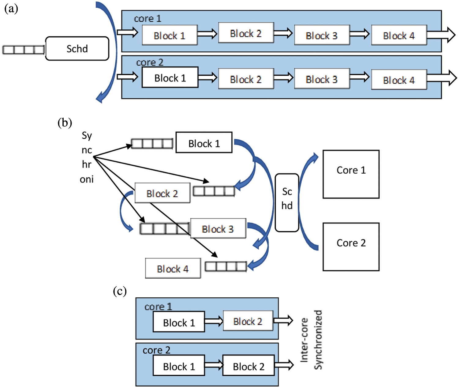
Figure 6: Pipeline scheduling. (a) Parallel pipelines (b) Dynamic scheduling (c) Static scheduling
For 19 Mbps, DIFS = 35 µs, RTS = 37 µs, SIFS = 17 µs, CTS = 33 µs, Data = 705 µs, ACK = 31 µs. Full-Duplex Pipeline MAC frame is shown in Fig. 7. Note that once a FD knowledge broadcasts, the ACK from each node concerned within the FD swap are conveyed at the same time.
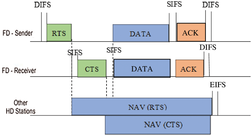
Figure 7: Full-duplex pipeline MAC frames
HD nodes neglect collisions throughout NAV length set by associate degree RTS/CTS; this is often non-standard actions for legacy HD nodes however assist to spotlight the coexistence dynamics. HD nodes are legacy nodes that don’t avoid collisions in NAV length.
A small number of smart jammers dispersed throughout a geographical area in the context of a multihop wireless network can last for a long time with little energy resources. Because they only require brief periods of jamming, the remaining time and energy can be employed to jam other communication channels. They can even work together to construct an attack network that targets traffic between certain nodes. They can accomplish a variety of objectives, including as prohibiting all communication, partitioning a network at a low energy cost, or forcing all packets to be routed across specific locations, [25].
The detachment between the get and communicate recieving wires weakens the self-impedance signal [26], however this recieving wire detachment isn’t sufficient. The key thought behind radio wire scratch-off is to utilize a second communicate recieving wire and spot it with the end goal that the two send signals meddle damagingly at the get radio wire. It is accomplished by having one half frequency distance offset between the two send radio wires. The subsequent damaging obstruction drops 20–30 dB of self-interference. Joined with the simple and computerized scratch-off depicted over, the plan can drop 50–60 dB of self-obstruction, which is adequate to work a full duplex 802.15.4 radio.
4 Simulation Results and Discussion
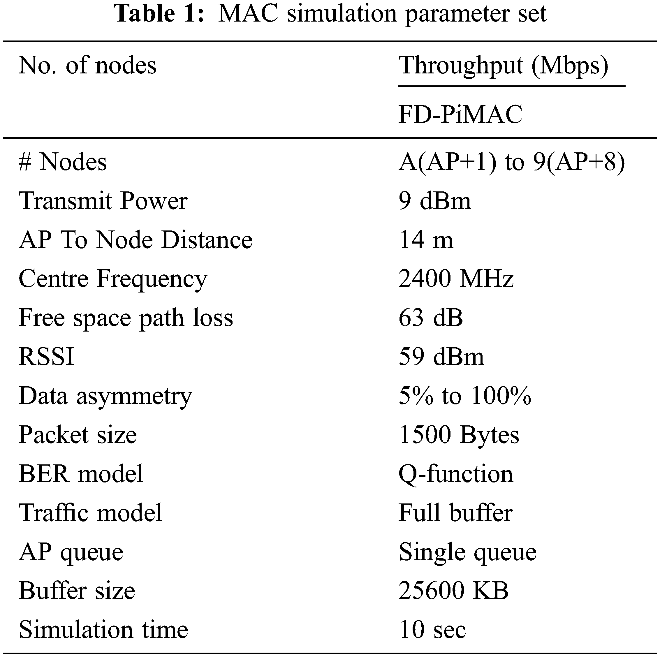
Tab. 1 delivers the simulation parameters used. In all cases, have a tendency to used AP to FD distance departure of 14 m. The free area path loss formula was used to compute the number of path loss. To model bit error rate, we have a tendency to assign that self-interference and thermal noise area unit mathematician, and that we use quality Q-functions for encoded modulation. The utmost packet size is 1500 bytes; there is no separation and every packet are sent as the payload of one FD frame.
Due to reverse development, collisions within the output of proposed system and existing system, our effort consumes the well-known Bianchi’s model, [27]. The systematic description of channel output (S) is,
where,
where,
ptr signifies the probability of at least one broadcast
ps signifies the probability of a broadcast happening during time slot be effective.
These probabilities are reliant to the parameters of exponential Back off procedure and the nodes in the network. When an effective interaction happens, the entire payload (Psz) must be the summation of the payloads of both data interaction. This alteration is due to the fact that data can be sent from A to B and from B to A in the same effective interaction.
The channel throughput (CTP) is measured as:
where Pij—sz signifies the payload of info conveyed from node i to j—. The proposed system uses pulse/tone signals rather than RTS/CTS frames. So, Tc = Tpulse + TDF for proposed system. Tc is lower for proposed system than for existing system, once Tpulse + TDF < TRT + TDF as a result of Tpulse < TRT. So, as each Tc and Ts area unit lower for proposed system than for existing system [28], it’s estimated that Tslot is lower for proposed system.
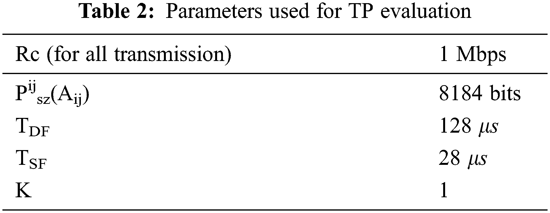
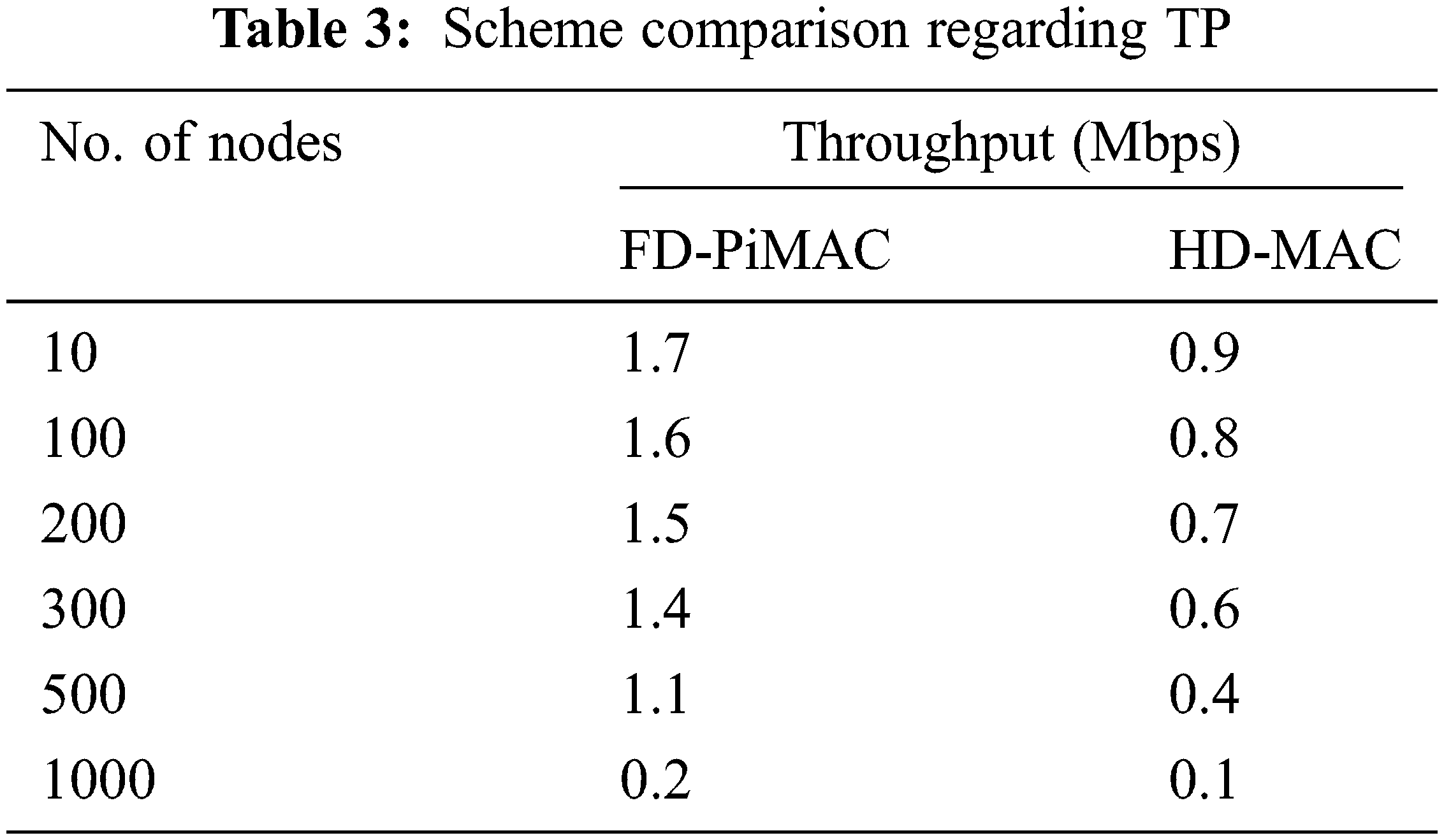
The output for numerous ranges of nodes is calculated once using the existing system and the proposed system. For this computation, the parameters utilized in Tab. 2 were used. The scale of physical and MAC layer headers in addition as back off window parameters were similar as outlined in IEEE 802.11b. As may be ascertained, proposed system outperformed up to 87% and 91%. The advantage of using-MAC will increase the range of nodes. Also proposed system takes benefit of the FD mode of the antenna, which outperforms additionally 80% for all assessed cases, [29]. In this analysis, it was considered of that Psz = 8184 bits and Rc = 1Mbps; that’s, TDATA represents an excellent portion of total UTC. If a lower packet size and/or the next broadcast rate are taken into account, the gain of proposed system would be still advanced. Also, it is often determined that for ð‘› = 10 the CTP is near to the utmost TP calculated and given in Tab. 3. However, CTP attains values above TP. This occurs because upper the quantity of nodes, the upper probability of collisions.
The CTP values computed for existing system and proposed system are equated with first values. This evaluation is done to the point out the consistency of computations. Once the computed values of existing system and proposed system area unity or terribly near to the first ones, they consume TP vs. probability p rather than quantity of nodes. The n signifies quantity of nodes and their p has a similar that means that,
An instance of evaluation is going to be conferred next. In computations, for n = 10, ptr is adequate to 0.33 and σœ = 0.039. Note that CTP values for each proposed system and existing system for p = 0.039 are terribly about to conferred values. For n = 10 and the channel throughput vs. transmission probability measures is shown Tab. 4.
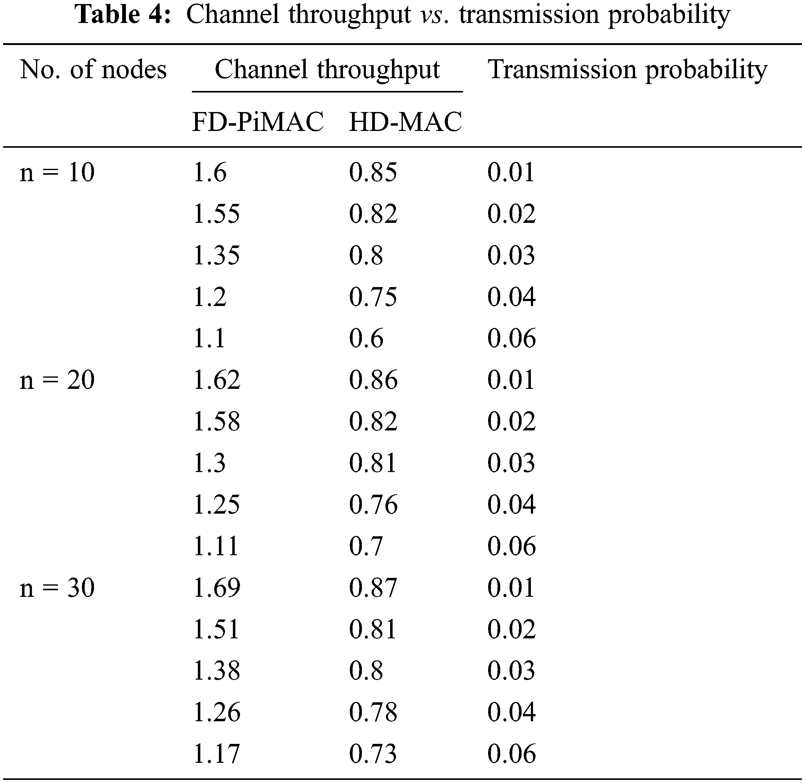
From the Tab. 4, existing system CTP is slightly above 0.8 Mbps whereas proposed system CTP nearly reaches 0.6 Mbps.
4.2 Ideal Low Power and Energy FD Communication
Tab. 5 displays the power utilization. It based on no. of nodes and power. Here, power utilization of proposed system and existing system methods are given.
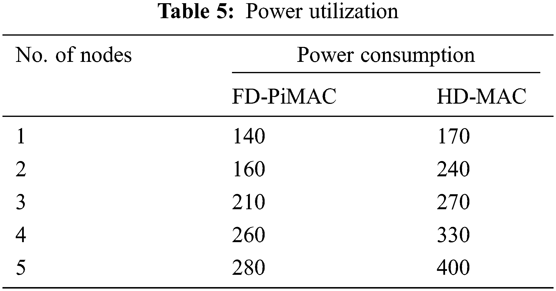
Here, power utilization of proposed system and existing system methods have been compared. From the graph, it is visually noticed that, the power consumption of proposed system method is reduced by 20% when compared with the existing system method. It shows that the proposed method consumed low range power.
Fig. 8 displays the graphical representation of energy utilization. It based on number of nodes and energy. Here, energy utilization of proposed system and existing system methods has been compared. From the graph, it is visually noticed that, the energy consumption of proposed system method is 29.8% reduced when compared with existing system method, its comparison is shown in Fig. 9. It shows that the proposed method consumed low range energy.
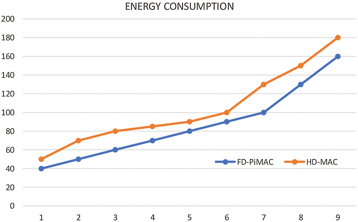
Figure 8: Graphical representation of energy utilization
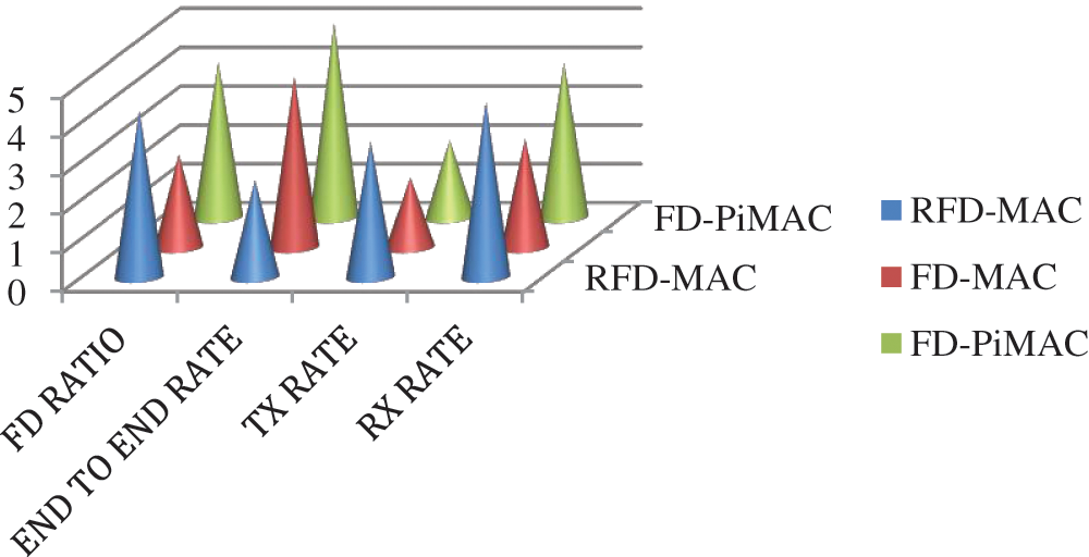
Figure 9: Comparison of PiMAC with existing techniques
The proposed FD-PiMAC was compared with FD-MAC and RFD-MAC based on transmission parameters say FD ratio, tx rate etc., and found, PiMAC to outperform other methods.
For FD relaying in MWN, we proposed a pipelined MAC protocol, to unravel some necessary issues with existing WS. Experiments on real nodes show that FD theme achieves a median gain of 90% in mixture throughput as compared to HD theme for an MWN. The system additionally discusses potential MAC and throughput with FD. It suggests ways in which a FD system will solve some necessary issues with existing WS as well as transmission, loss of throughput because of congestion, transmission probability, power consumption and energy consumption. Here, the energy and power utilization of FD-PiMAC and HD-MAC methods have been compared. From the graph, it is visually noticed that, the energy and power consumption of FD-PiMAC method is reduced when compared with HD-MAC method. It shows that the proposed method consumed low range energy. The execution and trial results specify that PiMAC protocol considerably develops network implementation in terms of TP and transmission delay. The power, energy consumption of proposed system method is reduced when compared with the existing system method. It shows that the proposed method consumed low range power and energy. Finally, the necessities and analysis problems for planning of FD-MAC protocols are highlighted.
Acknowledgement: The authors would like to thank Anna University and also, we like to thank anonymous reviewers for their so-called insights.
Funding Statement: The authors received no specific funding for this study.
Conflicts of Interest: The authors declare that they have no conflicts of interest to report regarding the present study.
1. H. Bevrani, T. Hiyama and H. Bevrani, “Robust PID based power system stabilizer: Design and real-time implementation,” International Journal of Electrical Power & Energy Systems, vol. 33, no. 2, pp. 179–188, 2011. [Google Scholar]
2. M. Duarte, A. Sabharwal, V. Aggarwal, R. Jana, K. K. Ramakrishnan et al., “Design and characterization of a full-duplex multi- antenna system for Wi-Fi networks,” IEEE Transactions on Vehicular Technology, vol. 63, no. 3, pp. 1160–1177, 2014. [Google Scholar]
3. A. Appathurai and P. Deepa, “Radiation induced multiple bit upset prediction and correction in memories using cost efficient CMC,” Informacije MIDEM, vol. 46, no. 4, pp. 257–266, 2016. [Google Scholar]
4. K. Tamaki and T. Watanabe, “Full duplex media access control for wireless multi-hop networks,” in Proc. Vehicular Technology Conf., Dresden, Germany, IEEE, pp. 1–5, 2013. [Google Scholar]
5. W. Zhou, K. Srinivasan and P. Sinha, “RCTC: Rapid concurrent transmission coordination in full duplex wireless networks,” in Proc. Int. Conf. on Network Protocols, Goettingen, Germany, IEEE, pp. 1–10, 2013. [Google Scholar]
6. S. Goyal, P. Liu and S. Panwar, “A distributed MAC protocol for full duplex radio,” in Proc. Asilomar Conf. on Signals, Systems and Computers, Pacific Grove, CA, USA, IEEE, pp. 788–792, 2013. [Google Scholar]
7. S. Sen, R. R. Choudhury and S. Nelakuditi, “CSMA/CN: Carrier sense multiple access with collision notification,” IEEE Transactions on Networking, vol. 20, no. 2, pp. 25–36, 2011. [Google Scholar]
8. A. Appathurai and P. Deepa, “Design for reliability: A novel counter matrix code for FPGA based quality applications,” in Proc. Symp. on Quality Electronic Design, Kula Lumpur, Malaysia, IEEE, pp. 56–61, 2015. [Google Scholar]
9. Y. Zhang, B. Hu and S. S. Ramaiah, “FD-MMAC: Combating multi-channel hidden and exposed terminals using a single transceiver,” in Proc. Conf. on Computer Communications, Toronto, Canada, IEEE, pp. 2742–2750, 2014. [Google Scholar]
10. D. Nguyen and M. L. Aho, “On the spectral efficiency of full-duplex small cell wireless systems,” IEEE Transactions on Wireless Communications, vol. 13, no. 9, pp. 4896–4910, 2014. [Google Scholar]
11. K. Tamaki and T. Watanabe, “Full duplex media access control for wireless multi-hop networks,” in Proc. Vehicular Technology Conf., Dresden, Germany, IEEE, pp. 1–6, 2013. [Google Scholar]
12. A. Ahilan, G. Manogaran and N. Chilamkurti, “Trusted FPGA-based transport traffic injects, impersonate (I 2) attacks beaconing in the internet of vehicles,” IET Networks, vol. 8, no. 3, pp. 169–178, 2019. [Google Scholar]
13. T. Vermeulen and S. Pollin, “Energy-delay analysis of full duplex wireless communication for sensor networks,” in Proc. Global Communications Conf., Austin, TX, USA, IEEE, pp. 455–460, 2014. [Google Scholar]
14. H. A. Salam and B. M. Khan, “Use of wireless system in healthcare for developing countries,” Digital Communications and Networks, vol. 2, no. 1, pp. 35–46, 2016. [Google Scholar]
15. L. D. M. Guimaraes and J. L. Bordim, “Full-duplex MAC tailored for 5G wireless networks,” Wireless Communications and Mobile Computing, vol. 11, pp. 23–29, 2018. [Google Scholar]
16. M. Thoppian, S. Venkatesan and R. Prakash, “CSMA-based MAC protocol for cognitive radio networks,” in Proc. Int. Symp. on a World of Wireless, Mobile and Multimedia Networks, Espoo, Finland, IEEE, pp. 1–8, 2007. [Google Scholar]
17. Y. Song, W. Qi, W. Zhao and W. Cheng, “Full-duplex MAC protocol for CSMA/CA-based single-hop wireless networks,” Sensors, vol. 19, no. 10, pp. 2413–2218, 2019. [Google Scholar]
18. P. K. Sahoo, S. R. Pattanaik and S. L. Wu, “A novel synchronous MAC protocol for wireless sensor networks with performance analysis,” Sensors, vol. 19, no. 24, pp. 5394–5399, 2019. [Google Scholar]
19. R. Dhaya, R. Kanthavel and A. Ahilan, “Developing an energy-efficient ubiquitous agriculture mobile sensor network-based threshold built-in MAC routing protocol (TBMP),” Soft Computing, vol. 1, no. 18, pp. 1–10, 2021. [Google Scholar]
20. H. Chen, W. Chen and F. Zhao, “Energy-efficient mobile relay deployment scheme for cellular relay networks,” Ad Hoc Networks, vol. 51, no. Apr. (13), pp. 36–46, 2016. [Google Scholar]
21. M. Minelli, M. Ma, M. Coupechoux, J. M. Kelif, M. Sigelle et al., “Uplink energy-delay trade-off under optimized relay placement in cellular networks,” IEEE Transactions on Mobile Computing, vol. 15, no. 9, pp. 2376–2387, 2016. [Google Scholar]
22. K. Ishibashi and H. Ochiai, “Analysis of instantaneous power distributions for non-regenerative and regenerative relaying signals,” IEEE Transactions on Wireless Communications, vol. 11, no. 1, pp. 258–265, 2011. [Google Scholar]
23. Z. F. Liao, J. B. Liang and C. C. Feng, “Mobile relay deployment in multihop relay networks,” Computer Communications, vol. 112, no. 1, pp. 14–21, 2017. [Google Scholar]
24. M. Long and X. Xiao, “Outage performance of double-relay cooperative transmission network with energy harvesting,” Physical Communication, vol. 29, no. 2, pp. 261–267, 2018. [Google Scholar]
25. J. Wang, Y. Gao, X. Yin, F. Li and H. J. Kim, “An enhanced PEGASIS algorithm with mobile sink support for wireless sensor networks,” Wireless Communications and Mobile Computing, vol. 3, no. 8, pp. 22–31, 2018. [Google Scholar]
26. B. Xiong, K. Yang, J. Zhao, W. Li and K. Li, “Performance evaluation of open flow-based software-defined networks based on queueing model,” Computer Networks, vol. 102, no. 2, pp. 172–185, 2016. [Google Scholar]
27. J. Wang, Y. Gao, W. Liu, A. K. Sangaiah and H. J. Kim, “An intelligent data gathering schema with data fusion supported for mobile sink in wireless sensor networks,” International Journal of Distributed Sensor Networks, vol. 15, no. 3, pp. 1550, 2019. [Google Scholar]
28. M. Duarte, “Full-duplex wireless: Design, implementation and characterization,” PhD. dissertation, Rice University, Houston, Texas, 2012. [Google Scholar]
29. R. Ramanathan and R. R. Hain, “Topology control of multihop wireless networks using transmit power adjustment,” in Proc. Conf. on Computer Communications, Tel Aviv, Israel, IEEE, vol.2, pp. 404–413, 2000. [Google Scholar]
 | This work is licensed under a Creative Commons Attribution 4.0 International License, which permits unrestricted use, distribution, and reproduction in any medium, provided the original work is properly cited. |