DOI:10.32604/csse.2022.019149
| Computer Systems Science & Engineering DOI:10.32604/csse.2022.019149 | |
| Article |
Hybrid Renewable Energy Source Combined Dynamic Voltage Restorer for Power Quality Improvement
Electrical Engineering Department, College of Engineering, Prince Sattam Bin Abdulaziz University, Wadi Aldawasir, 11991, Saudi Arabia
*Corresponding Author: N. Kanagaraj. Email: k.gonder@psau.edu.sa
Received: 04 April 2021; Accepted: 10 May 2021
Abstract: In this paper, the hybrid photovoltaic-thermoelectric generator (PV-TEG) combined dynamic voltage restorer (DVR) system is proposed for the power quality disturbances compensation in a single-phase distribution system. The stable and precise level of input voltage is essential for the smooth and trouble-free operation of the electrically sensitive loads which are connected at the utility side to avoid system malfunctions. In this context, the hybrid PV-TEG energy module combined DVR system is proposed in this paper. With the support of the hybrid energy module, the DVR will perform the power quality disturbances compensation effectively with needed voltage and /or power. In the proposed system, the PV and TEG energy sources are connected electrically in series to produce adequate voltage for the DVR operation and the fractional factor-based variable incremental conduction (FFVINC) maximum power point tracking (MPPT) control algorithm is employed to extract the possible maximum power from the PV array. The intelligent fuzzy logic controller (FLC) is chosen for implementing the MPPT control algorithm. The half-bridge voltage source inverter (VSI) circuit and in-phase voltage compensation technique are used in the DVR for better power quality disturbances compensation. The performance and usefulness of the proposed DVR system are investigated by an extensive simulation study with four different modes of operation, the study results are confirmed that the proposed system promptly identifies the power quality disturbances for compensation. Moreover, the investigation proved that the combined PV and TEG energy module can provide better energy efficiency in converting solar irradiation into electricity.
Keywords: Power quality compensation; MPPT; hybrid energy module; DVR
Nowadays, sensitive electrical and electronic loads are widely used for network communication, computing, safety and monitoring in residential as well as commercial buildings. The sensitive loads which are connected in the distribution supply system are mainly affected by the power quality disturbances, which leads to various system malfunctions such as data losses, system halts, communication interference, reducing the life period of the equipment etc. To overcome such a kind of malfunctions, the voltage level of the distribution system must be maintained correctly [1–3]. Voltage swells, voltage sags and outage type power quality issues have adverse effects on the system functioning [4–8]. Recently, custom power devices are widely preferred for maintaining the power quality of the supply, the IEEE standard “IEEE Std. 519” [9] recommends many custom power devices that can be installed at the utilization side to protect the consumer devices. The DVR is one of the custom power devices which is used for improving power quality. The DVR is a voltage source inverter made up of IGBTs and connected at the utility side in series between the load and source supply. The DVRs are used to protect the sensitive loads from voltage disturbances by injecting the compensating voltage into the supply line. However, the DVR needs adequate real and reactive power for the deep and long-period voltage compensation, the energy storage devices used in the DVR system is not enough sometimes for such type of voltage compensation due to the limited energy storage facility. Suppose the renewable energy source is added in the DVR system, the deep and long-period voltage compensation can be made easily. Further, renewable energy sources will continuously charge the energy storage devices connected with the DVR system by which additional power can supply to the consumer load. Recently, the DVR systems which are integrated with renewable energy sources such as PV, wind power, fuel cells etc. were confirmed their ability for better power quality compensation [10–13].
The uses of renewable energy resources for electric power generation are essential to supply the required power for the increasing electricity demand and protect the environment [14–17]. Presently, the standalone PV modules are installed in many residential and commercial buildings to obtain the required power directly from solar energy. The drawback in the use of PV module is the low power conversion efficiency when compared to capital investment. One of the reasons for low efficiency is the PV cells utilize only a limited amount of solar incident irradiation energy for electric power generation and most of the solar irradiation energy is converted into waste heat energy [18]. Also, the waste heat will increase the PV cell temperature which results in the energy conversion capability of the PV cell will decrease at a considerable level [19]. Several developments have been made recently to improve the power conversion efficiency of the PV array [20–22]. The temperature of the PV cell can be reduced by fixing the TEG and heat sink set-up on the backside of the PV panel which will reduce the PV cell temperature and extra power can be produced [23]. Therefore, in the TEG combined PV energy module the TEG will make use of the waste heat around the PV panel for extra power generation by which the overall system power conversion efficiency could be improved.
The appropriate control topology is also essential for the DVR to decide the proper magnitude and phase of the injecting voltage to retain the magnitude and phase of the load voltage. Various control strategies and circuit configurations have been suggested in the literature [24–32]. The popular control techniques are (i) in-phase voltage sag/swell compensation (ii) pre-sag voltage compensation and (iii) zero active power injection method. When compared to other techniques, the in-phase voltage compensation technique needs only minimum voltage injection for the voltage swells or sag compensation [33]. The various DVR control techniques and topologies have been discussed in Nielsen et al. [34]. Control strategies applied to mitigate the voltage disturbances and harmonics are proposed in Refs. [10,35]. The intelligent FLC-based DVR techniques for voltage compensation and reduce the total harmonics distortion (THD) has been suggested in Refs. [11–13]. The voltage disturbance elimination using transformerless DVR topologies were discussed in Refs. [36,37].
In this paper, the H-bridge VSI circuit-based DVR with a hybrid PV-TEG renewable energy module is proposed for compensating the power quality disturbances of the sensitive loads connected in a single-phase distribution system. The proposed DVR system is designed that to compensate deep and long-term voltage disturbances by supplying adequate real and reactive power from the PV-TEG hybrid energy source. Also, the energy conservation mode of the DVR will conserve the customer energy consumption from the utility grid which results in the potential panel tariff for the consumers could be reduced at a reasonable level. A low power DC-DC converter is chosen to extract the maximum power generated on the PV array and a coupled inductor based high step-up DC-DC boost converter is used to amplify the DC voltage suitably for the H-bridge VSI circuit. The in-phase compensation method is employed in the DVR to mitigate the various types of voltage disturbances that occurred in the low voltage power distribution system. The simulation study of the proposed DVR system is carried out under various operating modes to demonstrate its effectiveness.
2 The Proposed DVR System Configuration
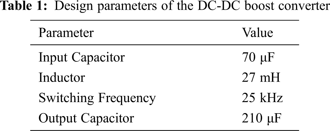
The schematic of the proposed PV and TEG combined single-phase DVR system for the power quality disturbances compensation is shown in Fig. 1. In the PV-TEG hybrid energy module, the TEG is fixed on the backside of the PV array, the heat sinks are arranged at the cold side of the TEG. Moreover, the heat sink arrangement will reduce the PV panel temperature at a considerable level which improves the performance of the PV array in terms of energy conversion efficiency. The PV and TEG are connected electrically in series to provide adequate voltage to the DVR system for the high amplitude voltage compensation. The MPPT algorithm is used only for the PV module in the proposed system by considering its maximum power contribution to the load, the PV module contributes about 90% of the total load requirement. A continuous current mode DC-DC boost converter is designed based on the procedure in Rashid [38], the converter will harvest the maximum power from the PV array with the support of the proposed FFVINC MPPT control algorithm. The boost converter design parameters are shown in Tab. 1. The converter adjusts the voltage parameter of the PV module based on the duty cycle generated by the MPPT control algorithm to attain the maximum power output.
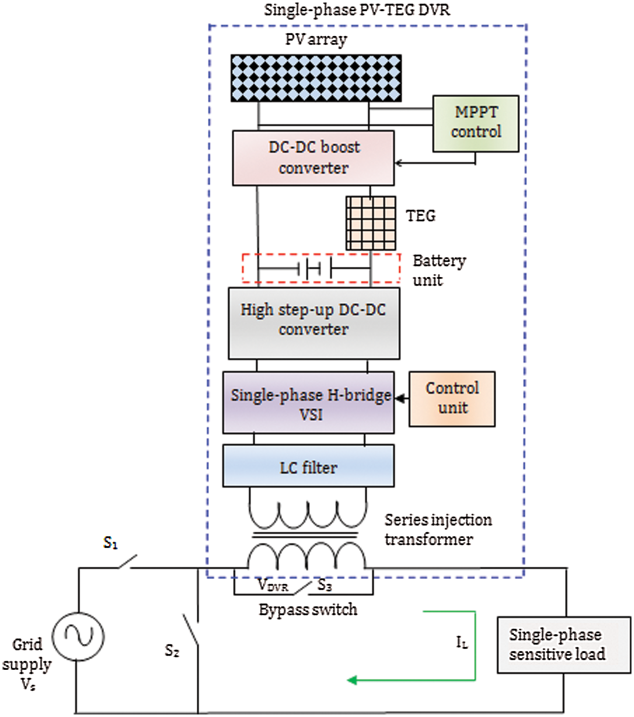
Figure 1: The schematic of the hybrid PV-TEG integrated DVR
The PWM technique-based H-bridge VSI circuit of the DVR converts the DC-link voltage into a sinusoidal AC voltage at the required amplitude and frequency. The H-bridge VSI inverter is the most suitable inverter for the single-phase DVR system due to its simplicity. The circuit configuration of the VSI is shown in Fig. 2, if the switches Q1 and Q2 are ON, the input voltage Vdc will be transfer to the load similarly, if the switches Q3 and Q4 are ON, –Vdc will be transferred to the load. The Low Pass Filter (LPF) added in this circuit will eliminate the unwanted higher-order harmonics present in the VSI output and make a pure sinusoidal waveform suitable for the load voltage compensation [39]. The rated DC-link voltage is set as 300 V for the proposed single-phase DVR. The maximum amplitude of the square wave is given as
The output voltage can be expressed in the following Eqs. (2) and (3)
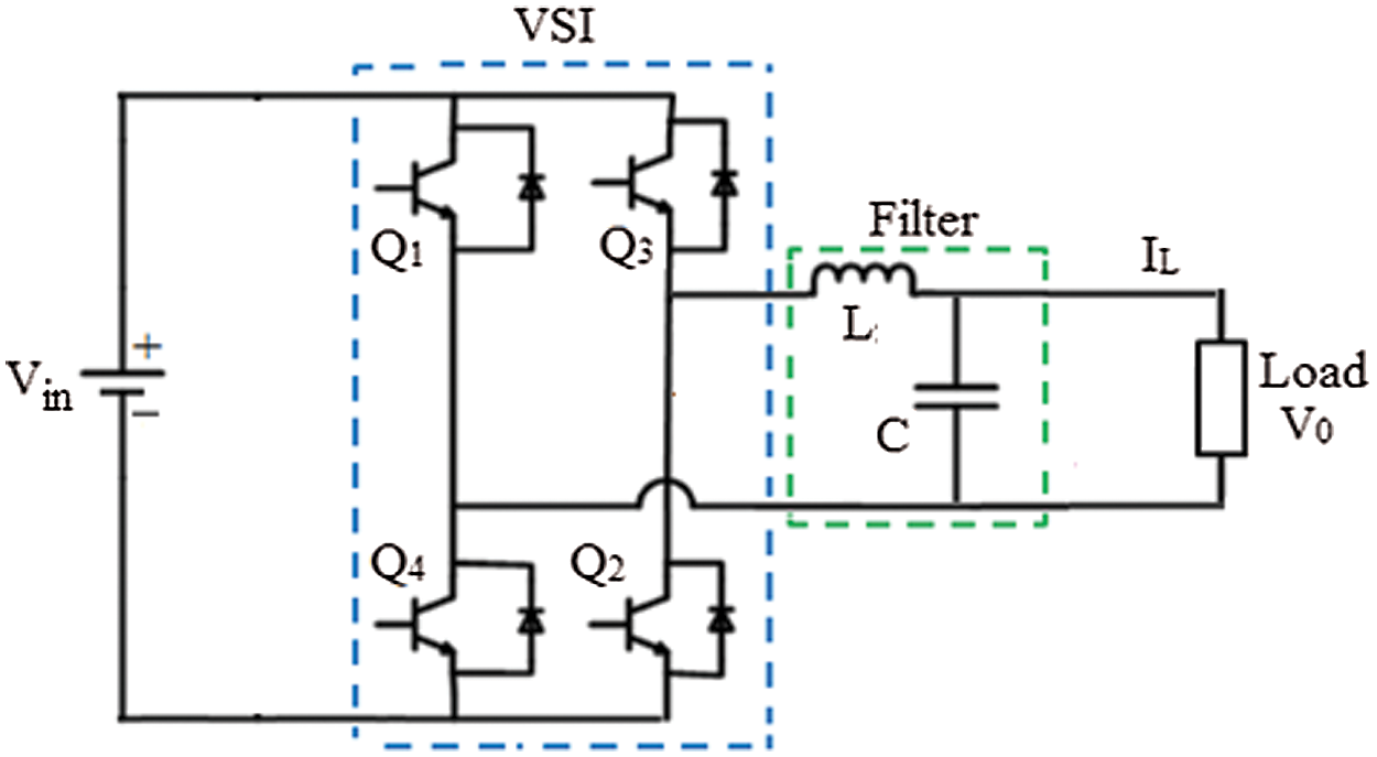
Figure 2: A typical H-bridge VSI circuit diagram
The controller unit for the VSI circuit is depicted in Fig. 3. The voltage disturbance identification in a single-phase distribution system is made by the DVR controller unit. The phasor of the gridline voltage is tracked using a phase-locked loop (PLL) unit to perform the park’s transformation. The supply voltage per unit value is changed into |VS| then it is compared with the reference (Vref) value to generate an error (e) signal. The proportional-integral (PI) controller produces an angle delta (δ) to reduce e to 0. The reference voltage generator produces the Uref signal for the PWM generator using the angle δ, the pulse output of PWM generator is applied to VSI circuit. The detailed operation of the VSI controller can be found [10]. The voltage injection transformer of the DVR will inject the required voltage at the utility side to eradicate the voltage disturbances. The turns ratio of the injection transformer is selected based on the required secondary voltage which is equal to the grid supply voltage. If the secondary voltage of the injection transformer and the distribution system voltage are equal, then the DVR can perform full voltage compensation [40]. The circuit diagram and control methodology of the high step-up DC-DC boost converter circuit is shown in Fig. 4; the DC voltage of 24 V is boosted into 300 V in the present system.
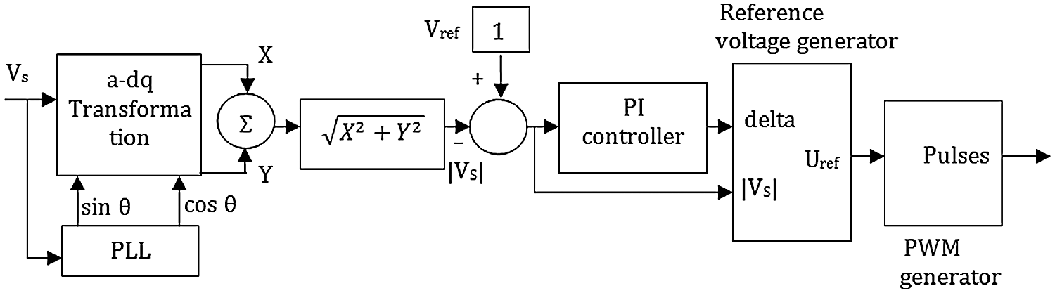
Figure 3: The controller configuration for the VSI circuit
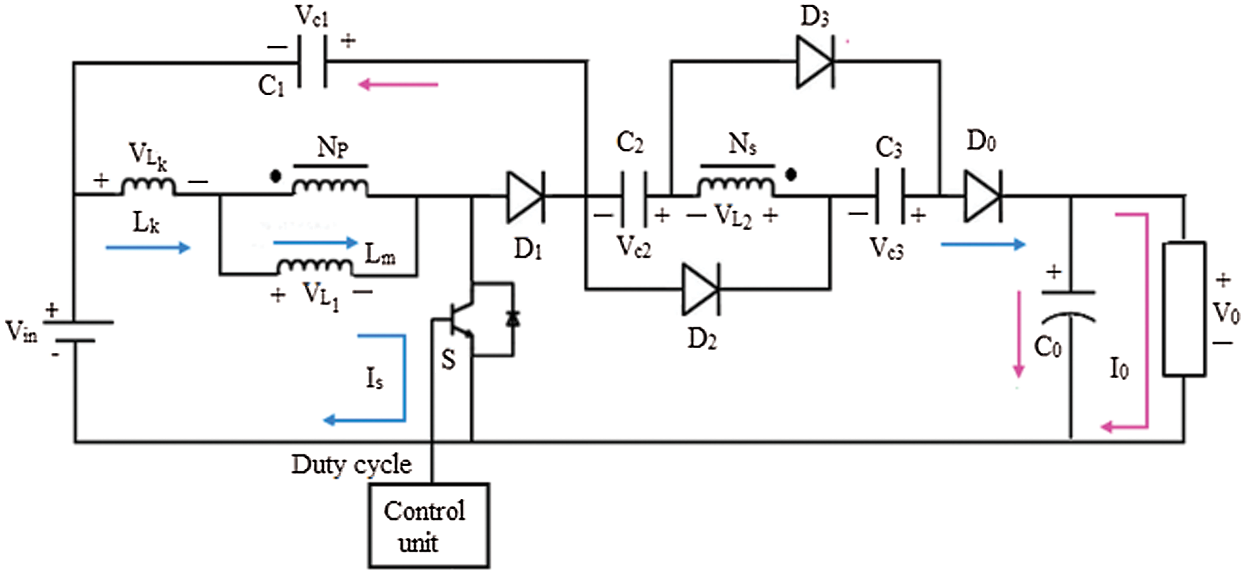
Figure 4: The high step-up DC-DC boost converter
If S is turned ON, the input voltage Vin will charge the inductor Lm at the same time the coupled inductor induces a voltage on the secondary (Ns). The voltage (VL2) of the coupled inductor allows Vin, Vc1, Vc2 and Vc3 to provide sufficient energy to the load in series. The load voltage Vo can be expressed as
where Vc1, Vc2 and Vc3 are the voltages across the capacitor C1, C2 and C3, respectively. The current flow takes in the converter circuit when the switch S is closed is illustrated in Fig. 5. If S is turned OFF, the inductor Lm will release the stored energy through Ns to charge the capacitors C2 and C3. The current flow that takes place in the converter during switch S is OFF is depicted in Fig. 6.
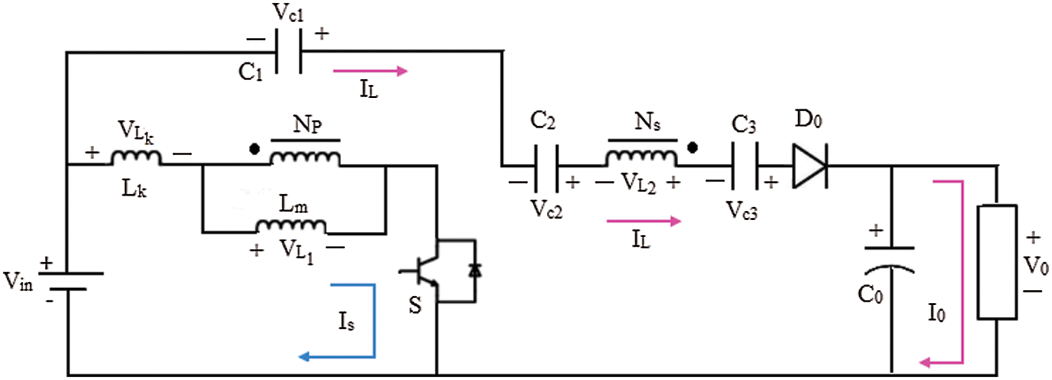
Figure 5: The high set-up DC-DC boost converter configuration when the switch S is closed
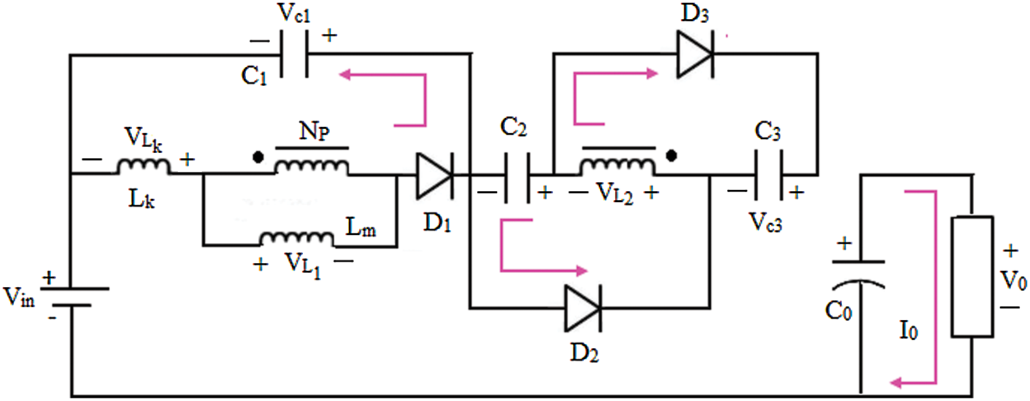
Figure 6: The high set-up DC-DC boost converter configuration when the switch S is open
The capacitors C2 and C3 voltage is given as
where D is the duty cycle, k is the coupling coefficient and n is the turns ratio of a coupled inductor. The PI controller of the control unit will produce the required gate pulses to operate the switch S. The capacitor and inductor values are chosen based on the load current and voltage drop, a detailed design procedure can be found in Hsieh et al. [41].
3 Modeling of the PV Cell and TEG
The PV cells are usually connected in parallel and series form in a PV array, the PV cell generates the electricity directly from the solar irradiation [42]. The equivalent circuit of the PV cell can be represented with a single diode as shown in Fig. 7. Based on the equivalent circuit, the current flow out of the PV cell (Ipv) can be represented using Kirchhoff’s current law,
where Iph is the photocurrent in A, ID is the diode current in A. The current flow through the diode can be expressed using the Shockley diode equation,
Now the Eq. (7) can be rewritten as
The current flow through the diode is negligible during the short-circuit condition so the current Ipv is approximately equal to Isc. By considering the parallel and series-connected PV cells the above expression can be expressed as
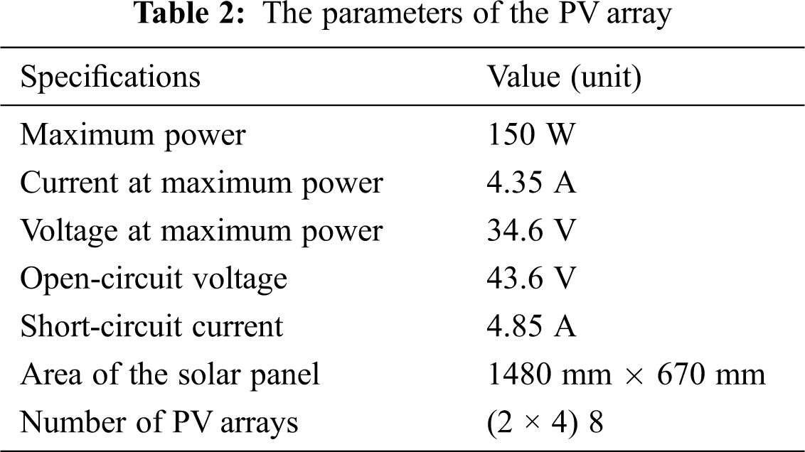
where Isat is the reverse saturation current in A, Vpv denotes voltage output in V, q denotes the electron charge in C, k represents the Boltzmann constant in JK–1, T denotes the cell junction temperature in K, A denotes the ideality factor of the diode, ns and np are the numbers of series and parallel-connected PV cells, respectively. The model of the PV array is developed based on the theory discussed above and the important design parameters are shown in Tab. 2.
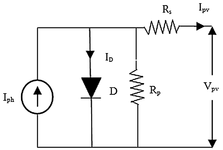
Figure 7: A typical PV cell equivalent circuit
TEG converts the thermal energy directly into electricity based on the theory of the Seebeck effect. The structure of a typical TEG is shown in Fig. 8. The open-circuit voltage of the TEG is given as [43]
where S denotes the Seebeck coefficient in V/K, Tc and Th are the cold-end and hot-end temperatures respectively in K. The power output of the TEG module can be calculated by
where Rint and RL are the internal resistance of the TE and load resistance in ohm, respectively.
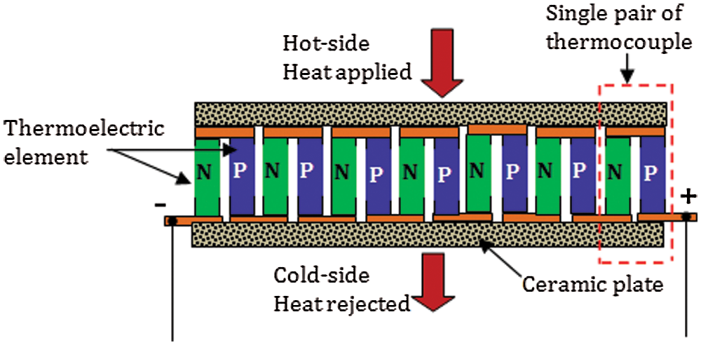
Figure 8: A typical internal structure of the TEG
The model of the TEG is developed based on the thermal and electrical properties of the bismuth telluride Bi2Te3 type thermocouple and the model parameters are shown in Tab. 3. The electrical characteristics of the designed TEG model such as open-circuit voltage (Vteg), load voltage (VT) and output power (Pteg) are plotted for the temperature difference (ΔT) of 0 to 50 K as shown in Fig. 9. To validate the designed model, the parameters’ response of Fig. 9 is compared with the numerically calculated values (Tab. 3), the comparison confirms that there is no significant variation between the designed model output and numerically calculated values, which confirms the accuracy of the designed TEG model.
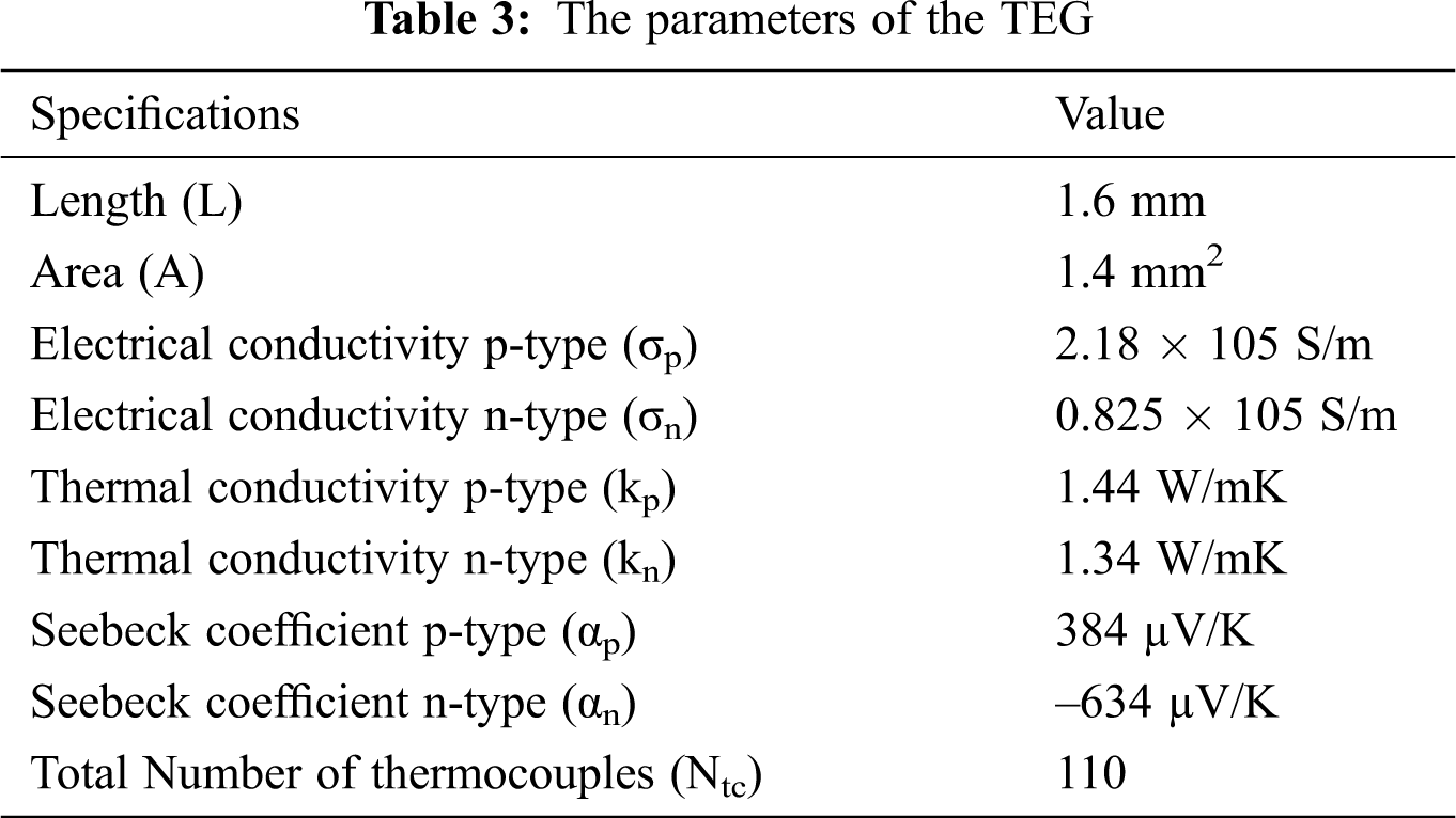
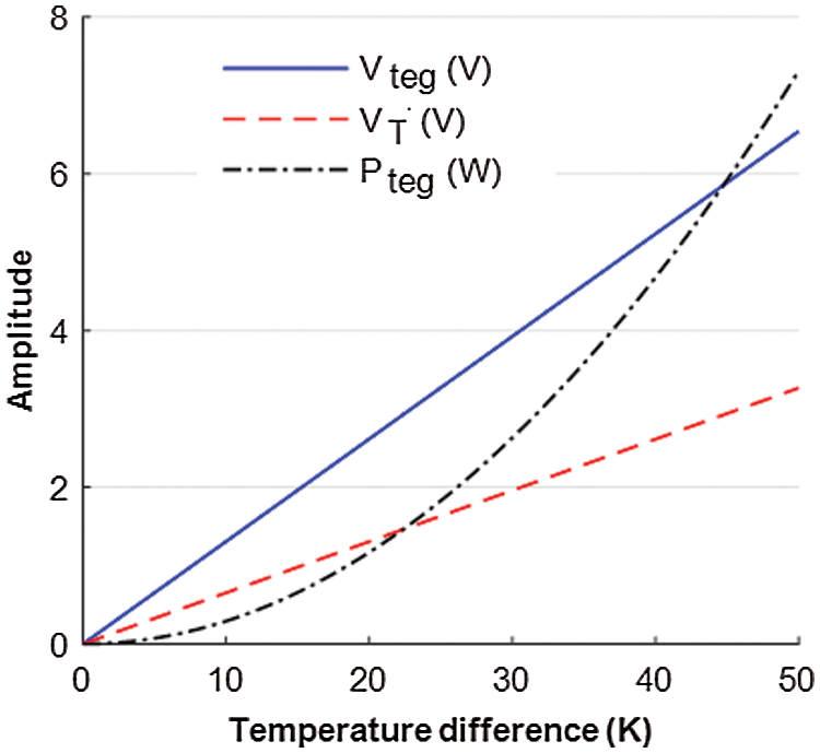
Figure 9: The electrical characteristic of the TEG
4 The Proposed MPPT Control Algorithm
The FFVINC type maximum power tracking control algorithm is proposed in this paper to overcome the drawbacks of the conventional incremental conduction (INC) MPPT control algorithm. The control strategy of the proposed FFVINC technique will use a larger step size for tracking the maximum power point (MPP) when the operating point of the PV is not closer to the optimum level in the P-V curve, the step size will be gradually reduced when the PV array operating point is approaching the peak point of maximum power level. A variable factor (β) used in this control algorithm supports the FLC to produce the variable tracking step size based on the PV operating condition. The value for the β is set between 0 to 1 using the difference in present instant voltage (Vpv) and previous instant voltage (Vpv (t–1)) of the PV array. The difference in voltages is zero then β is equal to 1 otherwise, β will be between 0 and 0.9 based on the magnitude of the voltage difference. The variable factor β will modify the error input of the FLC by which the variable tracking step size is achieved. The concept to use the variable factor for the proposed method is developed from the fractional calculus [44–46]. The general fractional order differentiator can be expressed using the theory of fractional calculus as [47].
where γ() denotes γ function and β denotes the order of the derivative in the range of 0 < β ≤ 1. When β is 0 < β < 1, then the control scheme will be a fractional order control. Otherwise, if β = 1, the control scheme becomes a conventional integer order control. Therefore, the variable factor β can be applied in the MPP tracking scheme to achieve the variable tracking step size which leads to an enhanced MPP tracking performance in terms of speed and accuracy. Using the fractional order differentiator Eq. (13), the variable order INC is given in Eq. (14). A detailed derivation about the variable order INC can be found in Lin et al. [47].
where Ppv and Ppv(t–1) are the present and previous moment PV array power output in W, Vpv and Vpv(t–1) are the present and previous moment voltage output. From Eq. (15), it is noticed that the factor β will influence the power and voltage parameters variation, further this Eq. can be considered as a reasonable approximation of fractional order calculus. The Eq. (15) becomes a general first-order derivative if β = 1, otherwise it is considered as the variable fractional order if 0 < β < 1. So incremental changes in the voltage and power are expressed as
Now the variation in power output to the voltage variation in unit time is represented by
Using the factor β, the Eq. (18) is rewritten as
The change in power (ΔP) of the PV array in unit time is given as
Eq. (19) corresponding to the error calculation, when the factor β is equal to 1 which confirms that the MPP of the PV array is achieved. If MPP is not achieved then β is 0 < α < 1, this is the case the controller must apply an appropriate control action to move the PV operating point towards the MPP. The FLC uses the error (19) and change in power (20) as the inputs and generates output u(t) based on the pre-defined fuzzy control rules. The control strategy of the proposed control algorithm for the MPPT is illustrated in Fig. 10.
5 Implementation of the Proposed DVR System
The main purpose of the proposed DVR system is to maintain supply power quality for the sensitive loads to avoid malfunctions. This can be achieved by injecting a dynamically controlled voltage (VDVR) generated by a forced commutated VSI, the voltage injection to the utility grid line is made using a series-connected voltage injection transformer.
5.1 The Operational Modes of the Proposed DVR
The overall DVR system configuration proposed is shown in Fig. 11. Two series-connected lead-acid batteries are added in the DVR system to store sufficient energy using the hybrid PV-TEG energy source. The various modes of operation of the proposed DVR system using the switches S1, S2, and S3, are illustrated in Tab. 4. The proposed DVR can also be operated under energy conservation mode to save utility grid power consumption by the consumer. The battery charging can be made either from the PV-TEG module output voltage or using grid supply based on the level of the voltage output from the PV-TEG module as illustrated in Tab. 5. The four operating modes of the proposed system are discussed in this section.
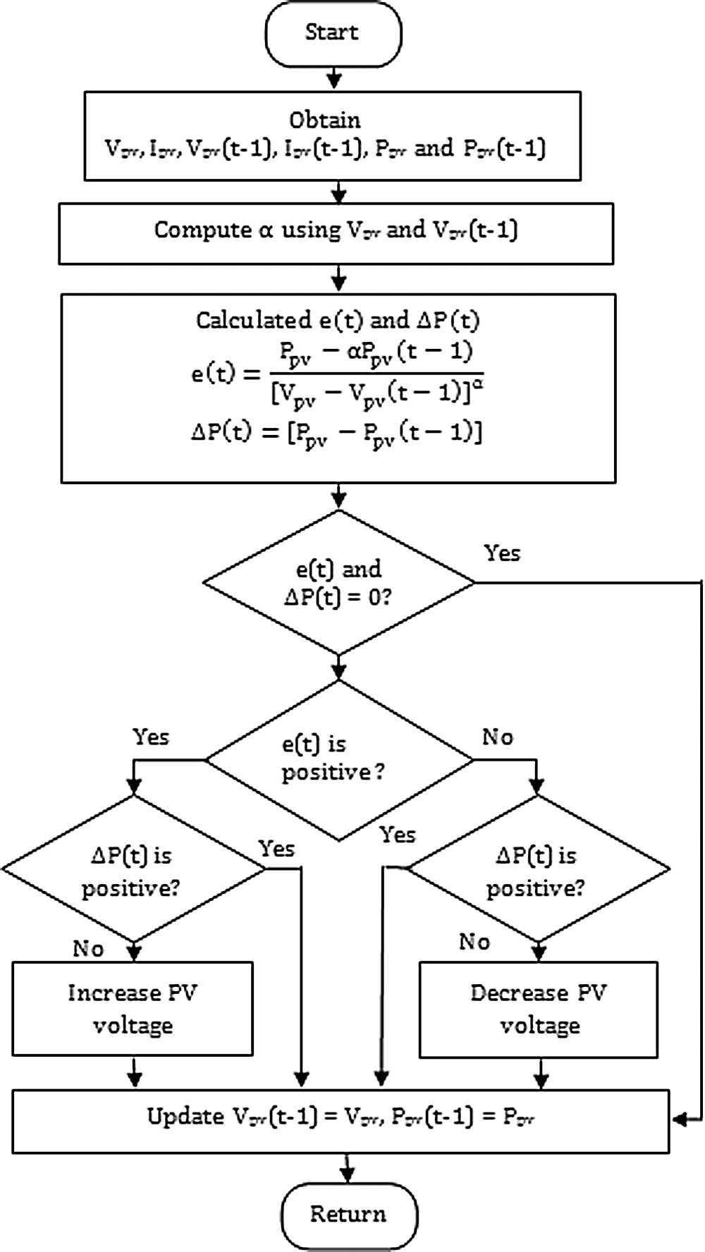
Figure 10: FFVINC-based MPPT control method flow chart
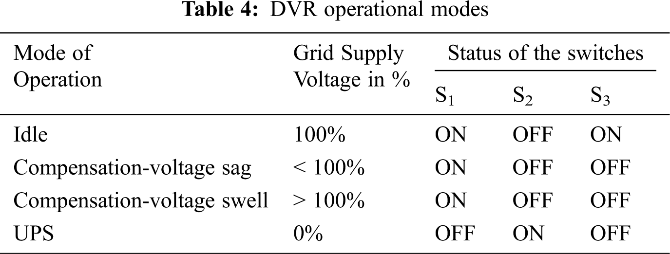
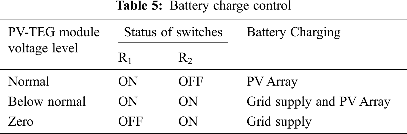
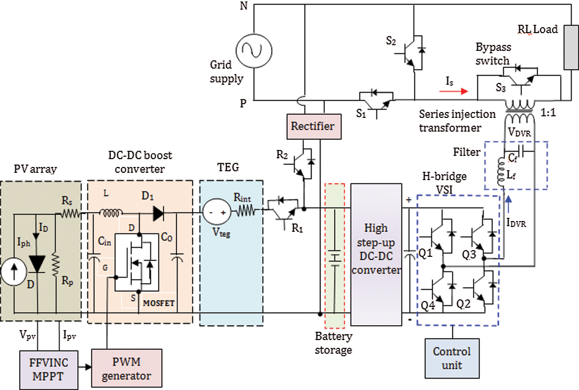
Figure 11: The overall system configuration of the hybrid PV-TEG integrated DVR
5.1.1 Voltage Compensation Mode
When the DVR identifies any voltage disturbances in the distribution system, the compensating voltage will be injected at the utility side using the series injection transformer with the desired phase angle, magnitude, and wave shape. In this mode, the switch S3 and switch S2 are OFF, and the DVR will start to compensate voltage sag/swell. The switch S1 is ON to provide the continuous supply to the load, now the voltage across the load is the sum of the voltage of the utility grid supply plus the compensation voltage supplied from the DVR system.
In ideal mode, the grid supply is at the normal level and DVR is made idle, the DC supply is blocked by turning OFF the upper and lower switches of the inverter legs. The switch S3 is ON to short circuit the secondary winding of the injection transformer and make VDVR = 0, the switch S1 ON and switch S2 is OFF to allow the utility grid to supply the required power for the load. The PV-TEG module voltage is at normal then it will charge the battery otherwise the battery will be connected to the grid supply by closing the switch R2 for charging.
5.1.3 Energy Conservation Mode
The proposed DVR system can also support saving power consumption from the utility grid by the consumer in the case of the hybrid PV-TEG module produces sufficient output power to meet out the load requirement. In this energy conservation mode, the utility grid supply will be disconnected, therefore the series injection transformer and the load will be in parallel such that to transfer the power from the PV-TEG module to the load via battery storage. In order to perform this operation, the switch R1 is ON and switch R2 is OFF. By activating this mode, the power utilization from the gridline can be minimized thereby the electricity tariff to the consumer will be reduced.
5.2 The Proposed FFVINC MPPT Control Algorithm Implementation
The proposed MPPT algorithm is developed to achieve the MPP of the PV quickly and accurately. The FLC is chosen to implement the MPPT algorithm, the control strategy is developed to use a larger tracking step size when the PV operating point is not nearer to the peak level in the P-V curve. Alternatively, the step size will be made smaller when the operating point of the PV module is closer to the peak level in the P-V curve. The dynamic variable incremental conduction is achieved by modifying the fuzzy input variable e(t) using the variable factor β. Based on error e(t) the present position of the PV operating point is identified, which is summarized as
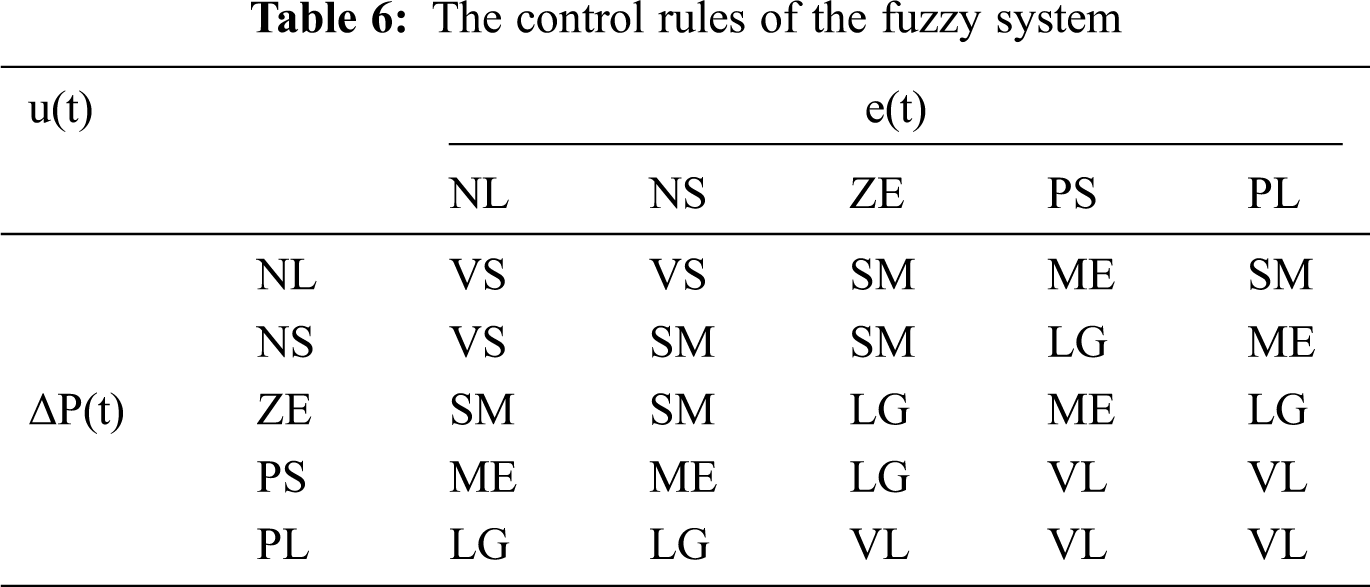
Also, the fuzzy input signal ΔP(t) confirms the movement of the PV array operating point, the positive ΔP(t) confirms that the PV array operating point is moving towards the maximum level in the P-V curve, otherwise, the negative ΔP(t) indicates that the PV operating point is moving away from the maximum level in the P-V curve. To develop the fuzzy control rules, the range of input and output parameters are split into five fuzzy sets and each fuzzy set is represented with a specific linguistic term. The linguistic terms used for the inputs are PL: Positive Large, PS: Positive Small, ZE: Zero, NS: Negative Small, NL: Negative Large. Also, the output linguistic terms are VL: Very Large, LG: Large, ME: Medium, SM: Small, VS: Very Small. The triangular shape fuzzy sets are chosen for the fuzzy variables as shown in Fig. 12. The rule-base of the FLC is designed to achieve the MPP within a short period and keep the stable output around the MPP. Suppose the error e(t) is negative (i.e., NL or NS) then the output u(t) essentially be small in magnitude to attain the MPP by decreasing the PV array voltage. If error e(t) is positive (i.e., PL or PS) then the output u(t) essentially to be maximum to attain the MPP by increasing the PV array voltage. Similarly, 25 fuzzy control rules are developed which are illustrated in Tab. 6.
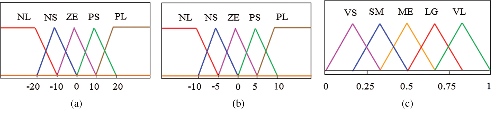
Figure 12: Fuzzy sets for the inputs and output (a) input e(t) (b) input ΔP(t) (c) output u(t).
6 Simulation Results and Discussion
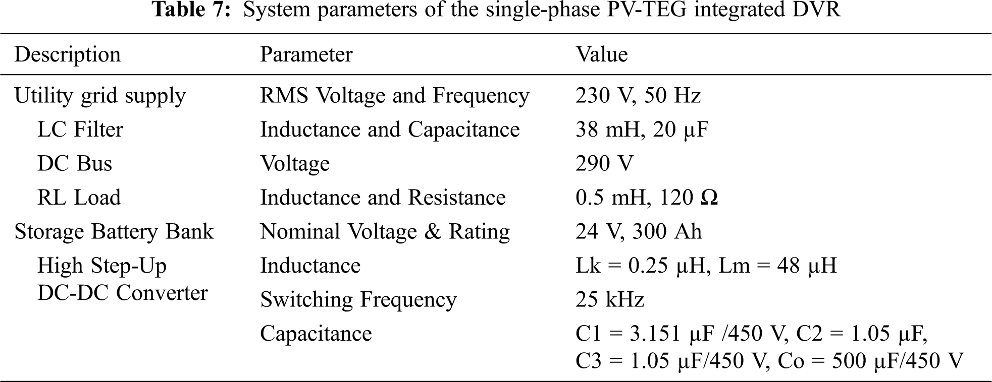
The performance of the VSI-based DVR system is investigated for the single-phase distribution system under different operating modes using MATLAB software. The simulation study parameters used for the present module are shown in Tab. 7. The investigation is carried out by considering the PV array temperature and irradiation level of 313 K and 1000 W/m2 respectively and the temperature difference between cold and hot sides of the TEG as 20 K. Based on the DVR operational modes, the analysis and discussion are carried out with four different cases. In the initial part of the investigation, the suitability of the hybrid PV-TEG energy source for the DVR operation is verified, the power output of the hybrid energy source under changing solar irradiation is tested as shown in Fig. 13(a). The study is made with an assumed PV cell temperature of 313 K and the TEG input temperature difference of 20 K, the result confirmed that the PV-TEG energy source can provide sufficient power for the DVR power quality compensation under changing solar irradiation. From Fig. 13(a), it is observed that the PV-TEG hybrid energy module will provide a quick and stable maximum power output for the different solar irradiation.
Similarly, the energy conversion efficiency of the hybrid PV-TEG study module is also verified by comparing the theoretically calculated efficiency of the standalone PV array. The efficiency of the PV array is calculated based on its output power and the area of the PV panel absorbing solar irradiation [48], it is given as
where AP denotes the area of PV panel in m2 and G denotes solar irradiation in W/m2. Similarly, the efficiency of the hybrid PV-TEG module can be determined based on the following expression.
where Pteg denotes the output power of the TEG in watts. The efficiency comparison depicted in Fig. 13(b) clearly shows that the hybrid PV-TEG study module efficiency is better than the standalone PV array which confirms that the PV array performance is increased due to the inclusion of the TEG to reduce the PV panel temperature and generating the additional power from the waste heat energy.
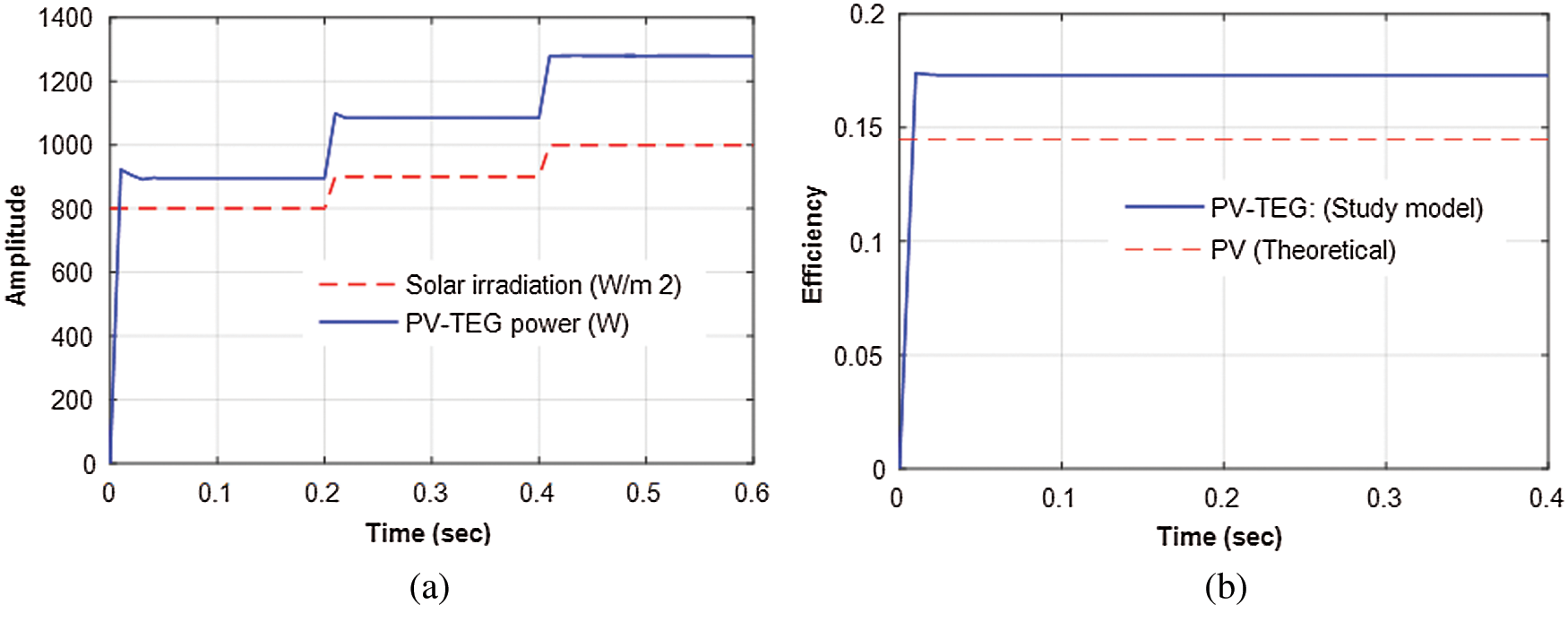
Figure 13: The hybrid PV-TEG energy module performance (a) power output against step-change in solar irradiation (b) energy module efficiency
In voltage sag compensation, the hybrid PV-TEG integrated DVR performance for the voltage drop (sag) of 20% (46 V) and 50% (115 V) at the utility grid side is studied and system response is illustrated in Fig. 14. Fig. 14(a) shows the utility grid voltage amplitude during the voltage sag, the normal grid supply voltage of 230 V comes across the voltage sags of 20% and 50% at 0.2 s and 0.4 s respectively. The DVR system immediately responds to these voltage sags and injects the required voltage in the distribution system at the load side using series injecting transformer. The injected voltage from the DVR is shown in Fig. 14(b). The voltage level across the single-phase sensitive load during the voltage sags is depicted in Fig. 14(c), this result clearly demonstrates that the voltage level across the load is unaffected due to voltage sags of grid supply. Thus, the proposed DVR system can be able to manage the voltage sag effectively and prevent the sensitive loads from the voltage disturbances for its smooth operation.
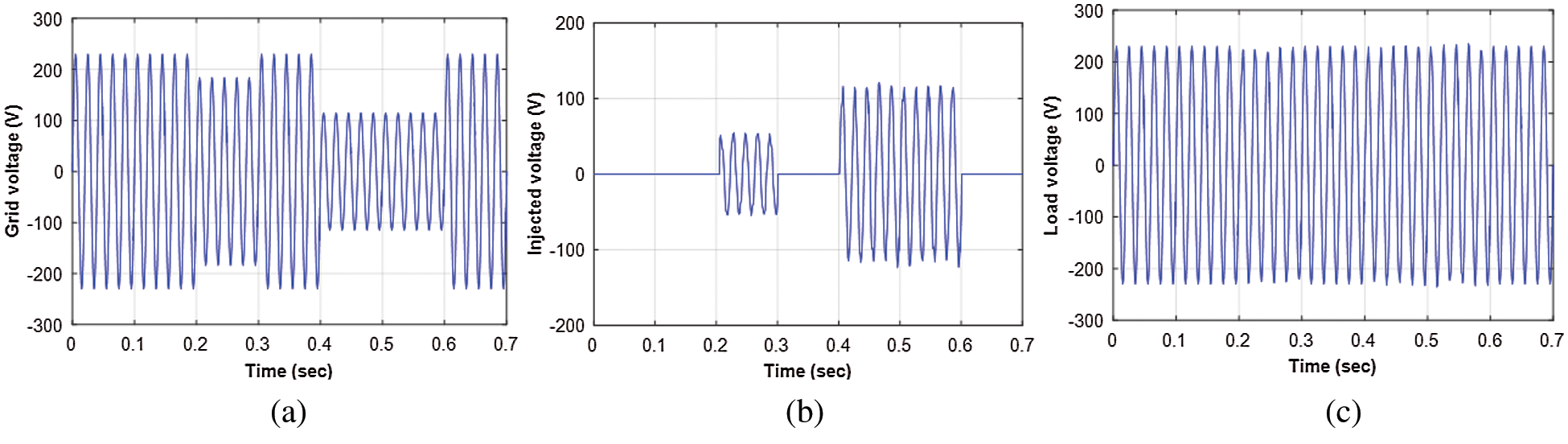
Figure 14: The DVR system performance for the voltage sag (a) grid voltage (b) DVR injected voltage (c) voltage across the load
The power flow during the voltage sag condition is also verified as shown in Figs. 15(a) and 15(b). From Fig. 15(a), when the utility supply is at normal (230 V), the chosen load of the present study model consumes a real power of 220 W from the distribution system, at 0.2 s for the 20% voltage sag the real power supplied from the utility grid to the load is reduced to 176 W. Similarly, during the 50% voltage sag the utility grid real power supply to the load is about 110 W. The DVR promptly identifies these shortages of real power to the load during the voltage sag period and inject the required real power immediately so that the load power is restored around 220 W as shown in Fig. 15(a). The power output from the hybrid PV-TEG module during this study period is also shown in Fig. 15(b). Since the hybrid energy module is operating with an efficient FLC-based FFVINC type MPPT algorithm the power output of the PV-TEG is almost constant during voltage sag periods. The reactive power supplied from the utility grid and the DVR during the voltage sag is also examined as shown in Fig. 15(b), in the present study model the load is consuming a very small amount of reactive power of 0.3 volt-ampere reactive (VAR). The reactive power supplied to the load during the voltage sag periods is also maintained at a constant level because the DVR is compensating the required reactive power.
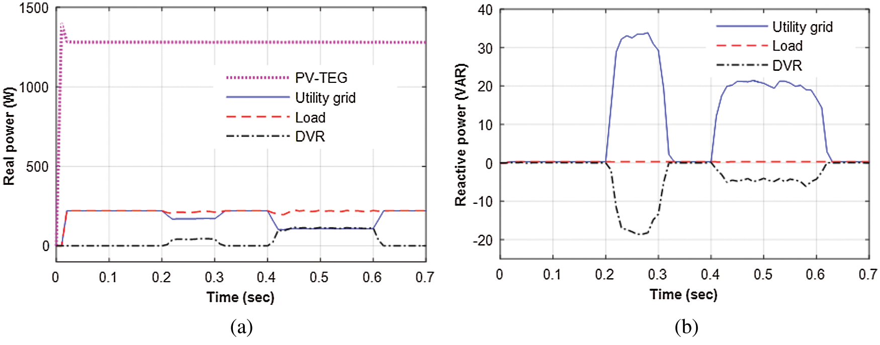
Figure 15: The DVR system power outputs during volage sag (a) real power (b) reactive power
6.2 Voltage Swell Compensation
The performance of the DVR is analyzed for the voltage swell of 15%, the voltage swell is taking place from 0.2 s to 0.3 s the actual voltage supplied from the utility grid is increased from its normal level of 230 V to 264.5 V with a phase jump of 0° as depicted in Fig. 16(a). To compensate for the voltage swell, the DVR injects the voltage of about 36.5 V in series with the grid supply voltage with 180° phase shift as depicted in Fig. 16(b). As a result, the load voltage is almost maintained at a normal level of 230 V during the voltage swell period which is depicted in Fig. 16(c). The real and reactive power measured from the source, load and DVR for case 2 is illustrated in Figs. 17(a) and 17(b). The real power supplied from the utility grid during the voltage swell period is increased as shown in Fig. 17, to compensate for the increase in real power the DVR injects a negative power from the PV-TEG module hence, the real power at the load side is maintained at the same level. The power produced by hybrid PV-TEG sources during the normal grid voltage as well as the voltage swell period is constant as illustrated in Fig. 17(a). The source and DVR reactive power flow during the voltage swell period is also depicted in Fig. 17(b) the load side reactive power is maintained at a constant level during the voltage swell period.
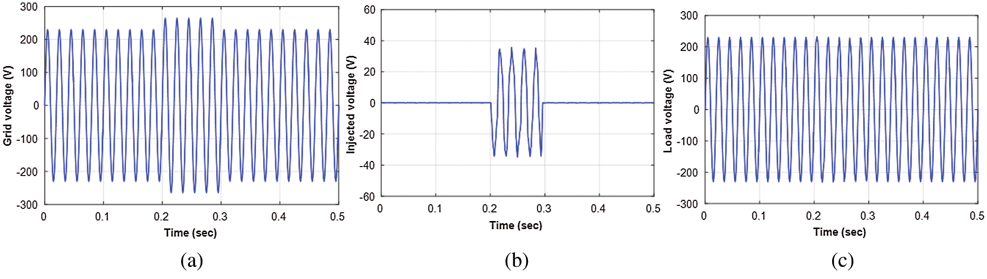
Figure 16: The DVR system performance during the voltage swell (a) grid voltage (b) DVR injected voltage (c) voltage across the load
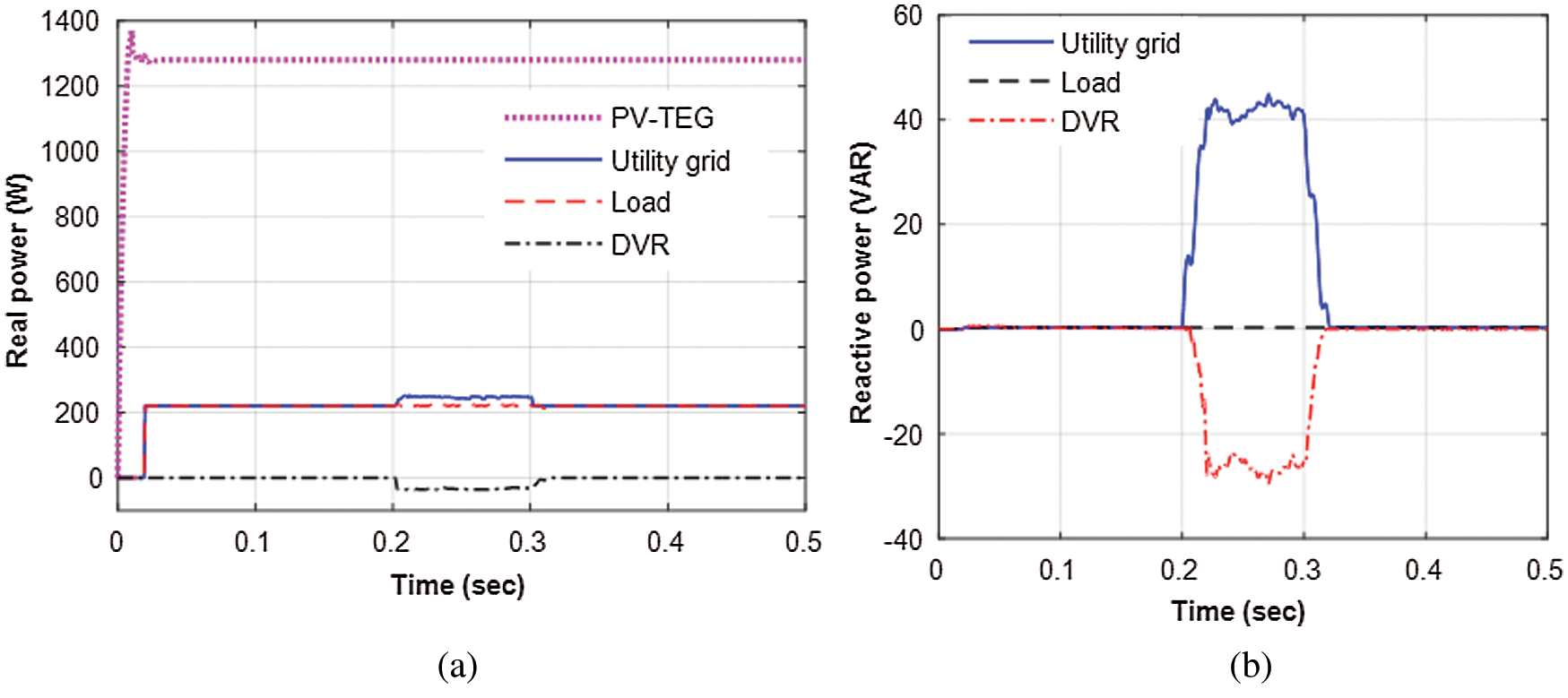
Figure 17: The DVR system power outputs during voltage swell (a) real power (b) reactive power
In outage compensation, the failure in grid supply voltage will be compensated suitably by the DVR to provide the continuous supply to the sensitive load for the uninterruptable operation. The DVR will supply the full voltage of 230 V to the load with the help of the hybrid PV-TEG module power output and the energy stored in the battery. To examine the outage compensation, the grid supply voltage is made into 0 V from 0.2 s to 0.4 s as shown in Fig. 18(a), the DVR system promptly identifies the failure in the grid supply voltage and immediately provides the required voltage to the load using the series injecting transformer. The injected voltage from the DVR during the outage is depicted in Fig. 18(b). Therefore, the load voltage during the outage period is maintained without any variation as illustrated in Fig. 18(c). Further, it is noticed that the voltage across the load is exactly sinusoidal without much distortion. Thus, the proposed DVR can manage the outage even for a long period by supplying a stable voltage to the sensitive loads. The real and reactive power supplied from the DVR during the outage compensation is shown in Figs. 19(a) and 19(b). From Fig. 19(a), the DVR is supplying about 220 W of the real power to the load during the outage period. The power output from the PV-TEG hybrid energy sources shown in Fig. 19(a) obviously indicates that the proposed MPPT algorithm can be able to extract the maximum power continuously and maintain the same output during the outage compensation period. The reactive power flow from the DVR during the outage compensation is depicted in Fig. 19(b). From the inspection of the results, it is confirmed that the DVR can inject sufficient power to the load and manage the outage effectively.
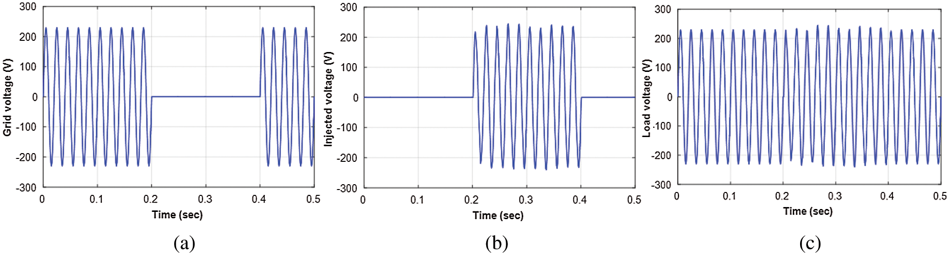
Figure 18: The DVR system performance during the outage (a) grid voltage (b) DVR injected voltage (c) voltage across the load
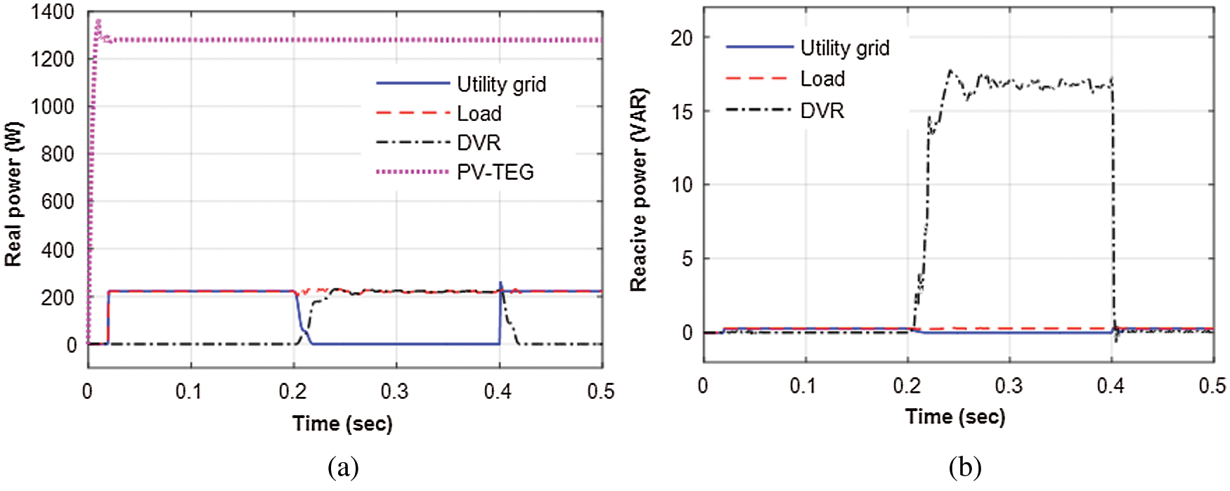
Figure 19: The DVR system power outputs during the outage (a) real power (b) reactive power
When the hybrid PV-TEG module generates sufficient or more than the load power demand, the energy conservation mode will be activated by making the utility grid supply voltage as 0 V concurrently the DVR operation is changed into the compensation mode. Therefore, the DVR will provide the total power directly to the load using the PV-TEG module output and the energy stored in the battery by which the power consumption from the utility grid is saved. The energy conservation mode operation is studied by making the grid supply voltage as 0 V, the grid supply voltage, injected voltage and load voltage of the proposed hybrid PV-TEG integrated DVR is shown in Figs. 20(a)–20(c) respectively. The study results confirmed that the DVR can provide the required voltage continuously to the load directly from the hybrid energy sources through the battery bank.
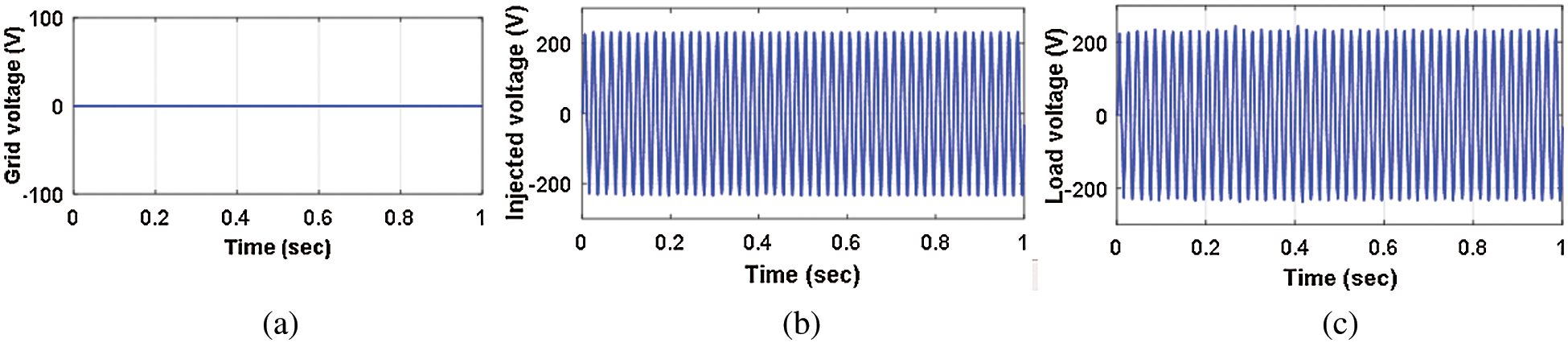
Figure 20: The DVR system performance during the energy conservation (a) grid voltage (b) DVR injected voltage (c) voltage across the load
The real and reactive power distribution during the energy conservation mode is illustrated in Figs. 21(a) and 21(b), it is noticed that the load is getting sufficient power from the hybrid PV-TEG module and the utilization of the grid power can be saved by choosing this mode of operation. The power output of the hybrid PV-TEG module under this mode is verified as shown in Fig. 22, it is confirmed that the PV combined TEG energy module can supply the maximum power to the DVR using the FLC-based MPPT algorithm. Therefore, the energy conservation mode of the hybrid PV-TEG integrated DVR system is useful to conserve electricity.
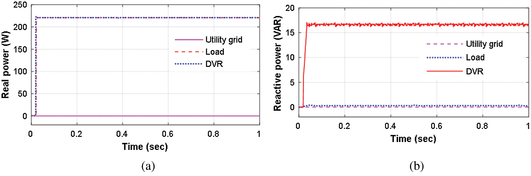
Figure 21: The DVR power during the energy conservation (a) real power (b) reactive power
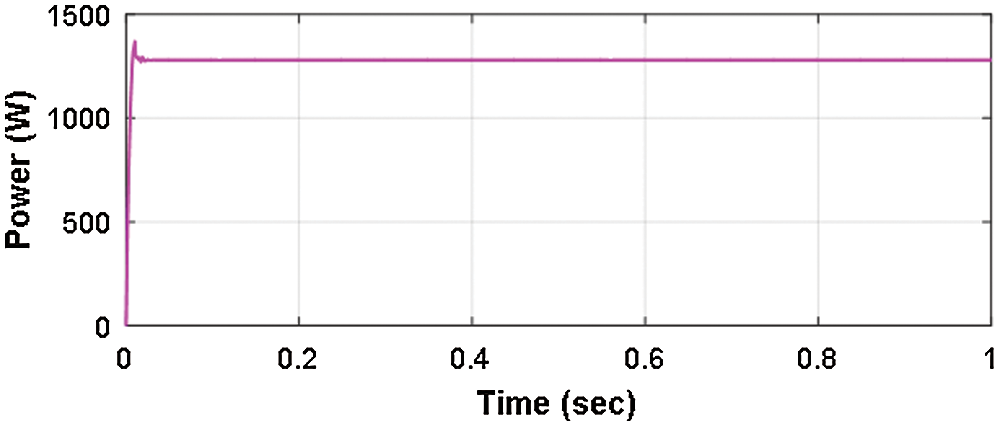
Figure 22: The hybrid PV-TEG energy module output power during the energy conservation mode
A new configuration of the H-bridge VSI-based DVR system integrated with a hybrid PV-TEG energy source has been proposed for the single-phase sensitive load power quality disturbances compensation. The hybrid renewable energy source was integrated with DVR to improve the system ability for the deep and long-term voltage disturbances compensation and energy conservation for the consumer. In the simplified H-bridge VSI circuit, the in-phase voltage compensation method was employed to maintain the supply power quality of the sensitive loads to prevent malfunctions and trouble-free operation. The FFVINC MPPT control algorithm has effectively tracked the MPP of the PV array to extract the maximum power in terms of fast and accuracy, the proposed hybrid energy module by combining the TEG with the PV array gives better power conversion efficiency which is essential for the DVR during the voltage sag/swell and outage compensation. The overall performance of the developed single-phase DVR system has been tested for voltage compensation and utility grid energy conservation. The study results were proved that the PV-TEG integrated DVR configuration can be able to maintain the sensitive load supply power quality for smooth operation. The results of outage compensation mode have confirmed that the DVR system could provide uninterruptable supply for the consumer loads using the hybrid energy module suitably to prevent the system malfunctions. Moreover, the investigation results of the energy conservation mode demonstrated that the PV combined TEG hybrid module can be able to provide adequate real and reactive powers for the DVR system thereby the electricity tariff for the consumer could be reduced.
Funding Statement: The author(s) received no specific funding for this study.
Conflicts of Interest: The authors declare that they have no conflicts of interest to report regarding the present study.
1. T. Jimichi, H. Fujita and H. Akagi, “Design experimentation of a dynamic voltage restorer capable of significantly reducing an energy-storage element,” IEEE Transactions on Industry Applications, vol. 44, no. 3, pp. 817–825, 2008. [Google Scholar]
2. V. Khadkikar and A. Chandra, “A novel structure for three-phase four-wire distribution system utilizing unified power quality conditioner (UPQC),” IEEE Transactions on Industry Applications, vol. 45, no. 5, pp. 1897–1902, 2009. [Google Scholar]
3. C. Kumar and M. K. Mishra, “Predictive voltage control of transformerless dynamic voltage restorer,” IEEE Transactions on Industrial Electronics, vol. 62, no. 5, pp. 2693–2697, 2015. [Google Scholar]
4. D. V. Tien, R. Gono and Z. Leonowicz, “A multifunctional dynamic voltage restorer for power quality improvement,” Energies, vol. 11, pp. 1351, 2018. [Google Scholar]
5. C. Y. Tang, Y. T. Chen and Y. M. Chen, “PV power system with multi-mode operation and low voltage ride-through capability,” IEEE Transactions on Industrial Electronics, vol. 62, no. 12, pp. 7524–7533, 2015. [Google Scholar]
6. A. Javadi, A. Hamadi, L. Woodward and K. A. Haddad, “Experimental investigation on a hybrid series active power compensator to improve power quality of typical households,” IEEE Transactions on Industrial Electronics, vol. 63, no. 8, pp. 4849–4859, 2016. [Google Scholar]
7. M. Rauf, A. V. Sant, V. Khadkikar and H. H. Zeineldin, “A novel ten-switch topology for unified power quality conditioner,” IEEE Transactions on Power Electronics, vol. 31, no. 10, pp. 6937–6946, 2016. [Google Scholar]
8. L. Xiong, F. Zhuo, F. Wang, X. Liu, M. Zhu et al., “A quantitative evaluation and comparison of harmonic elimination algorithms based on moving average filter and delayed signal cancellation in phase synchronization applications,” Journal of Power Electronics, vol. 16, no. 2, pp. 717–730, 2016. [Google Scholar]
9. IEEE Recommended Practices and Recommendations for Harmonics Control in Electric Power Systems, IEEE Std. 519, 1993. [Google Scholar]
10. M. Ramasamy and S. Thangavel, “Experimental verification of PV based Dynamic Voltage Restorer (PV-DVR) with significant energy conservation,” International Journal of Electrical Power and Energy Systems, vol. 49, pp. 296–307, 2013. [Google Scholar]
11. M. Nabipour, N. M. Razaz, S. G. H. Seifossadat and S. S. Mortazavi, “A novel adaptive fuzzy membership function tuning algorithm for robust control of a PV-based Dynamic Voltage Restorer (DVR),” Engineering Applications of Artificial Intelligence, vol. 53, pp. 155–175, 2016. [Google Scholar]
12. S. Hossein, M. Ghassem and A. Ali, “A new approach to improve PV power injection in LV electrical systems using DVR,” IEEE Systems Journal, vol. 12, no. 4, pp. 3324–3333, 2017. [Google Scholar]
13. G. Akhil, “THD reduction with reactive power compensation for fuzzy logic DVR based solar PV grid connected system,” International Journal of Sustainable Energy, vol. 33, no. 4, pp. 921–936, 2014. [Google Scholar]
14. R. A. Walling, R. Saint, R. C. Dugan, J. Burke and L. A. Kojovic, “Summary of distributed resources impact on power delivery systems,” IEEE Transactions on Power Delivery, vol. 23, no. 3, pp. 1636–1644, 2008. [Google Scholar]
15. M. J. J. Negroni, D. Biel and F. Guinjoan, “Energy-balance modeling and discrete control for single-phase grid-connected PV central inverters,” IEEE Transactions on Industrial Electronics, vol. 55, no. 7, pp. 2734–2743, 2008. [Google Scholar]
16. T. Shimizu, O. Hashimoto and G. Kimura, “A novel high-performance utility-interactive photovoltaic inverter system,” IEEE Transactions on Power Electronics, vol. 18, no. 2, pp. 704–711, 2003. [Google Scholar]
17. S. B. Kjaer, J. K. Pedersen and F. Blaabjerg, “A review of single-phase grid-connected inverters for photovoltaic modules,” IEEE Transactions on Industry Applications, vol. 41, no. 5, pp. 1292–1306, 2005. [Google Scholar]
18. C. Babu and P. Ponnambalam, “The theoretical performance evaluation of hybrid PV-TEG system,” Energy Conversion and Management, vol. 173, pp. 450–460, 2018. [Google Scholar]
19. F. Attivissimo, A. Di Nisio, A. M. L. Lanzolla and M. Paul, “Feasibility of a photovoltaic thermoelectric generator: Performance analysis and simulation results,” IEEE Transactions on Instrumentation and Measurement, vol. 64, no. 5, pp. 1158–1169, 2015. [Google Scholar]
20. V. Verma, A. Kane and B. Singh, “Complementary performance enhancement of PV energy system through thermoelectric generation,” Renewable & Sustainable Energy Reviews, vol. 58, pp. 1017–1026, 2016. [Google Scholar]
21. V. V. Tyagi, N. A. A. Rahim, N. A. Rahim and J. A. L. Selvaraj, “Progress in solar PV technology: Research and achievement,” Renewable & Sustainable Energy Reviews, vol. 20, pp. 443–461, 2013. [Google Scholar]
22. B. Parida, S. Iniyan and R. Goic, “A review of solar photovoltaic technologies,” Renewable & Sustainable Energy Reviews, vol. 15, pp. 1625–1636, 2011. [Google Scholar]
23. S. Ahmet, I. Kehinde, Y. Bekir and S. Abdullah, “A review on the performance of photovoltaic/thermoelectric hybrid generators,” International Journal of Energy Research, vol. 44, no. 5, pp. 3365–3394, 2020. [Google Scholar]
24. B. Singh, P. Jayaprakash and D. P. Kothari, “Adaline-based control of capacitor supported DVR for distribution systems,” Journal of Power Electronics, vol. 9, no. 3, pp. 386–395, 2009. [Google Scholar]
25. A. Ghosh and A. Joshi, “A new algorithm for the generation of reference voltages of a DVR using the method of instantaneous symmetrical components,” IEEE Power Engineering Review, vol. 22, no. 1, pp. 63–65, 2002. [Google Scholar]
26. F. Shahnia, R. Majumder, A. Ghosh, G. Ledwich and F. Zare, “Voltage unbalance analysis in residential low voltage distribution networks with rooftop PVs,” Electric Power Systems Research, vol. 81, no. 9, pp. 1805–1814, 2011. [Google Scholar]
27. N. Kanagaraj, M. Ramasamy, H. Rezk and T. Manesh, “Modified bidirectional DC-DC Boost converter fed three-phase four-wire PV-DVR,” Journal of Testing and Evaluation, vol. 48, no. 4, pp. 3087–3115, 2020. [Google Scholar]
28. S. J. Lee, H. Kim, S. K. Sul and F. Blaabjerg, “A novel control algorithm for static series compensators by use of PQR instantaneous power theory,” IEEE Transactions on Power Electronics, vol. 19, no. 3, pp. 814–827, 2004. [Google Scholar]
29. M. I. Marei, E. F. El-Saadany and M. M. A. Salama, “A new approach to control DVR based on symmetrical components estimation,” IEEE Transactions on Power Delivery, vol. 22, no. 4, pp. 2017–2024, 2007. [Google Scholar]
30. J. W. Liu, S. S. Choi and S. Chen, “Design of step dynamic voltage regulator for power quality enhancement,” IEEE Transactions on Power Delivery, vol. 18, no. 4, pp. 1403–1409, 2003. [Google Scholar]
31. A. K. Jindal, A. Ghosh and A. Joshi, “Critical load bus voltage control using DVR under system frequency variation,” Electric Power Systems Research, vol. 78, no. 2, pp. 255–263, 2008. [Google Scholar]
32. K. H. Chua, Y. S. Lim, P. Taylor, S. Morris and J. Wong, “Energy storage system for mitigating voltage unbalance on low-voltage networks with photovoltaic systems,” IEEE Transactions on Power Delivery, vol. 27, no. 4, pp. 1783–1790, 2012. [Google Scholar]
33. K. Perera, D. Salomonsson, A. Atputharajah and S. Alahakoon, “Automated control technique for a single phase dynamic voltage restorer,” in Proc. of the Int. Conf. on Information and Automation, Colombo, Srilanka, pp. 63–68, 2006. [Google Scholar]
34. J. G. Nielsen and F. Blaabjerg, “A detailed comparison of system topologies for dynamic voltage restorers,” IEEE Transactions on Industry Applications, vol. 41, no. 5, pp. 1272–1280, 2005. [Google Scholar]
35. P. Jayaprakash, B. Singh, D. P. Kothari, A. Chandra and K. Al-Haddad, “Control of reduced-rating dynamic voltage restorer with a battery energy storage system,” IEEE Transactions on Industry Applications, vol. 50, no. 2, pp. 1295–1303, 2014. [Google Scholar]
36. K. Chandan, “Predictive voltage control of transformerless dynamic voltage restorer,” IEEE Transactions on Industrial Electronics, vol. 62, no. 5, pp. 2693–2697, 2015. [Google Scholar]
37. K. Hasan, “Time-varying and constant switching frequency-based sliding-mode control methods for transformerless DVR employing half-bridge VSI,” IEEE Transactions on Industrial Electronics, vol. 64, no. 4, pp. 2570–2579, 2017. [Google Scholar]
38. M. H. Rashid, Power Electronics Circuits, Devices and Applications. New Delhi, India: Prentice-Hall of India Private Ltd., 2003. [Google Scholar]
39. M. Vilathgamuwa, A. A. D. R. Perera and S. S. Choi, “Voltage sag compensation with energy optimized Dynamic voltage restorer,” IEEE Transactions on Power Delivery, vol. 18, no. 3, pp. 928–936, 2003. [Google Scholar]
40. C. Zhan, V. K. Ramachandaramurthy, A. Arulampalam, C. Fitzer, S. Kromlidis et al., “Dynamic voltage restorer based on voltage-space-vector PWM control,” IEEE Transactions on Industry Applications, vol. 37, no. 6, pp. 1855–1863, 2001. [Google Scholar]
41. Y. P. Hsieh, J. F. Chen, T. J. Liang and L. S. Yang, “Novel high set-up DC-DC converter for distributed generation system,” IEEE Transactions on Industrial Electronics, vol. 60, no. 4, pp. 1473–1482, 2013. [Google Scholar]
42. M. Makhlouf, F. Messai and H. Benalla, “Modeling and simulation of grid-connected hybrid photovoltaic/battery distributed generation system,” Canadian Journal on Electrical and Electronics Engineering, vol. 3, no. 1, pp. 1–10, 2012. [Google Scholar]
43. I. Laird and D. Lu, “High step-up DC/DC topology and MPPT algorithm for use with a thermoelectric generator,” IEEE Transactions Power Electronics, vol. 28, pp. 3147–3157, 2012. [Google Scholar]
44. N. Kanagaraj, H. Rezk and M. R. Gomaa Behiri, “A variable fractional order fuzzy logic control based MPPT technique for improving energy conversion efficiency of thermoelectric power generator,” Energies, vol. 13, pp. 4531, 2020. [Google Scholar]
45. S. Tang, Y. Sun, Y. Chen, Y. Zhao, Y. Yang et al., “An enhanced MPPT method combining fractional-order and fuzzy logic control,” IEEE Journal of Photovoltaics, vol. 7, pp. 640–650, 2017. [Google Scholar]
46. N. Kanagaraj, “Design and performance evaluation of fuzzy variable fractional-order [PI]λDμ controller for a class of first-order delay-time systems,” Studies in Informatics and Control, vol. 28, no. 4, pp. 443–452, 2019. [Google Scholar]
47. C. H. Lin, C. H. Huang, Y. C. Du and J. L. Chen, “Maximum photovoltaic power tracking for the PV array using the fractional-order incremental conductance method,” Applied Energy, vol. 88, pp. 4840–4847, 2011. [Google Scholar]
48. A. Rezania, D. Sera and L. A. Rosendahl, “Coupled thermal model of photovoltaic-thermoelectric hybrid panel for sample cities in Europe,” Renewable Energy, vol. 99, pp. 127–135, 2016. [Google Scholar]
 | This work is licensed under a Creative Commons Attribution 4.0 International License, which permits unrestricted use, distribution, and reproduction in any medium, provided the original work is properly cited. |