DOI:10.32604/csse.2021.016430
| Computer Systems Science & Engineering DOI:10.32604/csse.2021.016430 | |
| Article |
An Efficient Medium Access Control Mechanism for Flying Ad-hoc Networks
1Department of Electronic Engineering, ISRA University, Islamabad, 44000, Pakistan
2Department of Computer Science and Information Systems, Islamic University of Madinah, Madinah, 400411, Saudi Arabia
3Hamdard Institute of Engineering & Technology, Islamabad, 44000, Pakistan
4Department of Electrical Engineering, Namal Institute, Mianwali, 42200, Pakistan
5Department of Electrical Engineering, National University of Sciences and Technology (NUST), Islamabad, 44000, Pakistan
*Corresponding Author: Muhammad Asghar Khan. Email: khayyam2302@gmail.com
Received: 02 January 2021; Accepted: 17 February 2021
Abstract: The Flying Ad-hoc Networks (FANETs) is characterized by the transition from a single large Unmanned Aerial Vehicle (UAV) to multiple small UAVs connected in an ad-hoc fashion. Since high mobility is the core feature of such networks, they are prone to route breaks within the links. The issue of connectivity loss can be coped with, to some extent, by making use of omnidirectional antennas. Such modification, however, curtails Quality-of-Service (QoS) requirements of networks in terms of bandwidth, media access delay, coverage and others. Alternately, directional antennas have advantages over omnidirectional antennas such as improved transmission range, spatial reuse and high throughput. Nevertheless, its introduction raises location-dependent issues to the Medium Access Control (MAC) protocol. This calls for an efficient MAC protocol that can cater to new directional antenna models and, at the same time, can counter the constraints associated with the dynamic UAVs. Therefore, in this article, we consider a UAV interconnection mechanism that lets the UAVs execute the communication tasks using the directional MAC protocol. The technique is advantageous as compared to the approach of utilizing the MAC protocol using omnidirectional antennas. The scheme is being implemented as a case study for Industry 4.0 inventory and traceability applications in the warehouse. For modeling and simulation purposes, we use the Optimized Network Engineering Tool (OPNET) and aim to seek an evaluation with respect to throughput, media access delay, retransmission attempts and data dropped. The results obtained demonstrate the effectiveness of the proposed scheme.
Keywords: FANETs; QoS; Industry 4.0; IEEE 802.11; MAC; OPNET; mobility models; directional antenna
Flying Ad-hoc Networks (FANETs) involves a decentralized communication network that emerges due to cooperation and collaboration between a group of small UAVs [1]. Although a FANET system is characterized by an ad-hoc mechanism, some of its features distinguish it from its predecessors, such as MANETs and VANETs. For example, the nodes in a FANET system have a higher mobility than those in VANETs and MANETs. The nodes, in addition, can either be static, particularly in the relaying network nodes, or dynamic, capable of high-speed flight for search and rescue operations [2]. Further, the nodes have ample freedom of movement and are agile enough to move and rotate in the three-dimensional (3D) space. These distinctive attributes, on the one hand, make FANETs an acceptable option for time-limit and mission-critical tasks. However, on the other hand, it inherits challenges in terms of limited on-board energy, restricted computing capability, insufficient bandwidth and others. Further, slow response time and a deteriorated performance is the immediate aftermath of bidding to carry out computationally intensive tasks.
The popular wireless technology i.e., Wi-Fi (IEEE 802.11) can be used for independent deployment of the FANET system. Wi-Fi not only provides wireless networking in the immediate vicinity but is also used because of spectrum-free bands to provide off-the-shelf, lightweight, and cost-effective communication links [3]. For example, in the following two cases, they are a good choice: first, in the event that the available communication infrastructure has been destroyed due to any reason; and secondly, in areas where complexities do not include easy access to installation and deployment. Moreover, by ensuring reliable contact between UAVs, they can speed up rescue operations. Furthermore, because of the low altitude of UAVs, this technology contributes to major performance improvements. Additionally, performance can be further enhanced with the UAV mobility model at the MAC layer with the jointly designed adaptive communications scheme.
The IEEE 802.11 MAC protocol is modified solely for omnidirectional antennas that can function in every direction. However, with an omnidirectional antenna, network coverage, delay, and throughput etc. will remain limited. In comparison, directional antennas deliver several advantages over omnidirectional antennas, such as greater coverage, spatial reuse and high bandwidth, due to the concentration of total RF energy in one direction. Nonetheless, these advantages pose some unique challenges for the MAC layer. The primary challenge with the directional antenna is the error in location estimation for high-speed UAVs [4,5]. For this reason, the combination of multiple navigation systems is the central requirement for the practical solution of error reduction in the UAVs position estimation. In FANETs, each connected UAV must be fitted with a GPS-based Inertial Measurement Unit (IMU), so that other UAVs can be placed accurately at any time. IMU can be rated by GPS signal and therefore, can provide position and angle at a faster rate [6,7].
To achieve high throughput, low latency, and fewer retransmission attempts, etc., designing an efficient MAC protocol for FANETs is very important. The primary objectives of such MAC protocols are to resolve transmission collisions of data packets, provide reduced channel access delay, and allow multiple UAVs to share a common medium fairly. In the high mobility and dynamic topology, the MAC layer in FANETs plays a significant role in network utilization [8,9].
The MAC protocol in this article consists of two antenna modes: directional and omnidirectional. Moreover, the performance is evaluated under 3D terrain model and the factors considered include network density, coverage area and UAV speed. Some of the highlights of our research work, in this paper, can be summarized as follows:
• We propose an efficient Medium Access Control (MAC) protocol based on directional antennas. The protocol involves multiple directional antennas on a single UAV.
• The proposed scheme is modeled and implemented using Optimized Network Engineering Tool (OPNET).
• In order to obtain more realistic results, we assume a 3D terrain model, where each of the UAVs flies at various altitudes.
• We consider the Reference Point Group Mobility (RPGM) model to achieve maximum precision while simulating the proposed protocol.
• We deploy the proposed scheme on to Industry 4.0 inventory and traceability applications in the warehouse as a case study.
• To justify potency of the proposed scheme as compared to the counterpart utilizing omnidirectional antennas, we compared it in terms of throughput, media access delay, data dropped and retransmission attempts.
• The findings from the comparison results demonstrated superiority of the proposed scheme.
The paper is organized as follows. Section 2, discusses the related work. Section 3, elaborates key challenges associated with directional antennas. Section 4, describes the proposed directional antennas-based MAC protocol. Section 5, presents Solution to the key challenges of directional MAC protocol. Simulation environment and performance evaluation using OPNET tool are illustrated in Section 6. Section 7, explains case study. Section 8, contains simulation results and analysis. Section 9, concludes the work.
The literature leads to relatively few research results in the area of directional antennas at the MAC layer, focusing on the UAV network. Ulukan et al. [10] proposed a MAC angular protocol (AN-MAC) in 2004 to boost the performance of the network using directional beams. The proposed protocol enables stations with a location-based scheduler to identify busy sectors to avoid collisions and congestion on the network. With an increased number of antennas per node, the authors plan to verify the performance analysis of AN-MAC on various topologies. The authors have implemented an Adaptive Medium Access Control (AMAC) protocol [11], in which two directional antennas and two omnidirectional antennas are mounted on each UAV. In terms of bandwidth, range, and delay, the performance of the proposed protocol for a UAV network with directional antennas is found to be comparably better than omnidirectional antennas. However, this scheme seems impractical due to the agile motion of UAVs. Huba et al. [12], presented an aerial network in which UAVs are mounted with directional antennas. The proposed approach combines scheduling and clustering with a single algorithm in the MAC layer, providing a robust and scalable solution. In order to show the effect of the distance between the functioning UAVs and the main beam angles, Temel et al. [13] studied different flight scenarios and used directional antennas. In terms of both data rate and latency, the authors have not, however, focused on improving network performance.
The efficiency of existing routing protocols using FANET directional antennas is researched by Biomo et al. [14]. In terms of packet delivery ratio (PDR) and latency, the proposed mechanism for this scheme results in better network performance. The authors further explored the possibility that a larger coverage of the same number of nodes is given by the directional antenna. Nevertheless, the authors used only one stream in 2D sight. Khan et al. [15] suggested a directional antenna-based medium access control (MAC) protocol in 2019, using multiple directional antennas on a single UAV in a FANET system. The suggested framework is designed and implemented in the OPNET. There has been significant progress in terms of end-to-end delay, throughput and retransmission attempt using directionally-based MAC. However, all six antennas were active in the entire period without any on/off mechanism in the proposed scheme. In 2020, the authors introduced a dual-channel MAC protocol for underwater acoustic sensor networks based on a directional antenna [16]. The switching time between the omnidirectional directional and directional antenna modes was overlooked, however, and it cannot be ignored in real-world scenarios. Finally, in 2021, Khan et al. [17] proposed a dual-mode MAC protocol for UAV-enabled ITS. The proposed scheme uses a switched-beam directional antenna with N = 4 separate antenna beams using IEEE 802.11p standard. We extended the same work by incorporating two extra beams i.e., N = 6 separate antenna beams while using IEEE 802.11g standard.
3 Key Challenges of Directional MAC Protocol
Using the MAC protocol with a directional antenna approach reduces the issues of limited bandwidth and latency, but it presents some exclusive challenges particularly at the MAC layer. These challenges include hidden terminal and exposed terminal problems, the head-of-line blocking and deafness problems, which are detailed as follows:
This particular problem results when UAVs try to start data transmission with the receiver at the same time without knowing the on-going transmission [18]. For these cases, the collision of packets occurs at the source as shown in Fig. 1. UAV A and UAV C both fall within the UAV B range. On the other side, UAV C and UAV A cannot “see” each other and should be disguised UAVs. In this case, the packet collision occurs when UAV C and UAV A unknowingly begin transmitting packets simultaneously to UAV B. Data loss occurs because of this particular problem.

Figure 1: Hidden terminal problem
The problem arises when two simultaneous transmissions between UAVs are not possible [19]. UAV B wishes to forward packets to UAV A while UAV C wished to communicate with UAV D simultaneously as shown in Fig. 2. Technically it does not seem like a concern because UAV A and D only receive one signal at a time. However, the issue occurs when the UAV B detects a UAV C signal and waits for the medium to be idle before the packet is sent. With the exposed terminal problem, network performance reduces.

Figure 2: Exposed terminal problem
3.3 Head-of-Line (HOL) Blocking Problem
Prioritized “FIFO” queues to transfer packets to the channel cause HOL problems [20]. This effect comes about because the channel is free in one direction and busy in the other. If a packet is blocked at the top of the queue, it stops transmitting packets although its direction is available for transmission. Find the condition outlined in Fig. 3 where UAV A interacts with UAVs B, D and E. If there are packets of UAVs B, D, and E in the queue of UAV A and they assume sequential transmission. Let us suppose that UAV B and C are linked together in the transmission of data. At the same time, UAV A must wait until and unless UAVs B and C complete the transmission of their data. In such a situation UAV A can plan packets for UAV E and UAV D instead of waiting for UAV B, which causes the HOL problem.

Figure 3: HOL blocking problem
A UAV that uses directional antennas in FANETs is generally considered “deaf” to all other UAVs except for the one that beams in that direction [21]. The deaf problem arises when one UAV tries to connect continuously with another UAV which focuses on another UAV on different antenna beams. Each failed attempt doubles the back-off interval, and thus reduces network performance. Consider Fig. 4, where node A is considered “deaf” to node A, if node A wants to connect to node B but is configured to node C by the beam. The deafness problem affects network efficiency in resolving delay and unequal allocation of network resources [22].

Figure 4: Deafness problem
4 Proposed Directional Antennas Based MAC Protocol
The directional antenna option in the OPNET simulator is not available on any node by default. Therefore, we must build our own directional antenna, which requires users to use the antenna pattern editor to determine the representation of antenna patterns. Using a node editor antenna module to give the gain specified by the pattern, the antenna pattern can be connected with a radio transmitter and/or receiver. We implemented the standard 802.11g DCF MAC for designing the proposed protocol. The 802.11g protocol operates in the 2.4 GHz ISM band and is an 802.11b superset, offering fast data speeds between 11 Mbps and 54 Mbps. This protocol uses CMSA/CA, an important technique in the WLAN MAC layer with Distributed Coordination Function (DCF). As FANETs performance decreases with a variety of factors such as high speed, 3D movement, regular distance changes between UAVs and contact quality fluctuations. Thus, the distance between linked UAVs in the proposed scheme will not reach the transmission limit of the directional antenna. Medium access table is set up with the help of RTS/CTS messages to know the destination location information as well as adjacent UAV’s.
The UAV station model is planned such that each UAV has six directional antennas covering an area of 360o. The proposed model also has external GPS and IMU installed to map and update the location and distance of the neighboring UAV. To book medium-to-exchange packages, the standard 802.11g uses RTS/CTS packets. We presume a 3D terrain model, in order to produce more accurate results, each UAV will fly at various heights. Each UAV is equipped with an altimeter pod (consisting of radar, lidar, and others) to achieve the desired effects, maintaining its height relative to the terrain it flies to. Therefore, it is clear that UAV connectivity would be influenced by the geographical features of the regions. More information on the proposed MAC directional protocol can be found below.
The proposed scheme uses a switched-beam directional antenna with N = 6 separate antenna beams. All six beams can cover an area of 3600 in total, as shown in Fig. 5. The beam width of each antenna is 60o. Thus, to design the proposed mechanism as shown in Fig. 6, six separate RF modules with a single MAC chip are required. We used Friis equation in the proposed system to get parameters for the antenna.
In the above Eq. (2), P represents power, and G denotes gain; respectively, subscript t and r stand for transmitted and received. In addition, λ is the wavelength, and R is determining the range of transmission.
For omnidirectional antennas, setting the parameters in the OPNET simulator as follows will provide the transmission of 1000 meters.: Pr = −95 dBm, Pt = −195 dBm, Frequency = 2.4 GHz and Gr = Gt = 0 dB.
In the case of 6-beam directional antenna, with the same transmission range i.e., 2449 m, we will have Pr = −95 dBm, Pt = −195 dBm, Frequency = 2.4 GHz and Gr = Gt = 7.8 dB.

Figure 5: Beams configuration for directional antennas

Figure 6: Single MAC chip integrated with directional antennas beams
In a directional antenna, some power is still radiating in the side lobes, although most of the power is directed towards the central beam. This power is considered an interference among the remaining UAVs. The interference zone between directional antennas is illustrated in Fig. 7. The maximum transmission range of the main lobe beam Rm, side lobe beam Rs and guard zone Rg.
Pt, Pr and Gs are the transmitted power, received power and side lobe gain respectively as mentioned in Eq. (4).

Figure 7: The maximum transmission ranges of DIZ and IIZ zones
UAVs in the Indirect Interference Zone (IIZ) will concentrate their antennas beyond beam N. The total volume of IIZ expressed in m3 is the sum of the conic zone linked to the receiver antenna and the sphere connected to the sidelobe gain of the receiver. Probability distribution function (PDF) is use for deployment of K number of UAVs with their initial locations over a terrain. The volume of the spherical zone Vc and the side lobe sphere Vs is determined from Eqs. (5) and (6). Moreover, in Eqs. (7) and (8), the total volume of IIZ, VIIZ, and the volume of DIZ, VDIZ, are determined.
The total interference (It) and SIR experienced by all the UAVs can be measured from Eqs. (9) and (10) as follow:
The maximum number of UAVs without effecting the on-going communication in the field can be expressed as in Eq. (11):
In the FANET system, due to the agile movement of the UAVs, it is important to select the required mobility model in order to achieve maximum accuracy in the simulation performance. There are also occasions where a swarm of UAVs is tasked with patrolling a certain point in a certain area. Therefore, we used Reference Point Group Mobility (RPGM) [23] for the simulation of a group of UAVs in the proposed scheme. In the RPGM model, UAVs are clustered around a centralized node, called a group head (backbone UAV in our case), to accomplish collaborative work. A reference point describes the movement of the whole group, including position, altitude, speed, and velocity. The group head follows a random viewpoint (RWP) mobility model, and most of the UAVs move using RPGM around the group head i.e backbone UAV (see Figs. 8a and 8b) [2]. There are several types of mobility models, such as columns (CLMN) [2], nomadic community (NC) [2], and purse (PRS).

Figure 8: Mobility models: (a) Nomadic community (NC) with three UAVs (b) Mobility pattern of one group (i.e., three UAVs) using RPGM
Two antenna types, namely directional and omnidirectional, constitute the proposed MAC protocol. There will be only one antenna beam operating in the directional mode for data transmission. All the other beams can be deactivated by setting each sector beam gain to –200 dB, resulting in a linear gain of 0 [24]. In the proposed scheme a gain of 7.8 dB has been set for the active beam. By contrast, all N sectors are active with a gain of 0 dB in the omnidirectional mode, resulting in a linear gain of 1. When there is no RTS-CTS-Data-ACK exchange, UAVs can stay in this mode. Initially, in the proposed scheme, each UAV with pending data sends an RTS frame in all directions using N beams. By default, a traditional CSMA/CA algorithm is used to send these RTS messages. The channel is heard omnidirectionally by all the attached UAVs that are idle or in a back off state. When the RTS packet is received by the intended UAV, all other beams with maximum power, except the one receiving the signal, are disabled. Then, through the maximum signal strength beam, the UAV in question sends a CTS packet. Likewise, the transmitting UAV also chooses the beam that receives the CTS with the maximum power. It would then transmit data in the same direction using the beam. Even, in a directional pattern, ACK packets are sent.
To accomplish the data communication under the proposed scheme, supposing UAV_A has requested to send data packets to UAV_C as illustrated in Fig. 9. Two control messages, called RTS and CTS, are initiated before the actual data transfer. Under the proposed scheme, these messages would include data transfer time, location and orientation information as well as antenna beam numbers. Initially, UAV_A transmits RTS packets in all six directions using directional antennas. When the destination UAV (i.e., UAV_C) collects the RTS packet, senses the channel up to SIFS interval before transmitting the CTS packet to the UAV_A. In the case of channel availability, it will return a CTS packet. It also regularly updates the target information table. The neighboring UAVs such as UAV_B and UAV_D will be aware of the on-going communication between UAV_A and UAV_C. The UAV A will read the address of the UAV C which marks the received maximum power beam. For a certain amount of time, UAVs other than the UAV C will deactivate all beams in that particular direction via DNAV. Similarly, the scheme also allows simultaneous communication between UAV_D and UAV_B through Spatial Division Multiple Access (SDMA) in the same infrastructure as described in Fig. 10.

Figure 9: UAV topology fitted with six directional antenna beams

Figure 10: FANETs achieve SDMA topology
Directional antenna requires information about the exact areas of communication with the UAV in order to communicate effectively. When the UAV receives a frame, it updates a targeted information table. It adds the address, frame and antenna beam of sending UAV. This is achieved on the MAC layer, wherein each GPS update the MAC protocol uses the directional antenna to provide the exact position of the neighboring UAVs.
4.6 Directional Network Allocation Vector (DNAV)
The IEEE 802.11based MAC protocol has two sensing mechanisms called physical and virtual carrier sensing. Virtual carrier sensing is done through NAV, while DNAV is used only to retain those channel that are in the direction and transmission range of other UAVs. DNAV is the directional version of NAV.
5 Solution to the Key Challenges of Directional MAC Protocol
This section is dedicated to explaining solutions to some of the unique problems associated with directional antennas.
5.1 Solution to Hidden Terminal Problem
This particular problem can be solved using the carrier sensing mechanism with the help of RTS / CTS packages in the 802.11 DCF protocol. In the proposed mechanism, RTS packets for sending UAVs and CTS packets of receiving UAVs are sent directionally. For this reason, each UAV updates a DNAV table for storing the recent information about antenna beams. DNAV is integrated with the neighboring UAV’s target information table for coordination.
5.2 Solution to Exposed Terminal Problem
Using directional NAV times (per sector) can solve this problem. Only sectors that accidentally receive RTS / CTS during neighboring transmission are blocked for transmission.
5.3 Solution to Head-of-Line (HOL) Blocking Problem
To address this issue, we modified the queuing field to reduce the pending packet flow. Depending on the details contained in the DNAV, the minimum waiting time for packet transfer is expected.
5.4 Solution to Deafness Problem
For FANETs, considering a novel control packet will reduce the problem of deafness with directional antennas. It basically lets a busy receiver for a certain period of time against the source UAV.
6 Simulation Environment and Performance Evaluation
Modeling and simulating the proposed scheme are achieved using OPNET Modeler 14.5. OPNET consists of an antenna pattern editor where an antenna directionality is modeled and an antenna gain is set. We made modifications in the MANET node model according to which the proposed MAC protocol for both directional and omnidirectional antennas can be implemented. The directional antenna node model provides all of the compulsory interfaces that are set in each antenna for working with six separate beams. In the proposed model, each UAV has 60o beam width that enables them to cover an area of 360o with the help of six directional antennas. For all beams, the UAV will sense the signal intensity and mark the beam with maximum signal strength for data communication. The UAV can also block all other beams except the one with maximum signal strength. Across all UAVs, the data rate of the proposed scheme is selected in the IEEE 802.11 g standard as 54 Mbps. For more detailed information, further parameters are summarized in Tab. 1. The performance of the proposed MAC mechanism is evaluated on the basis of throughput, media access delay, data dropped and retransmission attempts.
Table 1: Simulation parameters

7 FANETs Enabled Autonomous Industry 4.0 Warehouse
The proposed scheme is tested using a case study on autonomous Industry 4.0 warehouse involving inventory and traceability applications. The architecture of the proposed system as shown in Fig. 11. Airborne platforms (i.e., small UAVs) are equipped with an RFID reader (NPR) and Raspberry Pi to carry out the inventory task as shown in Fig. 11. In specific, active Ultra High Frequency (UHF) RFID was chosen as an item identification technology due to its success in multi-metallic obstacle environments [25]. Moreover, it can read every tag on a site including difficult locations and elevations. It is important to remember here that to perform a wide range of inventory and tracking tasks, the UAVs can be accounted for with various accessories, such as cameras, IMU, sensors, GPS systems, and others. As with the RFID tags used, they are RF-Code active UHF tags that can be read with the NPR Active Track 2 reader (e.g., Active Rugged Tag-175S). Such a reader is connected to the Raspberry Pi via an Ethernet cable. I- The Raspberry Pi’s collected tag UIDs are first stored locally in a JavaScript Object Notation (JSON) file and then sent to the ground station through Wi-Fi.

Figure 11: Implemented architecture
8 Simulation Results and Analysis
Figs. 12–15 show the performance of MAC protocol with directional versus the omnidirectional antennas for FANETs. In the graphs, the x-axis specifies simulation time and y-axis stipulates the throughput in bits, media access delay in seconds, data dropped in bits, and retransmission attempts in packets respectively. The proposed scheme is tested under the area of 5000 m × 5000 m composed of 50 UAVs. UAVs are located in five zones, each consisting of 10 UAVs. The simulation using the OPNET simulator is performed for two different scenarios i.e., MAC with directional and omnidirectional antennas respectively to emulate a group of UAVs under the RPGM mobility model. We chose the RPGM model because, under the RPGM model, the movement of UAVs is controlled by a reference point, which is the group head in a particular zone. That way, the network stays fully connected all the time. The results of the simulation authenticate that the proposed MAC-based directional antenna scheme meets the desired QoS requirements. That is, the use of directional antenna in terms of throughput, media access delay, data dropped and retransmission attempts provides better performance than that of the default MAC protocol using omnidirectional antennas. Using an omnidirectional antenna, when UAVs move away from one another, and the distance between them increases, network performance deteriorates. For this purpose, each UAV in the same Basic Service Set (BSS) assumes that other UAVs will terminate communication before transmitting frames if the MAC protocol is based on the use of an omnidirectional antenna. Each UAV that is available in the same BSS must, therefore, wait until the other UAV completes its transmission by the same protocol. In comparison, the proposed MAC protocol, which uses directional antennas, allows each UAV to concurrently use the same channel for transmitting data with other UAVs over the same BSS. Moreover, the proposed scheme would require retransmission of each UAV against any transmission that fails. They will continue to transmit until the receiving UAV sent an ACK frame or up to the maximum retransmission limit.
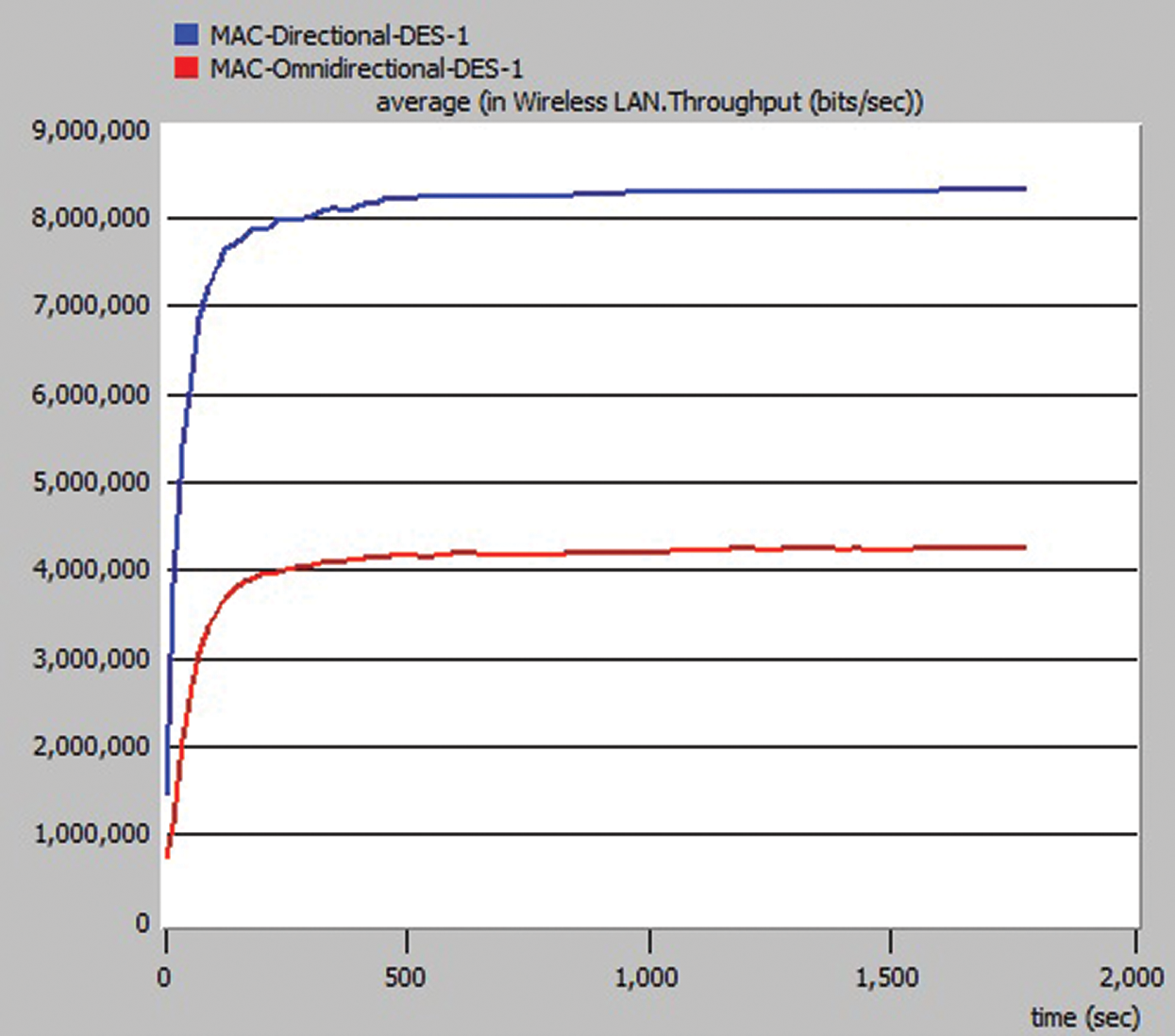
Figure 12: Throughput (in bits/sec)

Figure 13: Media access delay (in sec)
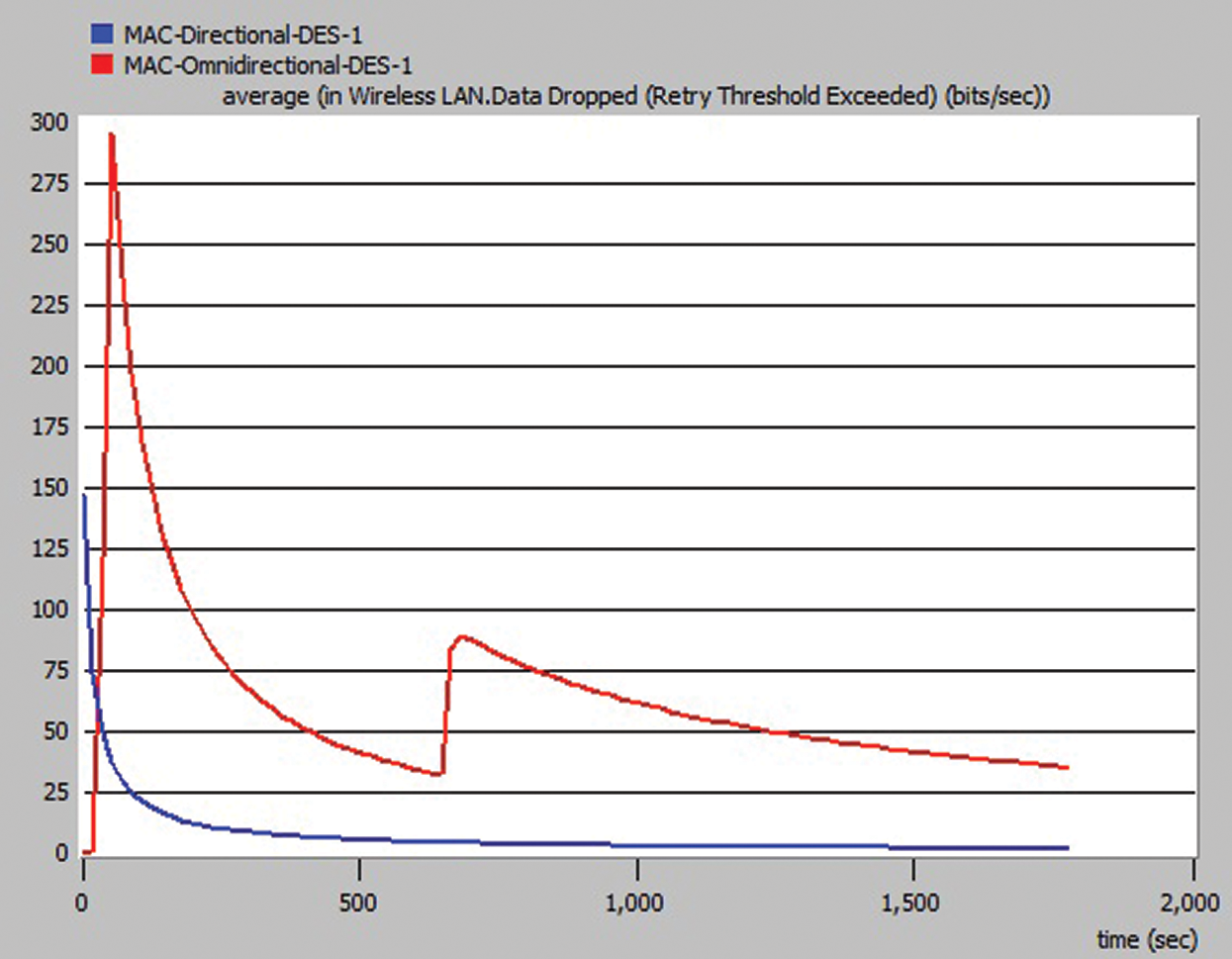
Figure 14: Data dropped (in bits/sec)

Figure 15: Retransmission attempts (in packets)
Compared to the omnidirectional antenna, the directional antennas can be used to enhance spatial reusability, network coverage and bandwidth. It can also be useful for FANETs, where there is a much greater distance between nodes than its predecessors, such as MANETs and VANETs. Therefore, in this article, a group of UAVs fitted with directional antennas has been considered. We suggested an adaptive MAC protocol for implementing the latest configuration for the directional antenna. Since the proposed MAC mechanism integrates the antenna’s directivity with CSMA and SDMA, allowing each UAV to share bandwidth simultaneously with other UAVs in the same BSS becomes fair. Moreover, the proposed scheme overcomes the unique challenges associated with a MAC protocol based on directional antennas. The simulation results using OPNET in terms of the throughput, media access delay, data dropped and retransmission attempts confirm that the proposed scheme is better than the Omni-directional antenna default MAC protocol.
Acknowledgement: The authors would like to thank the reviewers for their time and review.
Availability of Data and Materials: The data used for the findings of this study is available upon request from the corresponding authors.
Funding Statement: The authors received no specific funding for this study.
Conflicts of Interest: The authors declare that they have no conflicts of interest to report regarding the present study.
1. M. A. Khan, I. M. Qureshi, I. Ullah, S. Khan and F. Khanzada. (2020). “An efficient and provably secure certificateless blind signature scheme for flying ad-hoc network based on multi-access edge computing,” Electronics, vol. 9, no. 30, pp. 1–22. [Google Scholar]
2. A. Guillen-Perez and M. D. Cano. (2018). “Flying ad hoc networks: A new domain for network communications,” Sensors, vol. 18, no. 10, pp. 3571. [Google Scholar]
3. M. A. Khan, I. M. Qureshi and F. Khanzada. (2019). “Hybrid communication scheme for efficient and low-cost deployment of future flying ad-hoc network (FANET),” Drones, vol. 3, no. 1, pp. 16. [Google Scholar]
4. G. Choudhary, V. Sharma and I. You. (2019). “Sustainable and secure trajectories for the military Internet of drones (IoD) through an efficient medium access control (MAC) protocol,” Computers & Electrical Engineering, vol. 74, no. 4, pp. 59–73. [Google Scholar]
5. S. Vashisht, S. Jain and G. S. Aujla. (2020). “MAC protocols for unmanned aerial vehicle ecosystems: Review and challenges,” Computer Communications, vol. 160, no. 6, pp. 443–463. [Google Scholar]
6. D. Jung and P. Tsiotras. (2007). “Inertial attitude and position reference system development for a small UAV,” in Proc. 26th AIAA Aeroacoustics Conf., Rohnert Park, California, pp. 1–15. [Google Scholar]
7. G. Mao, S. Drake and Anderson. (2007). “Design of an extended kalman filter for UAV localization,” in Proc. 2007 Information, Decision and Control, Adelaide, Qld, pp. 224–229. [Google Scholar]
8. M. Y. Arafat, S. Poudel and S. Moh. (2020). “Medium access control protocols for flying ad hoc networks: A review,” IEEE Sensors Journal, vol. 21, no. 4, pp. 4097–4121. [Google Scholar]
9. W. Zafar and B. M. Khan. (2017). “A reliable, delay bounded and less complex communication protocol for multicluster FANETs,” Digital Communications and Networks, vol. 3, no. 1, pp. 30–38. [Google Scholar]
10. E. Ulukan and O. Gurbuz. (2004). “Using switched beam smart antennas in wireless ad hoc networks with angular MAC protocol,” in Proc. MEDHOCNET, Bodrum, Turkey, pp. 1–8. [Google Scholar]
11. A. I. Alshbatat and L. Dong. (2010). “Adaptive MAC protocol for UAV communication networks using directional antennas,” in Proc. ICNSC, Chicago, IL, USA, pp. 598–603. [Google Scholar]
12. W. Huba and N. Shenoy. (2012). “Airborne surveillance networks with directional antennas,” in Proc. ICNS, St. Maarten, Netherlands Antilles, pp. 1–7. [Google Scholar]
13. S. Temel and I. Bekmezci. (2014). “Scalability analysis of flying ad hoc networks (FANETsA directional antenna approach,” in Proc. BlackSeaCom, Odessa, Ukraine, pp. 185–187. [Google Scholar]
14. J. D. M. M. Biomo, T. Kunz and M. St-Hilaire. (2017). “Directional antennas in FANETs: A performance analysis of routing protocols,” in Proc. MoWNeT, Avignon, France, pp. 1–8. [Google Scholar]
15. M. A. Khan, I. M. Qureshi, I. U. Khan, A. Nasim, U. Javed et al. (2018). , “On the performance of flying ad-hoc networks (FANETs) with directional antennas,” in Proc. IMTIC, Jamshoro, Sindh, Pakistan, pp. 1–8. [Google Scholar]
16. J. Yang, G. Qiao, Q. Hu, J. Zhang and G. Du. (2020). “A dual channel medium access control (MAC) protocol for underwater acoustic sensor networks based on directional antenna,” Symmetry, vol. 12, no. 6, pp. 1–18. [Google Scholar]
17. M. A. Khan, T. A. Cheema, I. Ullah, F. Noor, S. U. Rehman et al. (2021). , “A dual-mode medium access control mechanism for UAV-enabled intelligent transportation system,” Mobile Information Systems, vol. 2021, pp. 1–16. [Google Scholar]
18. Y. B. Ko, V. Shankarkumar and N. H. Vaidya. (2000). “Medium access control protocols using directional antennas in ad hoc networks,” in Proc. INFOCOM, Texas, USA, pp. 13–21. [Google Scholar]
19. H. N. Dai, K. W. Ng, M. Li and M. Y. Wu. (2013). “An overview of using directional antennas in wireless networks,” International Journal of Communication Systems, vol. 26, no. 4, pp. 413–448. [Google Scholar]
20. V. Kolar, S. Tilak and N. B. Abu-Ghazaleh. (2004). “Avoiding head of line blocking in directional antenna,” in Proc. LCN, Zurich, Switzerland, pp. 385–392. [Google Scholar]
21. R. R. Choudhury and N. H. Vaidya. (2004). “Deafness: A MAC problem in ad hoc networks when using directional antennas,” in Proc. ICNP, Berlin, Germany, pp. 283–292. [Google Scholar]
22. H. Gossain, C. Cordeiro, D. Cavalcanti and D. Agrawal. (2004). “The deafness problems and solutions in wireless ad hoc networks using directional antennas,” in Proc. GLOBECOM, Texas, USA, pp. 108–114. [Google Scholar]
23. H. Hong, M. Gerla, G. Pei and C. C. Chiang. (1999). “A group mobility model for ad hoc wireless network,” in Proc. MSWiM, Seattle, WA, USA, pp. 53–60. [Google Scholar]
24. G. Boggia, P. Camarda, C. Cormio and L. A. Grieco. (2008). “A BIBD based MAC protocol for wireless ad hoc networks with directional antennas,” in Proc. CSNDSP, Graz, pp. 25–29. [Google Scholar]
25. T. M. Fernández-Caramés, O. Blanco-Novoa, I. Froiz-Míguez and P. Fraga-Lamas. (2019). “Towards an autonomous industry 4.0 warehouse: A UAV and blockchain-based system for inventory and traceability applications in big data-driven supply chain management,” Sensors, vol. 19, no. 10, pp. 2394. [Google Scholar]
 | This work is licensed under a Creative Commons Attribution 4.0 International License, which permits unrestricted use, distribution, and reproduction in any medium, provided the original work is properly cited. |