DOI:10.32604/csse.2021.014011
| Computer Systems Science & Engineering DOI:10.32604/csse.2021.014011 | |
| Article |
Mechanical-Hydraulic Co-Simulation of Full Hydraulic Articulated Steering System
School of Mechanical and Aerospace Engineering, Jilin University, Changchun, 130022, China
*Corresponding Author: Jinshi Chen. Email: spreading@jlu.edu.cn
Received: 30 August 2020; Accepted: 27 October 2020
Abstract: With the development and improvement of the hydraulic steering system, the articulated steering system became the research focus of numerous domestic and foreign scholars. The full hydraulic steering system with a compact structure and ease of operation, is widely used in articulated steering mode. Furthermore, its performance can directly impact the steering sensitivity and stability. This paper studies the working principle and actual structure of the priority valve and the steering control valve, which are very important. By setting up a mathematic model, the system’s load-sensing characteristics and the impact of steering control valve bypass throttle damping on steering stability can be analyzed. The Hydraulic Components Design (HCD) model was established for the hydraulic part of this system. It is proved that the model can reflect the system’s actual properties by comparing simulation and experimental results. The dynamic model is based on its actual prototype parameters by taking the tire and ground forces into account. The steering process’s dynamic characteristics are co-simulated in the 1D+3D system model by combining AMESim and Virtual.Lab Motion. The simulation results show that the system’s load-sensing characteristics ensure the sensitivity of the steering operation, and the bypass throttle damping has significantly improved the operation stability and lowered down the cylinder pressure fluctuations. This can improve the system performance by appropriate optimization.
Keywords: Articulated vehicle; full hydraulic steering system; load-sensing; steering
Nomenclature
| A1, A2, A3, A4, A5, A6, A7, A8, A9: | The area of orifice C1, C2, C3, C4, C5, C6, C7, C8, C9, mm2 |
| Q1, Q2, Q3, Q4, Q5, Q6, Q7, Q8, Q9: | The flow through the orifice C1, C2, C3, C4, C5, C6, C7, C8, C9, L·min−1 |
| PS, PCF, PEF: | Pressure of priority valve inlet port, CF port, EF port, MPa |
| PLS, PH1, PH2, PFD, PL, PR, PT: | Pressure between each orifice in steering control valve, MPa |
| PLS, PH1, PH2, PFD, PL, PR, PT: | Pressure between each orifice in steering control valve, MPa |
| ΔP: | The pressure drop of inlet orifice in steering control valve, MPa |
| k: | Spring stiffness of priority valve, N·mm−1 |
| x: | Spool displacement of priority valve, mm |
| x0: | Spring pre-compression of priority valve, mm |
| xZ: | Linear displacement difference between spool and sleeve of steering control valve, mm |
| Af: | Action area of the priority valve spool, mm2 |
| AZ: | The area of steering load equivalent orifice, mm2 |
| QL-R: | The flow through the steering load equivalent orifice, L·mm−1 |
| QZ: | The flow through steering control valve, L·mm−1 |
| Cd: | Flow coefficient |
| ρ: | Hydraulic oil density, kg·m−3 |
| ωf: | Angular velocity of the steering control valve spool, rad·s−1 |
| θm: | Angular displacement of metering motor, exactly the angular displacement of sleeve, rad |
| θf: | Angular displacement of spool, rad |
 : : | Angular velocity of the metering motor, rad·s−1 |
| Dm: | Displacement of metering motor, L·r−1 |
| d: | The diameter of the spool and sleeve engaging surface, m |
| Qm: | The average flow through the metering motor, L·min−1 |
| Tg: | The torque of metering motor, N·m |
| Tl: | Friction torque of metering motor, can be regarded as a constan, N·m |
| B: | Viscous damping, kg·s−1 |
| Ac1, Ac2: | Two active areas of the steering cylinder piston, no rod side and rod side, mm2 |
| U(t): | Speed of the steering cylinder piston, mm·s−1 |
| F: | External loads acting on the steering cylinder piston, N |
| m: | Steering cylinder piston mass, kg |
| VH: | Rod chamber volume of steering cylinder (Including pipeline), mm3 |
| E: | Effective bulk modulus of the oil, N·mm−2 |
| λC: | The leakage coefficient of the steering cylinder |
Any steering system should keep the vehicle traveling straight or change its direction flexibly following the required operation. Its performance influences the vehicle steering’s sensitivity and stability and is an important factor in ensuring safe driving and reducing driver labor intensity. The articulated steering mode is widely used as the main steering form of loaders and other vehicles due to its great flexibility and reliability [1,2].
The articulated steering mode usually uses full hydraulic steering systems because they are compact, have fewer components, and have better sensitivity and stability. A coaxial flow amplifying load-sensing full hydraulic steering system can meet the steering’s requirements in assigning flow preferentially and ensuring steering flow, regardless of the steering load. The remaining flow can be supplied to the work system, thereby eliminating the fixed displacement pump’s power loss and improving the system efficiency. Meanwhile, the above system has a coaxial flow amplification characteristic. It can play the role of flow amplification without a flow amplification valve due to its superior performance and simple structure. However, the steering wheel angular displacement θ and the steering cylinder displacement y cannot be produced simultaneously, i.e., the response time of the priority valve spool and the load-sensing oil circuit. There is always a delay in the steering operation. Also, owing to the inertia force of units connected to the steering cylinder, the cylinder rod will vibrate around the given location.
Domestic and international research shows that different hydraulic shock, swing, and other unstable situations exist in the steering process, causing instability in the start and stop steering phases. The operator can feel shaking at high and low steering speeds, affecting normal operation. Thus, research on the full hydraulic steering system is fundamental in improving articulated vehicles’ operating performance and efficiency.
Caterpillar has studied the hydraulic working and steering system with flow-sharing valve [3,4]. Sany, Liugong, Foton-Lovol and other Heavy Industry Enterprises focused on improving the flow amplification full hydraulic steering system with flow amplification valve and the load-sensing hydraulic steering system [5–7]. Eaton has done a lot of research on structural optimization of the full hydraulic steering control valve and developed one which can eliminate the entrap phenomenon [8,9]. XCMG and Jilin University have researched modeling and analysis of the full hydraulic steering stability and analyzed the tire-ground mechanics in the steering operation [10,11]. In the past, the steering system’s research was mostly focused on establishing a static and dynamic mathematical model, analyzing the system’s characteristics, and then doing a digital simulation to optimize components and system performance. However, this method was restricted to the mathematical model’s qualitative research due to ignoring some important parameters’ effects. There is a lack of appropriate study of the interaction between the tires and ground in the steering process. Therefore, the research results of steering stability have little practical significance.
Based on the steering control valve and priority valve’s actual structure, a HCD simulation model is established, and the dynamics steering load model, which is based on actual steering structures, is built in this paper. The work conducted 1D+3D mechanical-hydraulic co-simulation by combining AMESim and Virtual.Lab Motion, then analyzed the influence of the load-sensing characteristic and the impact of bypass throttle damping on steering stability.
2 The Composition and Principle of The System
The coaxial flow amplifying load-sensing full hydraulic steering system investigated in this paper is composed of a Pump 1 (fixed displacement pump in this research), Static priority valve 2, Closed center coaxial flow amplifying steering control valve 3 and Steering cylinders 4. They form a position control system and the displacement of the steering cylinder piston rod and steering wheel angular displacement have a linear relationship. The hydraulic diagram of the system is shown in Fig. 1.
As shown in Fig. 1, the priority valve is a constant-pressure-drop component and the rotary structure of the steering control valve is equivalent to a three-direction acting valve. The priority valve’s LS port is connected to the load-sensing LS port of the steering control valve. The priority valve always preferentially supplies flow to the steering system regardless of the load change and the extra flow is supplied to work systems. The metering motor of the steering control valve is connected to the sleeve by a pivot pin. When the spool rotates, hydraulic oil goes into the metering motor, promotes motor rotation and drives the sleeve. They become a servo system.
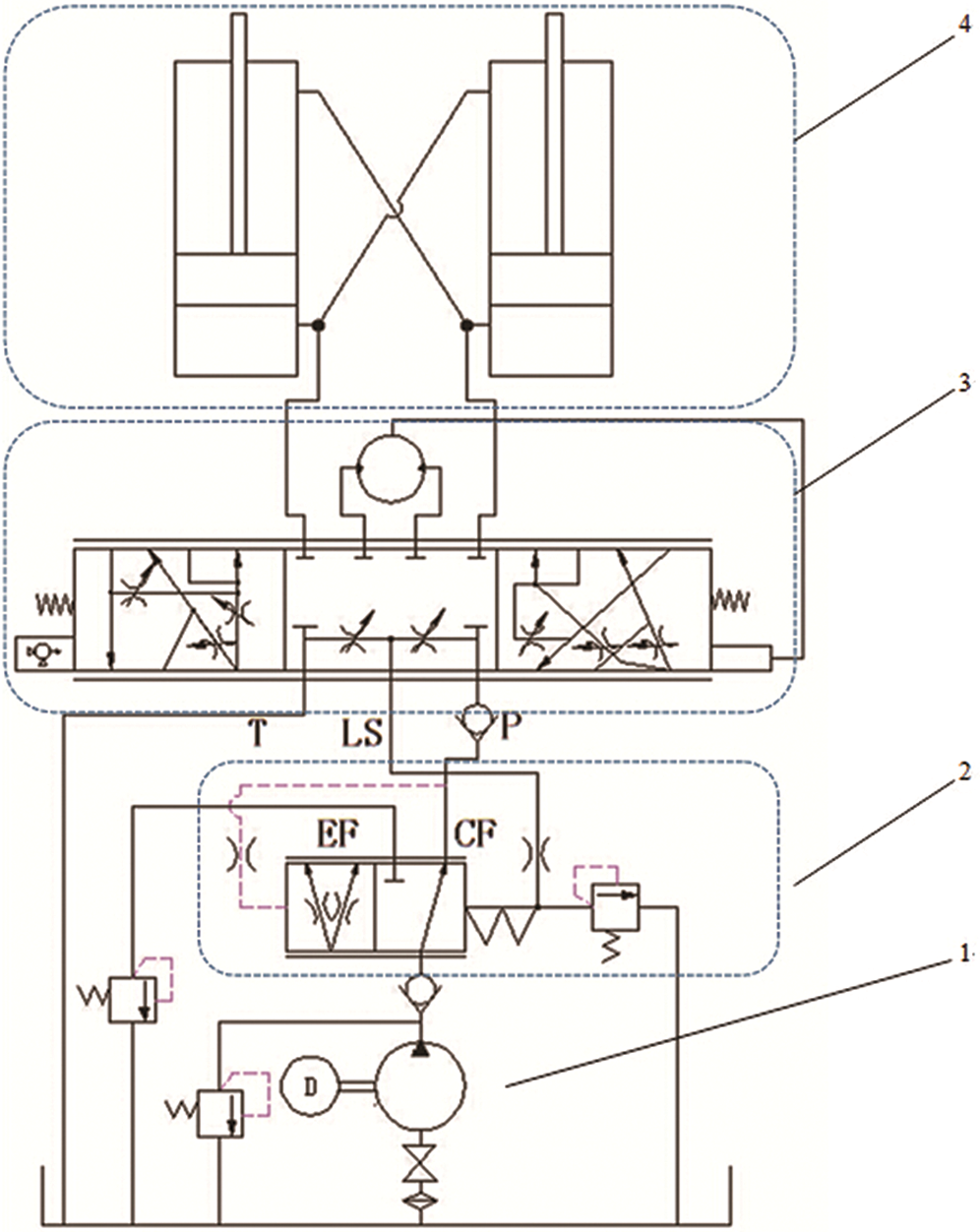
Figure 1: Hydraulic diagram of coaxial flow amplifying load-sensing full hydraulic steering system. 1- Pump; 2- Static priority valve; 3- Closed center coaxial flow amplifying steering control valve; 4- Steering cylinders
When it goes straight, the steering control valve is in its medium position, and P port is connected to neither the R nor the L port. At this time, there is no oil going into the steering cylinder. Since the CF port connects to T through the small orifice of P-LS, LS-T, the outlet pressure of the priority valve is greater than the LS port pressure. The spring chamber is in a low pressure, which will cause the spool to move left against the spring force, making the CF Orifice decrease and the EF Orifice increase. Under this condition, most oil is supplied to the work system, with only a small part being back to the tank via LS port. During the steering operation, the steering control valve’s LS port pressure feeds back to the spring chamber of the priority valve, adjusting the CF Orifice opening and steering flow. The hydraulic oil flows into steering cylinders through the metering motor, and part of the oil flows into the steering cylinder directly via the coaxial flow amplifying at the same time. Due to the constant-pressure-drop character of the priority valve, the inlet orifice of the steering control valve has a constant pressure drop. Therefore, with the increase of the steering speed, CF port flow increases as it is proportional to the open area of this orifice, which is, in turn, proportional to the steering speed.
3 Mathematical Model, Important Parameter Analysis
By studying the actual structure of important components of the steering system, priority valve and steering control valve, which are shown in Figs. 2a and 2b, a schematic diagram of important equivalent damping in this steering system has been drawn in Fig. 3:
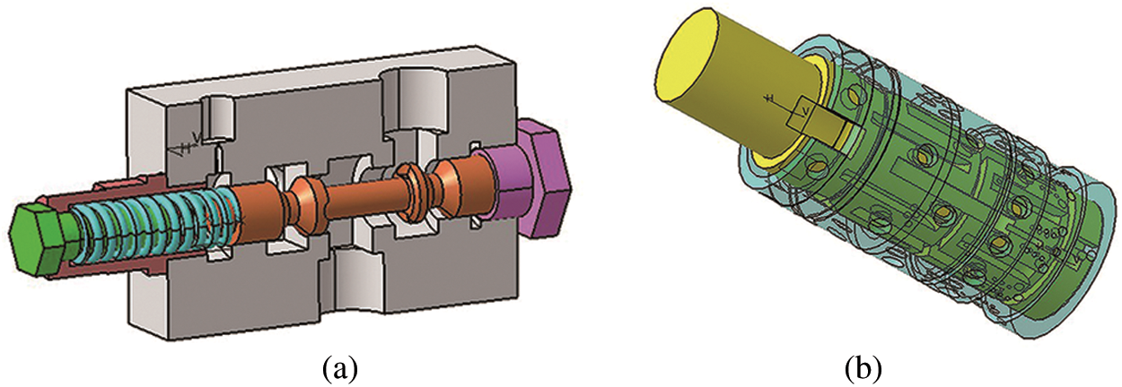
Figure 2: The structure: (a) priority valve (b) steering control valve
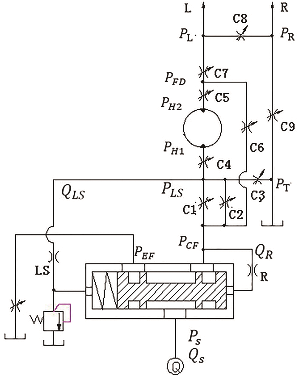
Figure 3: The schematic diagram of important equivalent damping of the steering system
3.1 Load-Sensing Characteristic of the System
According to the flow rate continuation equation and equilibrium equation of the system, the equation for the pressure drop of the inlet orifice in the steering control valve is shown in Eq. (1):

As can be seen from the above equation: the inlet orifice pressure drop is affected by the spring stiffness, active spool area, spring pre-compression, and spool displacement. Since spring stiffness, active spool area, and spring pre-compression are constant, and the spool displacement is not much relative to the spring pre-compression, the inlet orifice pressure drop is a constant value basically.
The flow of the inlet orifice is shown in Eq. (2):

An increase in steering load has several effects: PLS increases, ΔP decreases, the priority valve spool moves and CF port flow increases, leading to an increase of ΔP. So, the regulatory function of constant-pressure-drop ensures that the inlet orifice pressure drop ΔP remains constant. In this case, the steering inlet flow is only related to the open area of this orifice, which is controlled by the steering speed.
3.2 Mathematical Model of Steering Control Valve
A flow amplifying steering control valve has a cycloid metering motor, which is connected to 12 holes of rotary spool and sleeve through the 7 holes of the valve body. Excluding motor leak, the flow through the metering motor can be expressed as shown in Eq. (3):

During its rotation, the axial force of the metering motor is zero because every part of this system is fixed. The pressure in the radial is evenly distributed, which means that its radial force is in balance. Thus, the force balance equation of the metering motor is the force balance equation of the steering control valve. In the steering process, the load on the motor rotor is mainly generated by the viscous drag torque and friction torque between the rotary spool and sleeve, as well as the sleeve and the valve body. Therefore, the force balance equation of the metering motor is as shown in Eq. (4):

The viscous resistance can be neglected as it is a small value comparing to the frictional torque. The friction torque of the metering motor can be expressed as in Eq. (5):

Considering an expansion of the spool and sleeve into a planar structure according to their axis, the opening of steering control valve is their horizontal displacement difference, as shown in Eq. (6):

When there is no steering operation, a small part of the flow connects to the tank though orifice C2 and C3; while other orifices are in the state of negative opening. PLS is in a low pressure state to ensure most of the flow is supplied to the work system.
When the Steering operation starts, orifice C2 and C3 close. The oil flows into the steering control valve through orifice C1 and C6, and the flow relationship between each port of the steering control valve is as shown in Eqs. (8)–(11):

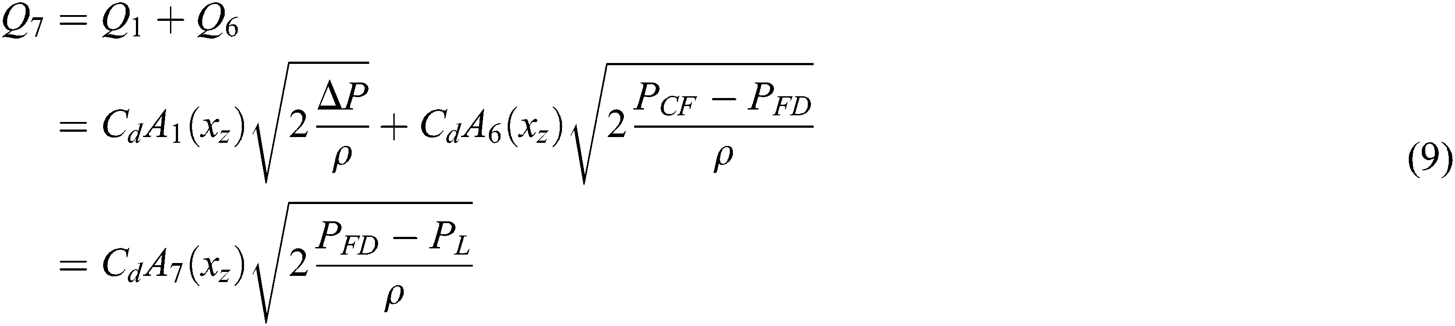
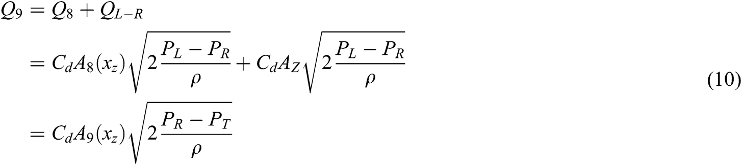
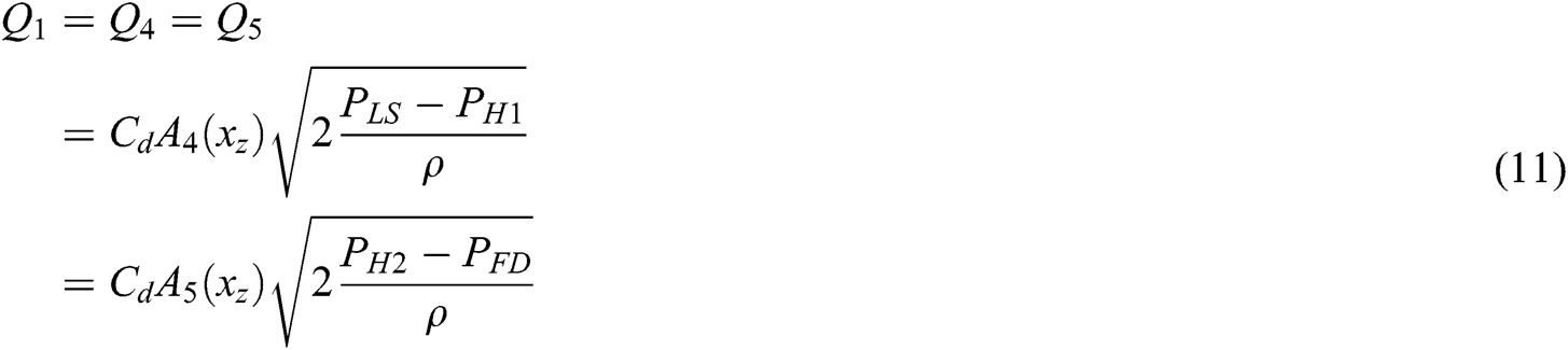
The pressure relationship can be expressed as in Eq. (12):
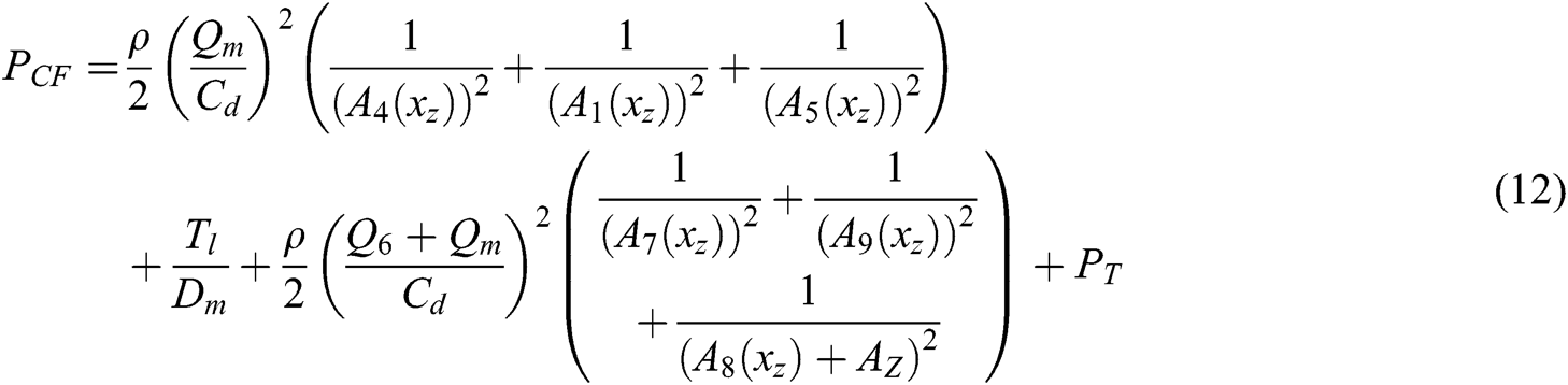
Where:

3.3 The Impact of Bypass Throttle Damping on Steering Stability
Studies have shown that the full hydraulic steering system has problems such as pressure shock and steering cylinder piston vibration, which can influence steering stability. The sudden increase of steering load creates a sudden shift in flow. It also causes instantaneous cylinder pressure rise and pressure shocks, accompanied by a huge noise and vibration, which would damage the sealing elements, affect the life of hydraulic components and systems. Orifice C8 is provided in order to absorb pressure spikes of two steering cylinder chambers in the steering process, relieve pressure oscillation and improve steering stability.
3.3.1 Research on Bypass Circuit Damping Characteristics
The study is carried out in the following two conditions [12,13].
Under no bypass throttle damping circumstances, System 1:
A schematic diagram of steering cylinder system under this condition is shown in Fig. 4:
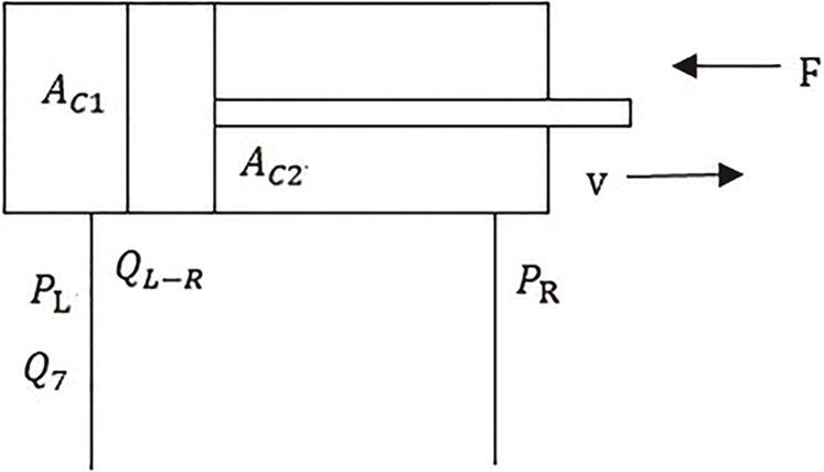
Figure 4: Schematic diagram of steering cylinder system under no bypass throttle damping C8 condition
The steering cylinder piston force balance equation and flow continuity equation of no rod chamber are shown in Eqs. (14) and (15):


The Laplace transform of the above equations are shown in Eqs. (16) and (17):


System control block diagram is shown in Fig. 5:
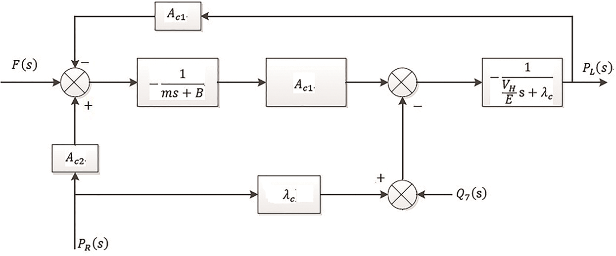
Figure 5: System control block diagram of steering cylinder system with no bypass throttle damping C8
Under the certain steering speed circumstances, hydraulic oil flow rate remains unchanged, Q7(s) = 0. If the return pressure stays unchanged, PR(s) = 0, then the transfer function can be obtained, as shown in Eq. (18). The output is the pressure of no rod chamber PL(s), and the input is the load F(s):
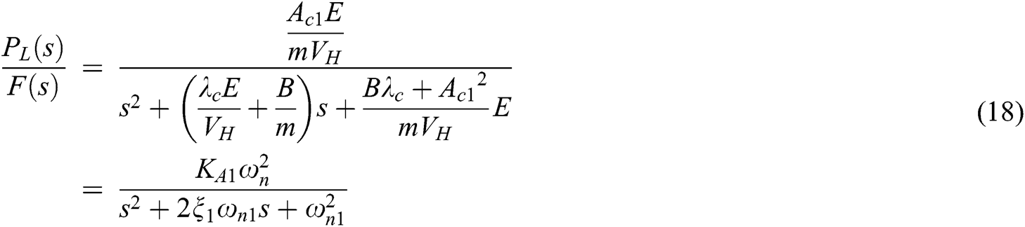
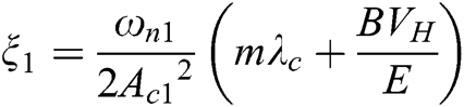
Because B and λc are tiny quantities, and Ac12>>bλc, given Bλc/Ac12 = 0, the system gain KA1, undamped natural frequency ωn1 and damping ratio ξ1 are: 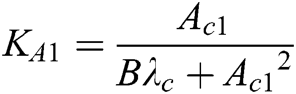 ,
, 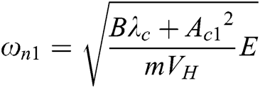 ,
, 
(b) Under the existing bypass throttle damping circumstances, System 2:
A schematic diagram of steering cylinder system under this condition is shown in Fig. 6:
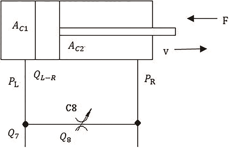
Figure 6: Schematic diagram of steering cylinder system under the existing bypass throttle damping C8 condition

Steering cylinder pressure - flow linear equation is shown as Eq. (20):

Where: 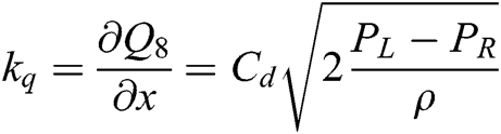 ——Flow gain of the bypass throttle;
 ——Throttle pressure - flow coefficient.
Laplace transform for Eqs. (14), (15), (19) and (20) shown as Eqs. (21)–(24):


System control block diagram as shown in Fig. 7:
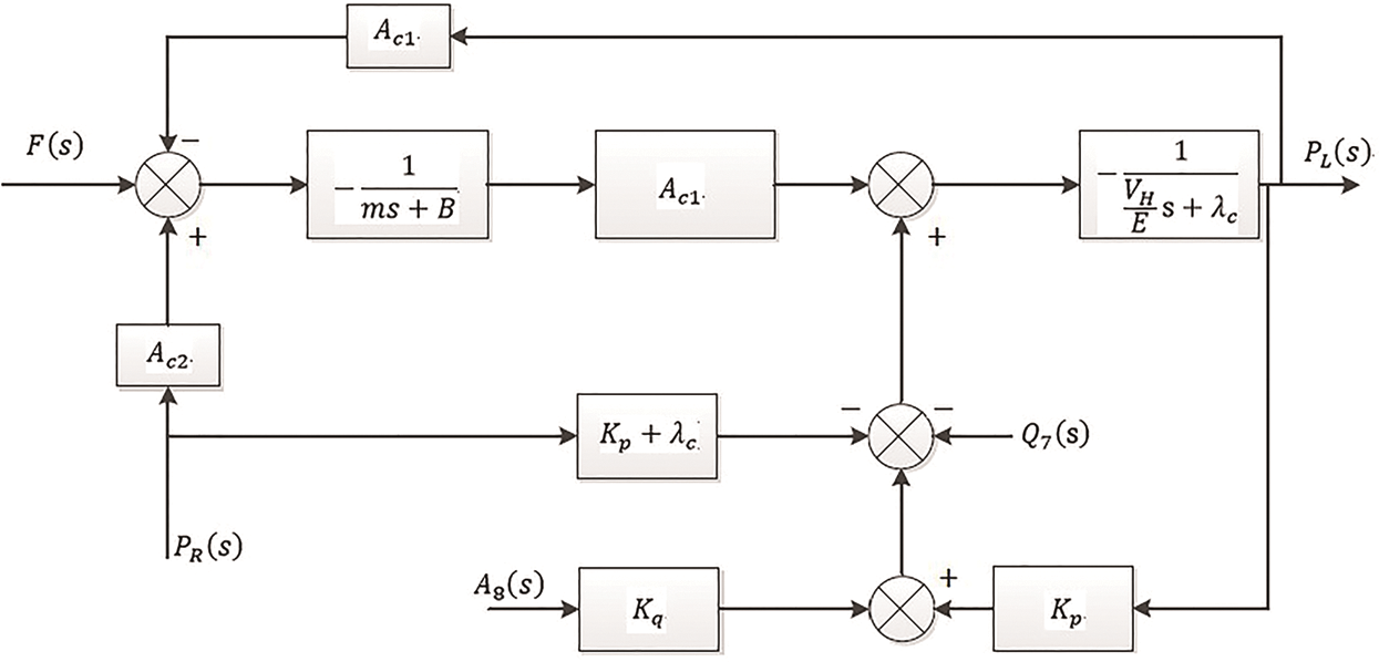
Figure 7: System control block diagram of steering cylinder system under the existing bypass throttle damping C8 condition
Under certain steering speed circumstances, hydraulic oil flow rate remains unchanged, Q7(s) = 0. If throttle opening of the bypass throttle remains unchanged, A8(s) = 0, the return pressure stays unchanged, PR(s) = 0, then the transfer function is obtained, as shown below. The output is the pressure of no rod chamber PL(s), and the input is the load F(s):
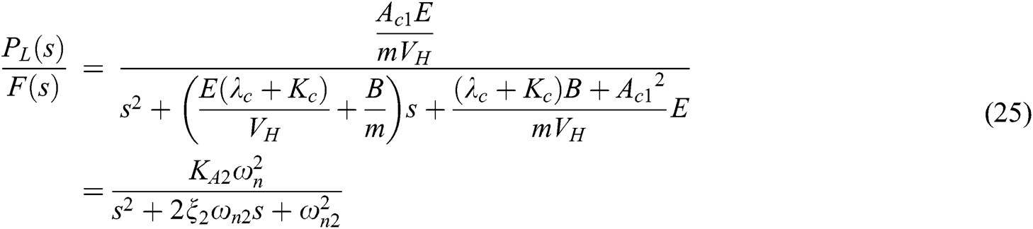
Similarly, Kc is also a tiny quantity, so given B(λc + Kc)/Ac12 = 0, the system gain KA2, undamped natural frequency ωn2 and damping ratio ξ2 are:

3.3.2 Dynamic Characteristics of Cylinder Pressure Under Step Signal Load
Depending on whether a bypass damper exists, the different characteristic equations are shown as Eqs. (26) and (27):


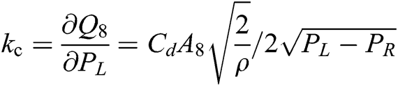
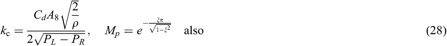
According to the Hurwitz stability criterion: if the characteristic equation coefficients are greater than 0, the system is stable. Thus, these two systems are stable. As load F increases, PL increases. As the following Eq. (28) shows, kc will decrease, ωn essentially unchanged, which causes a decrease in ξ and an increase in pressure overshoot Mp (The larger the value ξ, the smaller the value Mp). It increases the system oscillation frequency and adjustment time, and also decreases stability. Therefore, the sudden increase of steering load will cause oscillation of the system.
The severity of system oscillations is determined by the damping ratio ξ. When ξ is smaller, the oscillation processes is more serious. |ξωn| decides the speed of oscillation damping process, and when |ξωn| is bigger, the decay process is faster, and vice versa. From the above analysis, we can learn:


Therefore, in comparison with system 1, system 2 has faster attenuation and smaller overshoot of pressure shock response caused by unit step signal load.
3.3.3 The Impact of Orifice Size on the System Response Stability and Rapidity
Keeping other parameters unchanged, Kc and ξ2 will increase and the pressure overshoot Mp will decrease with increasing the throttle opening. As a result, the oscillation frequency will decrease and system stability improve accordingly. However, the size of the bypass damper C8 is limited by speed-load characteristics and position stiffness of the system.
(a) Speed-load characteristics:
The relationship between the output speed v and the load F of the actuator, v = f(F), is called the speed-load characteristics of the system. From the above analysis, the steering cylinder speed characteristic equation can be expressed as shown in Eq. (34):
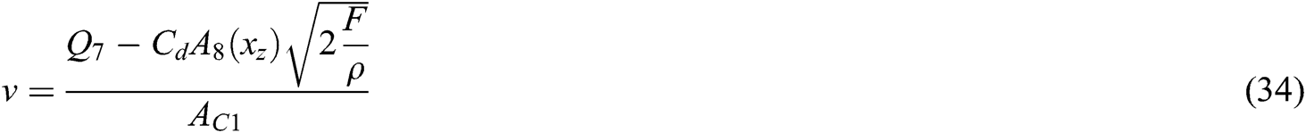
The influence of a change in the load F on the speed v is represented by the speed-load stiffness T. The larger the stiffness T, the smaller change of velocity v caused by the change of F and hence the better the speed stability of the hydraulic system.
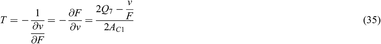
From Eq. (35), when the load F remains unchanged, the speed-load stiffness T is higher when the throttle opening area is smaller. On the contrary, T is lower when the throttle opening area is larger. To ensure the stability of the steering operation, the system requires a sufficiently high level of stiffness T.
(b) Position stiffness:
The expressions of cylinder piston displacement can be obtained from the above analysis, shown as follows:
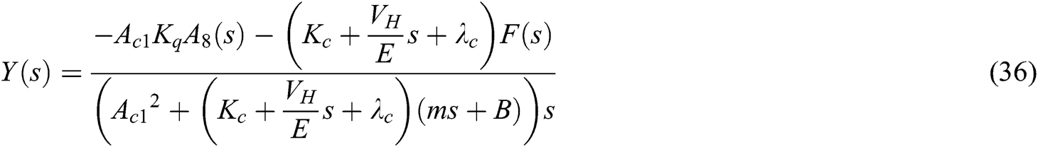
The change in the steering cylinder piston displacement, which is caused by the load interference, is known as the position flexibility of the unit. The reciprocal of the position flexibility is called position stiffness, and the dynamic position stiffness of the system is shown as Eq. (37):
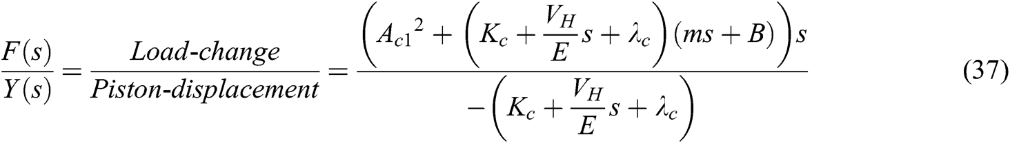
With the increase of the throttle damping opening, kc increases and dynamic position stiffness F/Y(s) increases as well. The larger F/Y(s) is the smaller the hydraulic cylinder piston jitter with the load fluctuations.
Therefore, to ensure the smoothness of the steering operation, it is required that the change of steering load has a small effect on the steering speed and piston displacement, which means greater speed-load stiffness (smaller orifice size A8) and larger dynamic position stiffness (larger orifice area A8). In this paradoxical situation, we should design an appropriate orifice size to meet the needs of steering stability depending on different systems.
4 1D+3D Simulation Model of The Steering System
This article combines AMESim with Virtual Lab Motion to perform 1D+3D mechanical-hydraulic co-simulation. It makes full use of the software’s advantage to accurately analyze the stability of the articulated steering system [14–17].
Previous modes of the equivalent damping orifice mathematical modeling for the steering control valve and the priority valve ignored some key factors, and therefore do not accurately reflect the real valve structure and the actual dynamic working process. However, the HCD (Hydraulic Components Design) model is established in this paper according to their actual structure, by using the Hydraulic Components Design Library provided by AMESim. This completes the 1D model of the steering system. As the HCD library has no rotary valve port, the equivalent model of the steering control valve is established by expanding the spool and sleeve into a planar structure according to their axis, turning it into a translation form.
At the same time, by using Virtual Lab Motion, the 3D dynamics mechanism and tire steering load model of an articulated steering loader is set up, as shown in Fig. 8 based on its actual prototype parameters and full consideration of the tire and ground forces. Finally, the 1D+3D mechanical-hydraulic co-simulation model of the full hydraulic steering system is established by creating the information interaction interface of AMESim with Virtual Lab Motion, as shown in Fig. 9. It can be seen that the model represents the actual structure and relative motion very well, and simplifies the rotary valve model. The AMESim and Virtual Lab Motion co-simulation interaction interface can reasonably reflect the variable interaction between the steering and hydraulic systems.

Figure 8: 3D dynamic model of the steering load
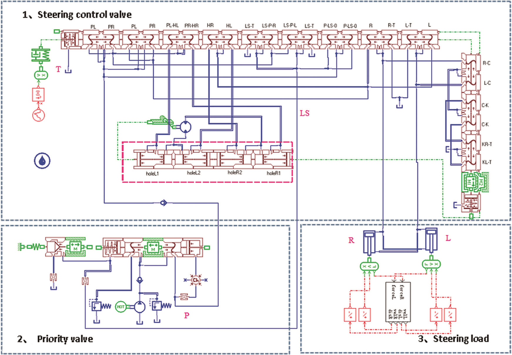
Figure 9: 1D+3D mechanical-hydraulic co-simulation model of the full hydraulic steering system
5.1 Comparison of Bench Test and the Simulation Results
To verify the reliability of the model, a bench testing for the steering control valve and priority valve was carried out. A quantitative pump (96 L/min) was used to supply oil for the test system. The overflow valve simulated steering load and workload. Steering speed is increased to 50 r/min within 1 s, workload and steering load are 0. Comparing simulation and experiment results of the priority valve CF port flow as shown in Figs. 10a and 10b, it can be found that the steady-state value and the overshoot amount of the two curves are consistent. Therefore, the HCD model can quantitatively reflect this steering system’s real performance, and the simulation results based on this model have practical significance on the investigation of the system.
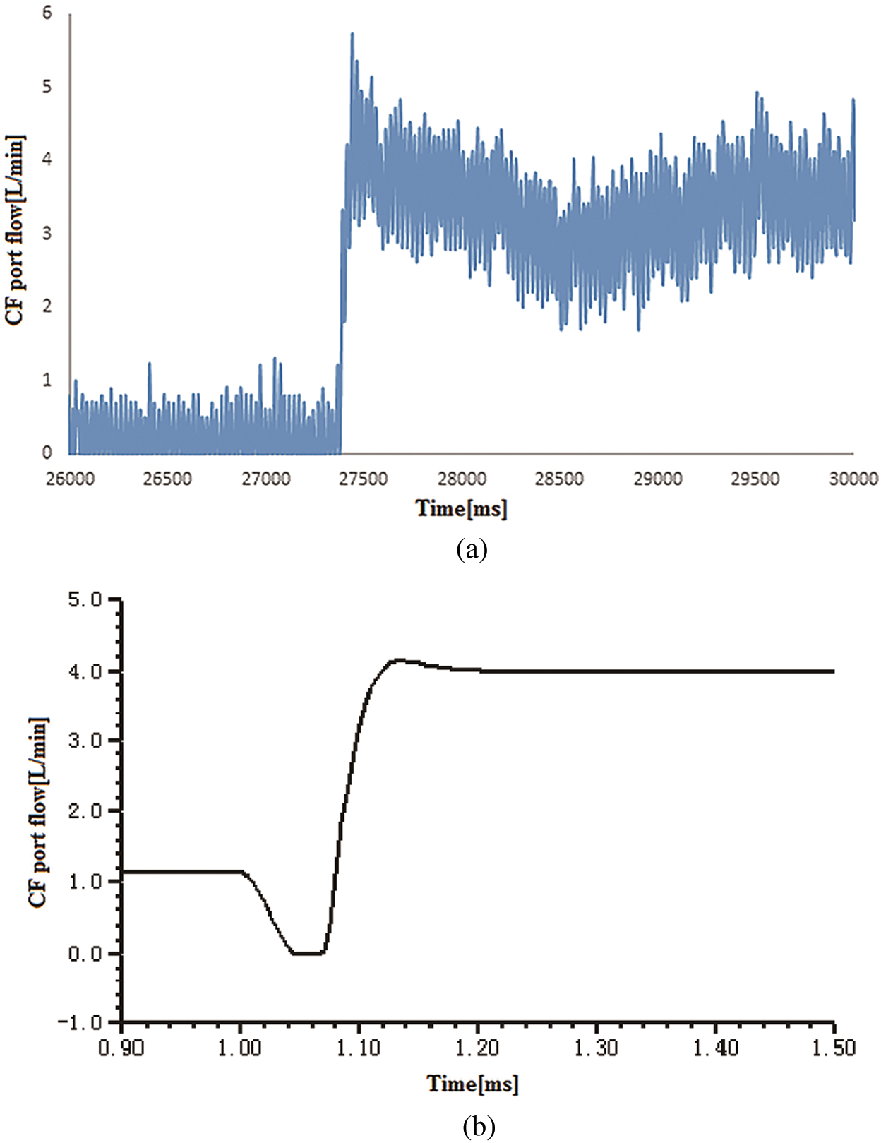
Figure 10: (a) The experimental curve of CF port flow and (b) The simulation curve of CF port flow
5.2 Simulation Analysis for Load-Sensing Characteristic
After setting the wheel speed signal as shown in Fig. 11a, the steering speed slowly increased from 7 r/min to 35 r/min within 5 s, and the flow curves of the priority valve CF and EF port are shown in Fig. 11b. It can be seen that the CF port flow gradually increased with increase in steering wheel speed and at the same time the EF port flow reduced. All of these reflect the characteristics of the dynamic priority valve.
The pressure drops between the CF and LS port of the priority valve and the pressure drop in the steering control valve are shown in Fig. 11c. The results show that the ∆P remained unchanged, while the pressure drop in the steering control valve increased with increased steering speed, ensuring that the steering flow is only affected by the steering control valve’s opening. The simulation confirms the load-sensing function of the system.
Fig. 11d shows that the steering control valve’s spool displacement and the cylinder displacement have a linear relationship and prove that this steering system has good operating performance as a position control system.
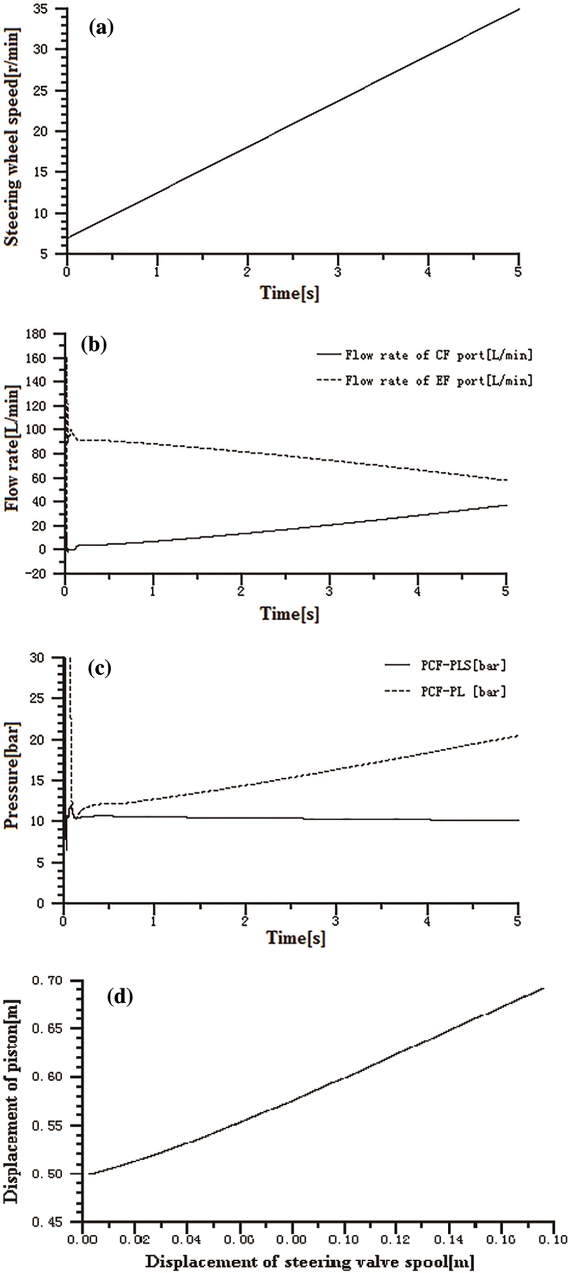
Figure 11: (a) The steering wheel speed signal, (b) Flow rate of priority valve CF and EF port, (c) Pressure drop between CF and LS port  and pressure drop in steering control valve and (d) Relationship of spool displacement and cylinder displacement
5.3 Effect of the Bypass Throttle Damping on Steering Stability
Constant speed signal n = 50 r/min is applied to the steering control valve to simulate the steering wheel’s uniform rotation. The wheel speed signal is shown in Fig. 12a. Simulation analysis was conducted with the system being under two different circumstances: bypass throttle damping or not, System 2 and System 1. This was done by switching the interfaces between the bypass throttle damper and other simulation models. The effects of bypass throttle damping on steering stability were investigated by comparing the simulation results of the two systems in terms of steering cylinder pressure, flow and the velocity of the cylinder piston.
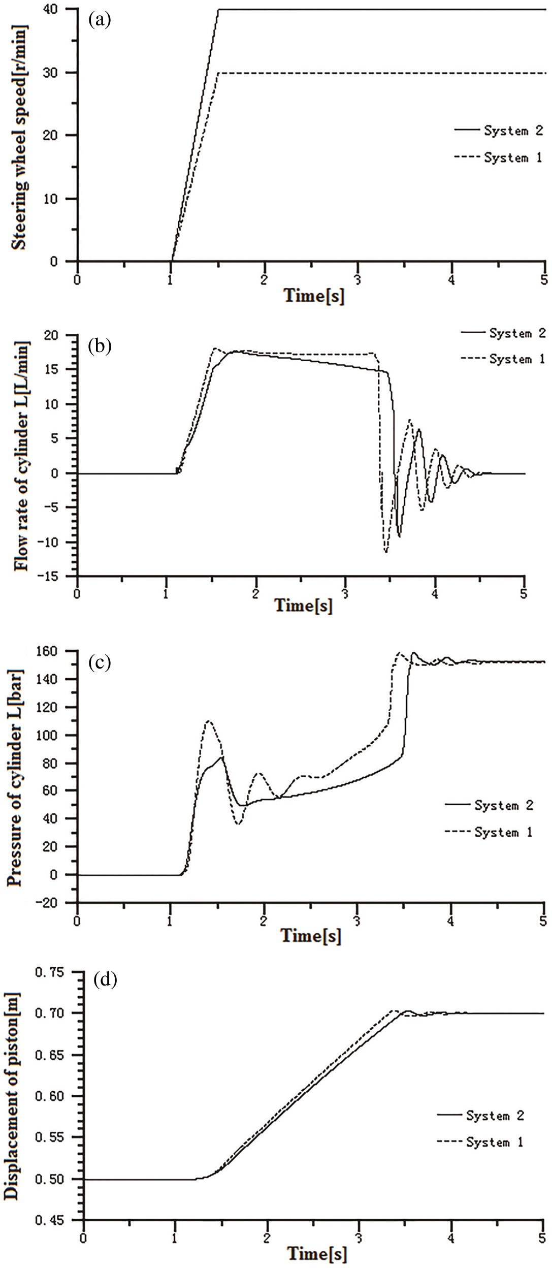
Figure 12: (a) The steering wheel speed signal, (b) Flow rate of steering cylinder, (c) Pressure of steering cylinder and (d) Displacement of steering cylinder
It can be seen in Figs. 12a and 12b that the two systems have almost the same flow coming into the cylinder, at different wheel speed signals. Based on this, we may understand the impact of orifice C8 on cylinder pressure when the flow is the same. Fig. 12c is the steering cylinder pressure of System 1 and System 2. As can be seen, in System 1, which has no bypass throttle damper, there is a higher pressure oscillation at the start of the steering operation, and there is also severe stress shock during the steering process. In System 2, which has a bypass throttle damper, the steering cylinder pressure fluctuation is small, and it reaches a stable stage more quickly. As the cylinder pressure directly affects the cylinder piston’s stability, the bypass throttle damper can optimize the steering pressure response.
The simulation results discussed above show that the bypass throttle damper can effectively reduce pressure fluctuations in the steering cylinder, reduce cylinder piston shock and improve steering stability.
1. By thoroughly analyzing the working principle and actual structure for the essential components of the full hydraulic steering system, the load-sensing priority valve, as well as the steering control valve, mathematical models were established, and the load-sensing characteristics and the effect of steering bypass throttling damper on the steering stability were studied in detail.
2. It has been proved that this full hydraulic steering system has good maneuverability and the bypass throttle damping C8 is highly influential on this system. Orifice size of C8 can be designed appropriately depending on different systems to meet steering stability requirements. The comparison between simulation and bench test results proves that this modeling method and simulation models are accurate and reliable.
3. 1D + 3D mechanical-hydraulic co-simulation of this dynamical system proves that this steering system’s load-sensing characteristics ensure the sensitivity of the steering operation. In addition, the bypass throttle damping C8 is significant in lowering the steering cylinder pressure spikes and pressure shocks, which can improve operational stability and comfortability.
Funding Statement: This work was supported by the National Key Research and Development Program of China, No.2018YFB2000900.
Conflicts of Interest: The authors declare that they have no conflicts of interest to report regarding the present study.
1. C. Altafini. (2019). , “Why to use an articulated vehicle in underground mining operations,” in Proc.–IEEE International Conference on Robotics and Automation, Detroit, MI, USA, pp. 3020–3025. [Google Scholar]
2. Y. Yin, S. Rakheja, J. Yang and P. Boileau. (2018). , “Design optimization of an articulated frame steering system,” Proceedings of the Institution of Mechanical Engineers, Part D: Journal of Automobile Engineering, vol. 232, no. 10, pp. 1339–1352. [Google Scholar]
3. Y. Wang, Z. Liao, S. Shi, Z. Wang and L. H. Poh. (2020). , “Data-driven structural design optimization for petal-shaped auxetics using isogeometric analysis,” CMES-Computer Modeling in Engineering & Sciences, vol. 122, no. 2, pp. 433–458. [Google Scholar]
4. B. A. Johnson, J. L. Brinkman, L. J. Tognetti, C. R. Cesur, P. Spring et al. (2013). , “Hydraulic system having implement and steering flow sharing. Patent, CN102985703A, China. [Google Scholar]
5. J. H. Wang, C. L. Sun, Q. R. Pang, B. Ge, Y. J. Chen et al. (2012). , “Load sensing steering hydraulic system for loading machine. Patent, CN202272517U, China. [Google Scholar]
6. H. T. Huang, J. N. Li, J. W. Zhuo, S. M. Chen, C. M. Chen et al. (2011). , “Improved structure of hydraulic system of loader. Patent, CN201891142U, China. [Google Scholar]
7. S. Fan, H. Ji, Y. Q. Wang and Q. P. Chen. (2019). , “Research on dynamic characteristics optimization of hydraulic priority valve,” Hydraulics Pneumatics & Seals, vol. 39, no. 10, pp. 36–40. [Google Scholar]
8. X. J. Chai, H. G. Hou and Z. Y. Yang. (2006). , “Full-hydraulic steering gear capable of eliminating entrap phenomenon.” Patent, CN2753893Y, China. [Google Scholar]
9. H. G. Hou and W. G. Li. (2004). , “Application of full-hydraulic steering gear capable in forklift truck,” Forklift Truck Technology, vol. 2004, no. 2, pp. 20–22. [Google Scholar]
10. D. M. Ren, G. W. Liu, X. T. Fan, Y. L. Song and P. P. Ma. (2014). , “Steering shake preventing device of loading machine.” Patent, CN203402236U, China. [Google Scholar]
11. T. J. Wang, J. S. Chen, F. Zhao, Q. B. Zhao, X. H. Liu et al. (2013). , “Mechanical-hydraulic co-simulation and experiment of full hydraulic steering systems,” Journal of Jilin University (Engineering and Technology Edition), vol. 43, no. 3, pp. 607–612. [Google Scholar]
12. B. Liu. (1998). , Modern Control Theory. Beijing, China: China Machine Press. [Google Scholar]
13. W. Backe. (1980). , Hydraulic Resistance Circuit Systems. Beijing, China: China Machine Press. [Google Scholar]
14. M. Gipser. (2007). , “FTire – the tire simulation model for all applications related to vehicle dynamics,” Vehicle System Dynamics, vol. 45, no. S1, pp. 139–151. [Google Scholar]
15. S. H. Park, K. Alam, Y. M. Jeong, C. D. Lee and S. Y. Yang. (2009). , “Modeling and simulation of hydraulic system for a wheel loader using AMESim,” in 2009 ICCAS-SICE, Fukuoka, Japan, pp. 2991–2996. [Google Scholar]
16. M. A. Kamel, M. A. Abido and M. Elshafei. (2018). , “Quad-rotor directional steering system controller design using gravitational search optimization,” Intelligent Automation & Soft Computing, vol. 24, no. 4, pp. 795–805. [Google Scholar]
17. Y. Sun, P. He, Y. Zhang and L. Chen. (2011). , “Modeling and co-simulation of hydraulic power steering system,” in Proc.-3rd Int. Conf. on Measuring Technology and Mechatronics Automation, Shanghai, China, pp. 595–600. [Google Scholar]
 | This work is licensed under a Creative Commons Attribution 4.0 International License, which permits unrestricted use, distribution, and reproduction in any medium, provided the original work is properly cited. |