 Open Access
ARTICLE
Topology Optimization of Orthotropic Materials Using the Improved Element-Free Galerkin (IEFG) Method
School of Applied Science, Taiyuan University of Science and Technology, Taiyuan, 030024, China
* Corresponding Author: Heng Cheng. Email:
(This article belongs to the Special Issue: Optimization Design for Material Microstructures)
Computers, Materials & Continua 2025, 83(1), 1415-1414. https://doi.org/10.32604/cmc.2025.059839
Received 17 October 2024; Accepted 06 February 2025; Issue published 26 March 2025
Abstract
In this paper, we develop an advanced computational framework for the topology optimization of orthotropic materials using meshless methods. The approximation function is established based on the improved moving least squares (IMLS) method, which enhances the efficiency and stability of the numerical solution. The numerical solution formulas are derived using the improved element-free Galerkin (IEFG) method. We introduce the solid isotropic microstructures with penalization (SIMP) model to formulate a mathematical model for topology optimization, which effectively penalizes intermediate densities. The optimization problem is defined with the numerical solution formula and volume fraction as constraints. The objective function, which is the minimum value of flexibility, is optimized iteratively using the optimization criterion method to update the design variables efficiently and converge to an optimal solution. Sensitivity analysis is performed using the adjoint method, which provides accurate and efficient gradient information for the optimization algorithm. We validate the proposed framework through a series of numerical examples, including clamped beam, cantilever beam, and simply supported beam made of orthotropic materials. The convergence of the objective function is demonstrated by increasing the number of iterations. Additionally, the stability of the iterative process is analyzed by examining the fluctuation law of the volume fraction. By adjusting the parameters to an appropriate range, we achieve the final optimization results of the IEFG method without the checkerboard phenomenon. Comparative studies between the Element-Free Galerkin (EFG) and IEFG methods reveal that both methods yield consistent optimization results under identical parameter settings. However, the IEFG method significantly reduces computational time, highlighting its efficiency and suitability for orthotropic materials.Keywords
The topology optimization method, which seeks the optimal arrangement of materials structure while satisfying specific properties, is widely used in engineering design. Compared to other structural design methods, such as size optimization and shape optimization, the topology optimization method offers greater design freedom, providing remarkable advantages in applications such as civil engineering [1], aeronautical structures [2], and fiber-reinforced composites [3]. In some extreme environments, anisotropic materials have been developed because isotropic materials cannot fully meet lightweight and high-strength requirements. Anisotropic materials include orthotropic and non-orthotropic materials. Orthotropic materials exhibit differential physical properties in three main directions. They are designed according to actual requirements for strength or stiffness design, giving them high engineering application value in aerospace [4], automobile structures [5], geotechnical [6], and other fields. Compared with non-orthotropic materials, orthotropic materials have simpler constitutive equations, making them easier to study and more convenient for application due to their more mature preparation technology.
Currently, many scholars employ the topology optimization method to study orthotropic materials. Guo et al. [3] proposed a topology optimization framework for stiffness design, addressing the non-smooth characteristics of fiber-reinforced composites using the material substitution method. Montemurro et al. [7] developed a new methodology, drawing on non-uniform rational basis spline entities, the density-based topology optimization method, and the polar formalism for depicting the anisotropy of the continuum. This methodology aims to maximize structural stiffness [8,9]. Based on the complex variable element-free Galerkin (EFG) method, Yang et al. [10] studied the topology optimization of the elasticity problem for both isotropic and orthotropic materials. Moter et al. [11] introduced an innovative technology for orthotropic materials, optimizing material properties in different directions and verifying structural efficiency through experiments. Ye et al. [12] studied the buckling problem of orthotropic plate and shell structures using topological optimization, establishing a model with the objective function of minimizing structural mass subject to buckling critical load constraints. Ichihara et al. [13] employed a parallel optimization method to control the growth of anisotropy in orthotropic composites, achieving better structural design. Therefore, studying orthotropic materials using topological optimization methods holds significant research value, as it can entirely reduce material waste and maximize mechanical properties.
The finite element method (FEM) is a well-established and well-mature numerical method. van Bergen et al. [14] employed the generalized finite element method to analyze two-dimensional electromagnetic problems. Su et al. [15] utilized adaptive scaled boundary FEM to address structural topology optimization based on dynamic response. By combining the generalized FEM with the stable FEM, de Arruda et al. [16] proposed an innovative approach that effectively mitigates most checkerboard issues. FEM has significantly contributed to the field of topology optimization due to its systematic theoretical foundation and a broad range of applications. However, it can lead to grid distortion when addressing complex problems, such as large deformations and crack propagation. Additionally, the checkerboard phenomenon may occur when analyzing topology optimization problems [17]. Based on node approximation, meshless methods [18] do not require mesh subdivision. Consequently, mesh distortion and the checkerboard phenomenon can be avoided. In addition, nodes can be added or removed for a given domain, allowing adaptive computation during the meshless computational process. Currently, the meshless method has achieved better results in solving topology optimization problems for simple structures such as simply supported beams, cantilever beams, L-beams, and plates [19–21].
The EFG [22] method is one of the most widely used approaches to study meshless methods. Zhang et al. combined the EFG method with the topological optimization method to study the anisotropic material properties of thermal structures [23], validating their studies by comparing them with finite element benchmarks. They further explored thermomechanical coupling [24], demonstrating the reliability of the EFG method in these applications. Moreover, orthotropic materials possess optimal periodic structures among anisotropic materials, as revealed by the analysis of material periodic structures [25]. Zhang et al. established a more complex topology optimization algorithm for orthotropic multi-material mechanical structures [26] and multi-material periodic heat transfer structures [27]. Their work demonstrated that orthorhombic heterogeneous multi-materials can achieve more diverse topological configurations and exhibit wider negative Poisson’s ratios than single materials [28]. When addressing complex design spaces, such as composite materials and multi-physical field coupling problems, the demand for computational resources is significant, and computational accuracy will be compromised. Therefore, searching for more efficient optimization algorithms to enhance the efficiency of topology optimization design is essential for engineering applications.
In the study of the EFG method by Zhang et al. [26–28], the shape function is obtained using the moving least square (MLS) method [29]. However, the computational efficiency of the EFG method is not high. In order to address this issue, the improved moving least squares (IMLS) method [30] was proposed, which introduces an orthogonal basis function into the shape function. This modification avoids the occurrence of the singular matrices and improves the computational efficiency. In 2008, the IEFG method was proposed by Zhang et al. [31] based on the IMLS method. Subsequently, the IEFG method has been demonstrated to be effective in various applications, including two-dimensional elasticity problems [31], anisotropic steady-state heat conduction [32], three-dimensional steady convection-diffusion problem [33], the three-dimensional Helmholtz equation [34] and the transient heat conduction problems [35]. Up to now, Wu et al. [36] have been a minority of researchers applying the IEFG method to studying elastic problems in topological optimization. Compared with the EFG method, the IEFG method overcomes the shortcomings of the singular matrix and reduces central processing unit (CPU) calculation time. Given that the mechanical properties of orthotropic materials are superior to those of isotropic materials, studying the topology optimization of orthotropic materials is of significant value. Building on Wu et al.’ s [36] research on isotropic materials, this paper extends the application of the IEFG method to orthotropic materials.
The outstanding contributions of this paper are that it can effectively improve the calculation speed compared with the EFG method in the topological optimization of orthotropic materials and provide an effective meshless method for solving topology optimization problems in engineering.
The research framework is organized as follows. The first section provides an introduction to the study. In the second section, we present the calculation formulas for the numerical solution using the IEFG method. Additionally, the formulas for the solid isotropic microstructures with penalization (SIMP) model used in topology optimization are also given. Moreover, we derive the equations for sensitivity analysis calculations. In the third section, four examples of anisotropic beams are presented to demonstrate the feasibility and efficiency of the IEFG method in solving topology optimization problems. The variation trends of the objective function and volume fraction with increasing iterations are also analyzed. The fourth section draws conclusions regarding the application of the IEFG method to topology optimization problems of orthotropic materials.
2 Topological Optimization Formulas of Orthotropic Materials via the IEFG Method
This section uses the IMLS method to derive the basis function form. Subsequently, the IEFG method is utilized to obtain the solution equation for the elastic mechanics problem of orthotropic materials. Finally, the SIMP model is applied to formulate the topological optimization model for the problem.
In the MLS method [29], the approximate function is defined as
where
m is the number of basis function. The matrix form of weighting function
We employ the Gram-Schmidt orthogonalization method to address the basis function
where
Thus, the matrix
The orthogonalization method of the basis function of the MLS method is referred to as the IMLS method [31]. The new form of the shape function can be presented as follows:
where
Orthogonalization of the basis function significantly enhances the computational efficiency of the MLS approximation.
2.2 The IEFG Method for Orthotropic Elastostatics Problems
The elastostatics model for two-dimensional orthotropic materials is governed by the following elastic equilibrium equations:
The IEFG method is selected to discrete the equilibrium equation for two-dimensional orthotropic elasticity problems. We can obtain the displacement approximate function
where
The matrix expressions of stress
and
In matrix
where
if there is a displacement constraint in the
By substituting Eqs. (22), (25) and (26) into (30), we can derive the following form:
Let
From Eqs. (35)–(42), we derive the final solved equation as follows:
It is important to note that the formulas derived in this paper specifically apply to simple anisotropic single-layer plates.
2.3 The SIMP for Topology of Orthotropic Materials
To achieve optimal results subject to the displacement constraints in topology optimization, we minimize the elastic strain energy derived from the numerical solutions of the solved equations. The optimization model is formulated as follows:
where the initial values
The sensitivity of the objective function is analytical using the adjoint analysis method [31] with relevant formulas provided in the Appendix A. The Lagrange function corresponding to the topology optimization model is given by
where
By substituting Eqs. (46) into (45), the iterative format for design variables is established as follows:
where
where
Bring Eqs. (49) into (50), we can get the value of Lagrange multiplier
In order to demonstrate the advantages of the IEFG method, this section presents four different types of orthotropic material beams. The corresponding program is designed using MATLAB software to verify the feasibility and efficiency. The flowchart of the benchmark example programming is shown in Fig. 1. The single-layer plates considered in this section are made of isotropic materials whose elastic properties and their elastic properties are provided in Table 1.
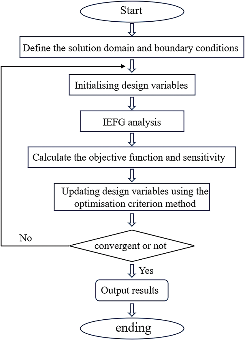
Figure 1: Flow chart of algorithm implementation

3.1 The Orthotropic Clamped Beam Subjected to Uniform Load
Fig. 2 illustrates an orthotropic clamped beam subjected to uniformly distributed loads q = 600 N/m applied at the top. The beam has a height h = 1.0 m and a length l = 10.0 m. The analytical solutions [37] for the displacement of the clamped beam are provided
where s11 = 7.8 × 10⁻⁸ m2/N, s12 = −3.8 × 10⁻⁸ m2/N, s22 = 8.0 × 10⁻⁸ m2/N, s66 = 23.3 × 10⁻⁸ m2/N.
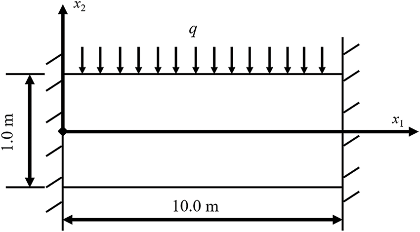
Figure 2: Clamped beam subjected to uniform load
The MATLAB software was employed to design programs. The hardware configuration includes a 12th Gen Intel (R) Core (TM) i7-12700h2.30 ghz, and the software platform used is MATLAB R2023a). The problem domain is discretized into 33 × 13 nodes and 8 × 4 integration units. The scaling parameter of the node in the influence domain dmax is 2.55. The penalty factor α is 1 × 10⁸, the material interpolation penalty factor p is 2.5, and the volume fraction f was specified as 60%. Adopting the EFG method can achieve the result in Fig. 3 for an orthotropic clamped beam subjected to uniform load. The IEFG method yields identical optimization results, thereby validating the accuracy of both approaches. However, the IEFG method offers significant advantages in reducing computational time and enhanced iterative speed. In the subsequent analysis, we focus on the convergence, specific iteration processes, and the computational efficiency of the IEFG method.

Figure 3: Topology optimization result of the EFG method when f = 60%
The convergence of the IEFG method can be assessed by examining the variation of the minimum flexibility value with the number of iterations. In Fig. 4, the minimum flexibility value decreases rapidly from 195.54 at the first iteration to 93.29 by the 15th iteration. Subsequently, the objective function value decreases gradually with increasing iteration count. After 89 iterations, the final objective function value stabilizes at 91.16. This trend demonstrates the efficient convergence of the IEFG method, highlighting its capability to approach the optimal solution rapidly.
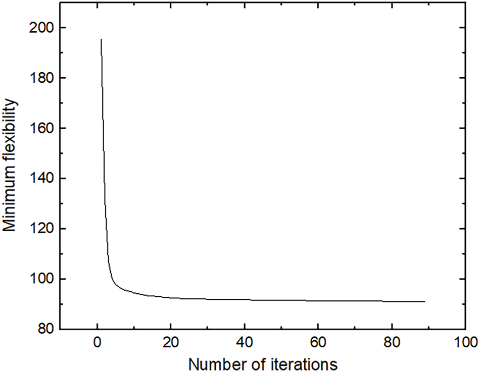
Figure 4: Change of minimum flexibility value for the IEFG method when f = 60%
The specific iterative process is shown in Fig. 5. In the first iteration, the beam’s cross-section consists of four discontinuous parts. By the 15th iteration, discontinuous points appear in the beam’s 1/4 and 3/4 sections from left to right. The point in the upper part of the beam section starts to form a more continuous distribution at 30 iterations. Between iterations 45 and 60, the change in the cross-section slows down, with some uneven points still present in the lower half of the 1/4 and 3/4 sections from left to right. By the final iteration, all discontinuous points disappear entirely. The final optimization results are consistent with the mechanical analysis results, demonstrating a symmetrical cross-section with a uniform distribution and a clear structural layout. This trend highlights the effectiveness of the iterative process in achieving a stable and optimized design.
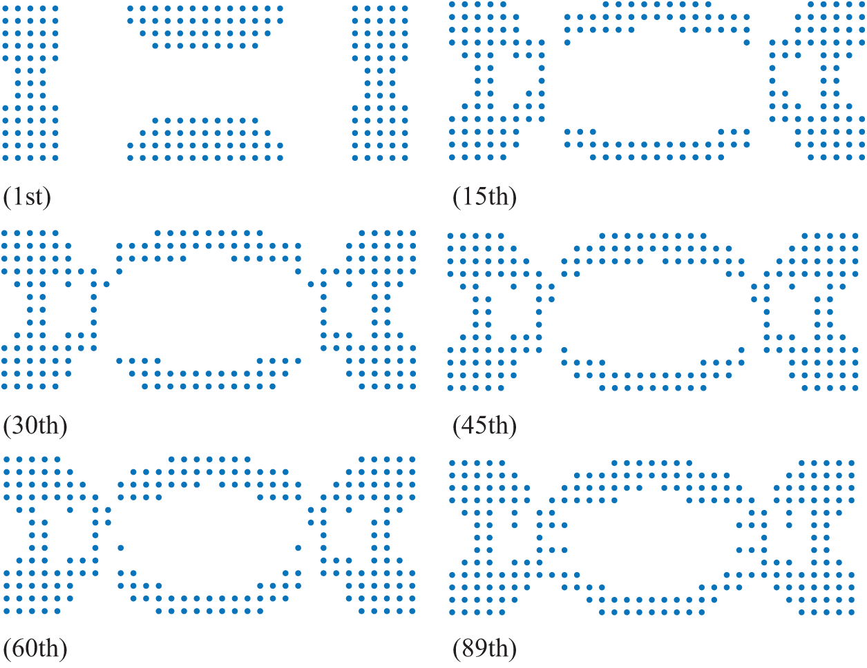
Figure 5: Topology optimization results for the IEFG method when f = 60%
The final optimization result obtained using the IEFG method is consistent with that of the EFG method, as shown in Fig. 3. However, when comparing the CPU computation time of two methods under identical parameter settings (See Table 2), it is evident that the IEFG method significantly reduces computational time.

In addition, we will analyze and present the selection of the parameters. The volume fraction is prescribed, with 50% being the preferred initial value to observe the iterative results. If discontinuous points appear in the final optimization result, we can increase the volume fraction accordingly and re-optimize until a continuous node distribution is consistent with mechanical analysis. The change in volume fraction during the iterative process can be observed, and it should remain unchanged or vary only slightly, providing that other parameters are reasonable. For instance, when the volume fraction f = 50%, the final optimization result (shown in Fig. 6) is not feasible due to discontinuous points in the middle of the optimization result. Discontinuous nodes may imply that the corresponding results are impossible in engineering practice. When the volume fraction is adjusted to 60%, a clear and stable optimization result is obtained in Fig. 5. As the number of iterations increases, the volume fraction remains constant in Fig. 7, indicating that the volume fraction is consistently satisfied as a constraint and is minimally affected by algorithm iteration.

Figure 6: Topology optimization result for the IEFG method when f = 50%
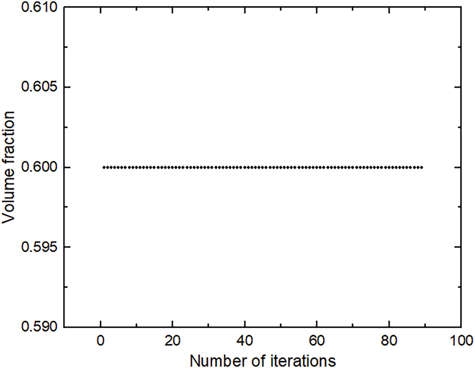
Figure 7: Historical volume fraction for the IEFG method when f = 60%
Furthermore, the scaling parameters of the nodes in the influence domain dmax, the material interpolation penalty factor p, and the penalty factor α will be introduced. Generally, parameter values are initialized at smaller magnitudes and then gradually increased, as larger values tend to extend the corresponding computation time. Specifically, dmax is typically initialized at 1.0 and incrementally increased by 0.1 until a suitable optimization result is achieved. Similarly, the penalty factor α is usually initialized at 1 × 10⁵ and then increased by 10 iteratively. The material interpolation penalty factor p is generally chosen within the range of 2.5 to 4.0. A smaller value of p may lead to many intermediate-density materials in the optimization results. In contrast, a significant value can increase the number of iterations and prolong the optimization time.
It is important to note that the node distribution is optimized starting from an initial configuration of 30 × 10. The integral unit gradually increases from small to large values until a reasonable optimized result is achieved. However, the selection of nodes and units is constrained by the capabilities of actual software and the proportionality of CPU resources. When we attempt to refine the scheme by increasing the number of nodes to 40 × 20, it results in software failure, with an error message indicating that the desired optimization result cannot be achieved.
3.2 The Orthotropic Lamped Beam Subjected to Concentrated Load
The clamped beam, made of orthotropic materials, has a height h = 1.4 m and a length l = 3.0 m. As shown in Fig. 8, it is subjected to a concentrated load F = 1000 N at its midpoint. The flexibility coefficients are s11 = 7.8 × 10⁻⁸ m2/N, s12 = −3.8 × 10⁻⁸ m2/N, s22 = 8.0 × 10⁻⁸ m2/N and s66 = 23.3 × 10⁻⁸ m2/N.

Figure 8: Clamped beam subjected to a concentrated load
We design the computational programs using MATLAB software. The problem domain is discretized into 31 × 15 nodes and 15 × 4 integration units. The remaining parameters are detailed in Table 3. Using the EFG method, we can achieve the result in Fig. 9 for an orthotropic clamped beam subjected to a concentrated load.

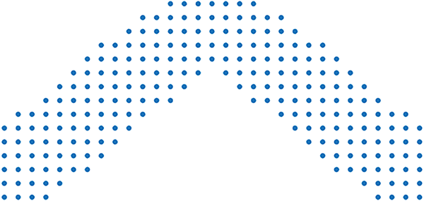
Figure 9: Topology optimization results of the EFG method when f = 50%
The iteration process using the IEFG method is illustrated in Fig. 10. The minimum flexibility value decreases rapidly at the beginning of iteration and then gradually slows down. The iteration concludes after 27 iterations, at which point the final minimum flexibility value is obtained. Fig. 11 presents partial optimization results during the iterative process. In the first iteration, the cross-section of the beam section consists of three discontinuous parts. The irregular part disappears after the fifth iteration. There are a few changes in the number of optimized nodes at the bottom after the 15th iteration. The final optimization result is achieved in 27 iterations, with a clear structure and uniform distribution, consistent with the EFG result shown in Fig. 9.
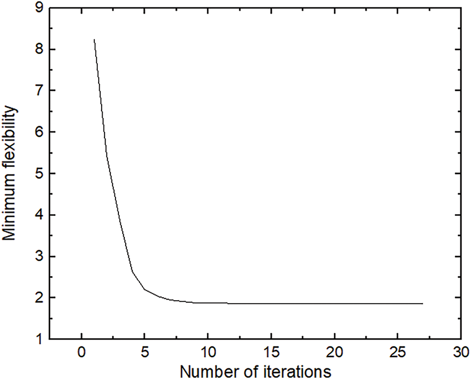
Figure 10: Change of minimum flexibility value for the IEFG method when f = 50%
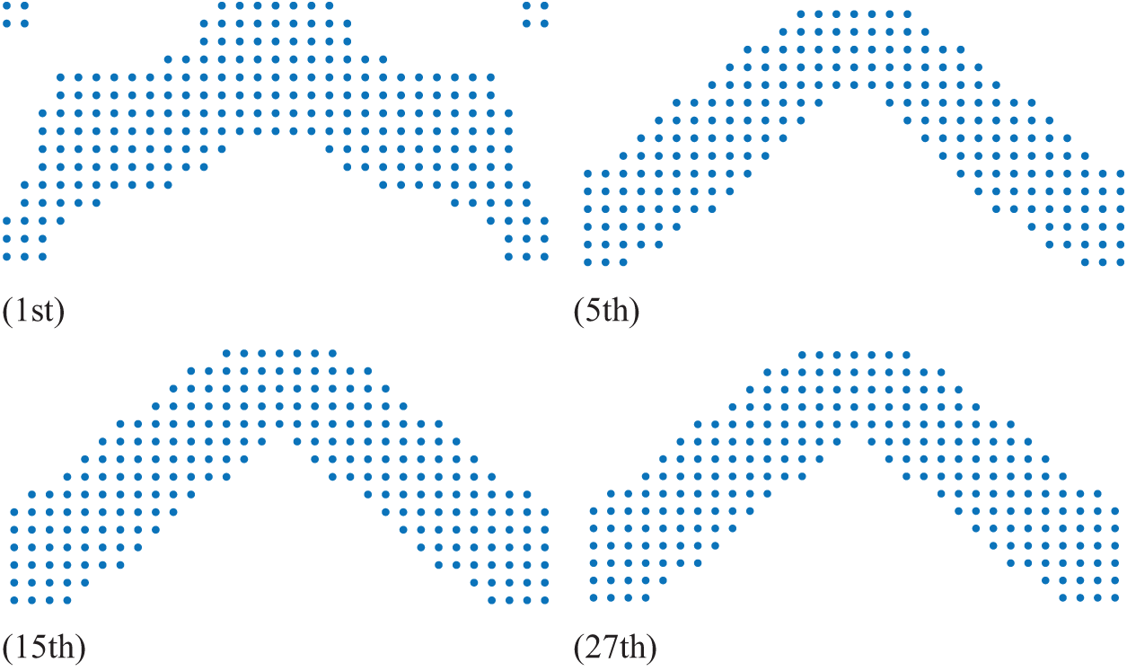
Figure 11: Topology optimization results for the IEFG method when f = 50%
However, when comparing the CPU computation time of the two methods under identical parameter settings (See Table 3), the CPU running time of the EFG method is 1680.02 s. In contrast, the CPU running time of the IEFG method is 1204.10 s. It is shown that the IEFG method reduces the running time by 28.32%.
As illustrated in Fig. 12, the volume fraction remains relatively stable with increasing iteration times. This stability demonstrates that the IEFG method is stable and reliable throughout the iterative process.
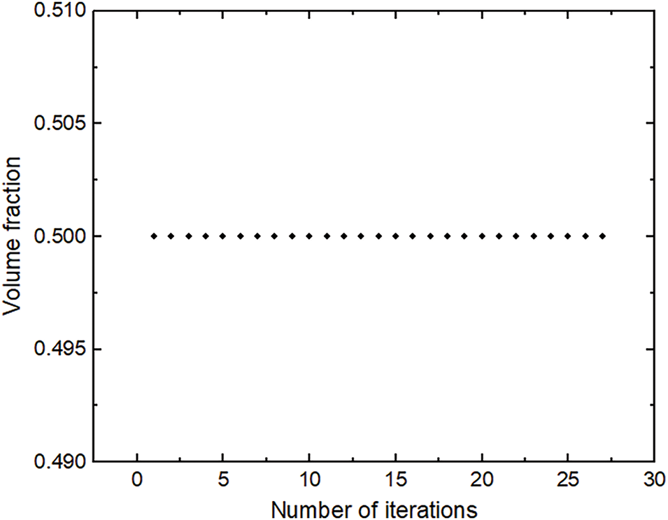
Figure 12: Historical volume fraction for the IEFG method when f = 50%
3.3 The Orthotropic Cantilever Beam Subjected to Concentrated Load
Fig. 13 illustrates an orthotropic cantilever beam subjected to a concentrated load F = 2 × 10⁵ N applied at its left midpoint. The beam has a height h = 1.2 m and a length l = 4.0 m. The analytical solutions for the displacement of the clamped beam, as derived in Reference [38], are given by
where s11 = 8.85 × 10⁻¹² m2/N, s12 = −3.98 × 10⁻¹² m2/N, s22 = 18.98 × 10⁻¹² m2/N, s33 = 35.08 × 10⁻¹² m2/N.

Figure 13: Cantilever beam subjected to a concentrated load
The problem domain is discretized into 42 × 14 nodes and 16 × 5 integration units. The scaling parameter for the nodes in the influence domain dmax is set to 2.5. The penalty factor α is 1 × 10¹⁰, the material interpolation penalty factor p is 3.0, and the volume fraction f is 50%.
Using the EFG method, we can obtain the results in Fig. 14 for an orthotropic cantilever beam subjected to a concentrated load.

Figure 14: Topology optimization result of the EFG method when f = 50%
The variation of the minimum flexibility values with the number of iterations using the IEFG method is illustrated in Fig. 15. The changing trend of the objective function is similar to that observed in the first and second examples. Fig. 16 presents the optimization results during the iteration process using the IEFG method. At the beginning of the iteration, the distribution of points in the optimization results is scattered. As the iteration progresses, the distribution of points begins to concentrate towards the exterior, forming a general shape. Subsequently, internal points gradually emerge, leading to more apparent optimization results. Continuous and precise optimization results are obtained by the end of the iteration.
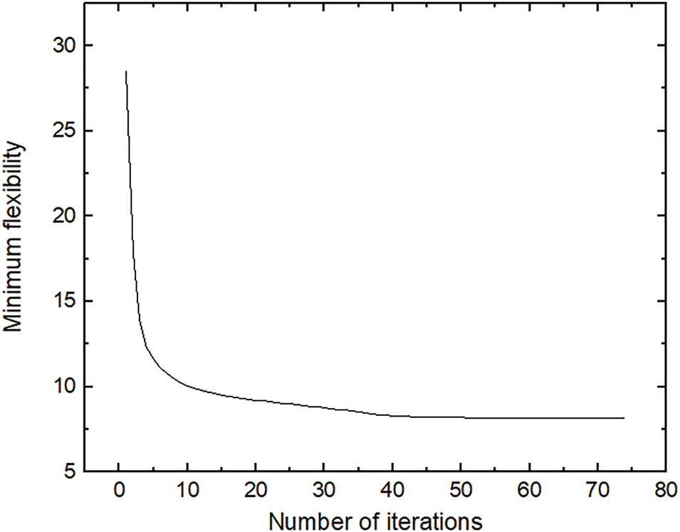
Figure 15: Change of minimum flexibility value for the IEFG method when f = 50%
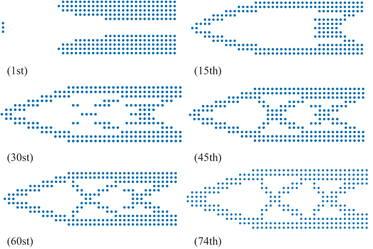
Figure 16: Topology optimization results for the IEFG method when f = 50%
The IEFG method achieves the same optimization results as the EFG method. When comparing the computational efficiency of the IEFG method and the EFG method topology optimization results under identical parameter settings and optimization results, the CPU running time for the EFG method is 2098.97 s, while the CPU running time for the IEFG method is 2024.15 s. Consequently, the IEFG method reduces computational time, thereby enhancing the efficiency of the topology optimization process.
Fig. 17 illustrates the fluctuation of volume fraction during the iteration process. Similar to the observations of the previous examples, the volume fraction’s fluctuation remains stable when employing the IEFG method. This stability highlights the robustness and reliability of the IEFG method in maintaining consistent optimization performance throughout the iterative process.

Figure 17: Historical volume fraction for the IEFG method when f = 50%
3.4 The Orthotropic Simply Supported Beam Subjected to Concentrated Load
Fig. 18 illustrates a simply supported beam with a length of 3.0 m and a height of 1.0 m. The midpoint of the lower boundary is subjected to a concentrated force F = 1 × 10¹⁰ N. The flexibility coefficients are given as s11 = 8.85 × 10⁻¹² m2/N, s12 = −3.98 × 10⁻¹² m2/N, s22 = 18.98 × 10⁻¹² m2/N and s66 = 35.08 × 10⁻¹² m2/N.
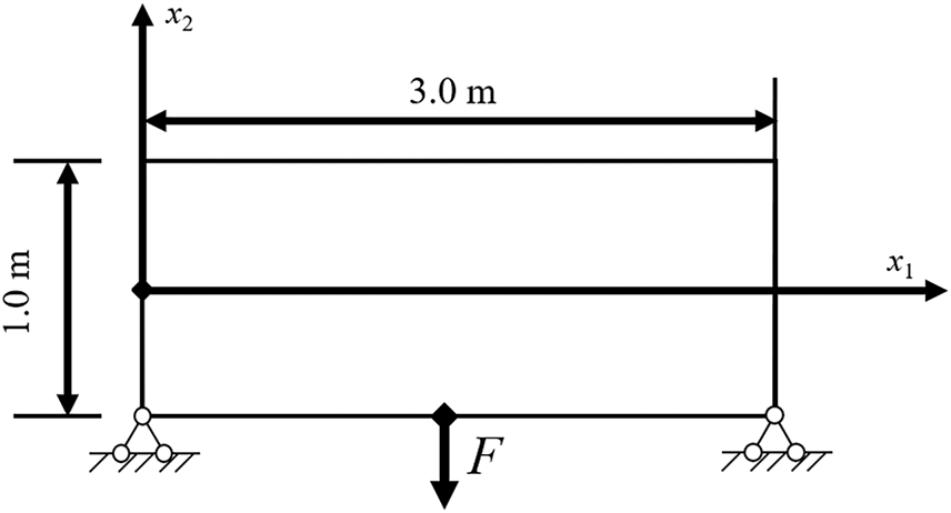
Figure 18: Simply supported beam subjected to a concentrated load
The problem domain is discretized into 31 × 11 nodes and 15 × 5 integration units. The scaling parameter for the nodes in the influence domain dmax is set to 1.1, the penalty factor α is 30 × 1010, the material interpolation penalty factor p is 3.0, and the volume fraction f is 50%.
Using the EFG method, we obtain the results shown in Fig. 19 for an orthotropic simply supported beam subjected to a concentrated load.

Figure 19: Topology optimization result of the EFG method when f = 50%
Fig. 20 illustrates a similar change curve of the objective function value with increasing iteration times, demonstrating the convergence of the IEFG method. Fig. 21 presents the optimization results during the iterative process, showing that the points progressively approach the goal of homogenization and continuity. The final optimization results are clear and consistent with engineering practice.
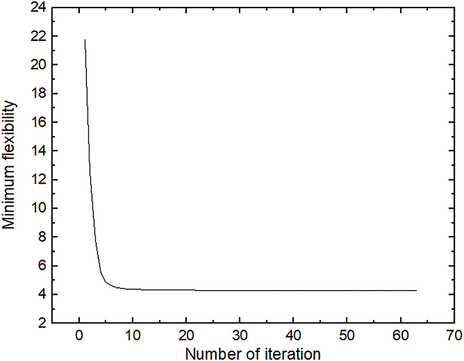
Figure 20: Change of minimum flexibility value for the IEFG method when f = 50%

Figure 21: Topology optimization results for the IEFG method when f = 50%
The IEFG method achieves the same results as the EFG method. When comparing the computational efficiency of the two methods under identical parameter settings, the CPU running time for the EFG method is 973.28 s, while the CPU running time of the IEFG method is 917.51 s. It is shown that the IEFG method reduces computational time, thereby enhancing the efficiency of the topology optimization process.
Similarly, Fig. 22 shows the stable variation of the volume fraction during the iterative process using the IEFG method, further confirming its correctness and stability.
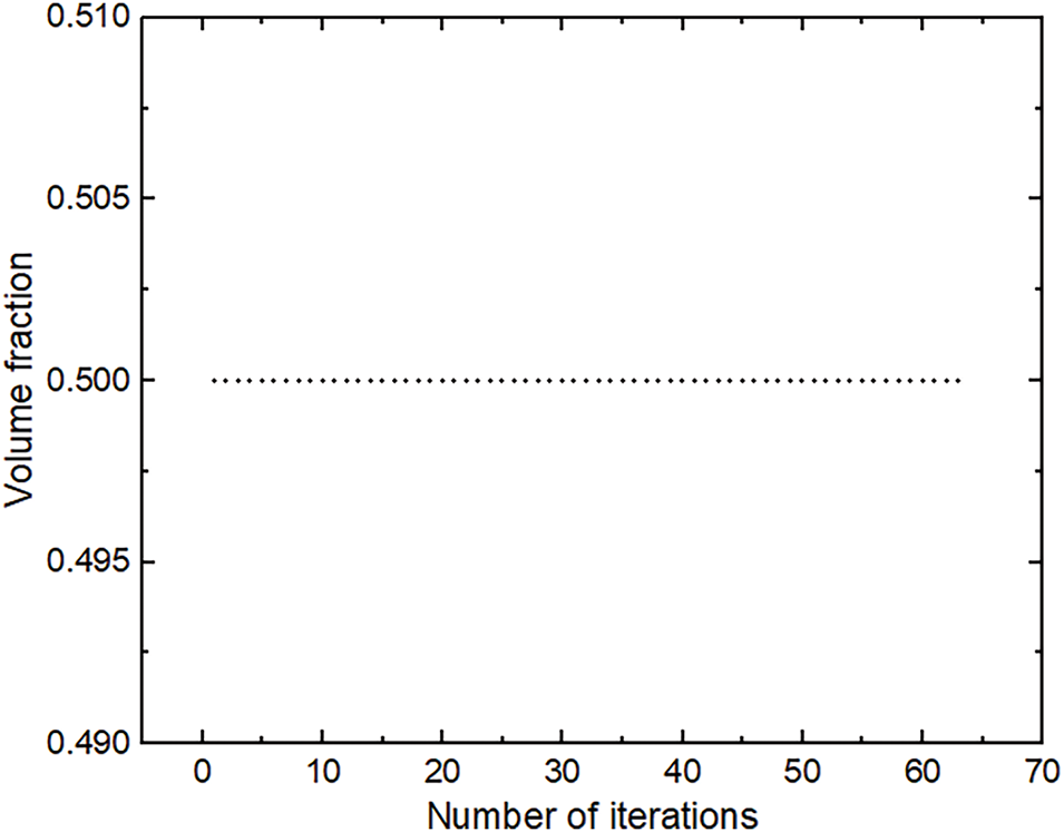
Figure 22: Historical volume fraction for the IEFG method when f = 50%
From the analysis of the IEFG and the EFG methods in Tables 2 and 3 and Figs. 1–22, we can draw the following conclusions:
(1) The IEFG and EFG methods yield identical topology optimization results with clear and distinct structural configurations. Notably, neither method exhibits a grey unit or checkerboard phenomenon. These studies confirm the feasibility of the IEFG method for solving topology optimization problems involving orthotropic materials.
(2) As illustrated by the change in the minimum flexibility value with iteration time, the convergence curve of the objective function exhibits a gradual decrease and stabilization during the topology optimization process. This behavior indicates that the IEFG method proposed in this paper is convergent when applied to the topology optimization problem of orthotropic materials for single-layer plates.
(3) Based on comparing computational time in four examples, the IEFG method demonstrates superior speed to the EFG method. Consequently, the IEFG method proposed in this study efficiently solves the topology optimization problems involving orthotropic materials for single-layer plates.
The limitations of this paper are primarily associated with the scope of the problems addressed. Specifically, the current work focuses solely on the topology optimization of the simple single-layer anisotropic plate. The derivation of formulas and the algorithm implementation for more complex problems, such as those involving multi-layered or non-linear materials, require further investigation. While the IEFG method demonstrates significant computational efficiency for two-dimensional problems, its application to three-dimensional problems remains limited and warrants additional research. Moreover, practical problems involving complex boundaries and geometries also necessitate further exploration of the IEFG method.
In summary, applying the IEFG method for solving topology optimization of orthotropic materials has demonstrated convergence, stability, and significant computational efficiency compared to the traditional EFG method. The IEFG method effectively reduces CPU time, making it a promising approach for addressing complex engineering problems.
Acknowledgement: We would like to thank the editors and reviewers for their valuable comments on the manuscript.
Funding Statement: This work is supported by the Graduate Student Scientific Research Innovation Project through Research Innovation Fund for Graduate Students in Shanxi Province (Project No. 2024KY648).
Author Contributions: The authors confirm contribution to the paper as follows: study conception and design: Wenna He, Heng Cheng; data collection: Wenna He, Dongqiong Liang; analysis and interpretation of results: Wenna He, Yichen Yang; draft manuscript preparation: Wenna He, Heng Cheng. All authors reviewed the results and approved the final version of the manuscript.
Availability of Data and Materials: Not applicable.
Ethics Approval: Not applicable.
Conflicts of Interest: The authors declare no conflicts of interest to report regarding the present study.
Acronyms
| CPU | Central processing unit |
| EFG | Element-free Galerkin |
| FEM | Finite element method |
| IMLS | Improved moving least squares |
| IEFG | Improved element-free Galerkin |
| MLS | Moving least square |
| SIMP | Solid isotropic microstructures with penalization |
The following is to solve the objective function of SIMP using the adjoint analysis method. By introducing the Lagrange multiplier method into the objective function, we can obtain a new equation as
where
Thus, Eq. (48) can be simplified as
where
Therefore, the sensitivity analysis is finally converted into the derivative of the overall stiffness matrix
References
1. Ma C, Qiu N, Xu X. A fully automatic computational framework for beam structure design from continuum structural topology optimization. Struct Multidiscip Optim. 2023;66(12):250. doi:10.1007/s00158-023-03704-8. [Google Scholar] [CrossRef]
2. Stragiotti E, Irisarri FX, Julien C, Morlier J. Efficient 3D truss topology optimization for aeronautical structures. Struct Multidiscip Optim. 2024;67(3):42. doi:10.1007/s00158-024-03739-5. [Google Scholar] [CrossRef]
3. Guo XZ, Zhou KM. Topology optimization for variable stiffness design of fiber-reinforced composites with bi-modulus materials. Optim Eng. 2023;24(4):2745–62. doi:10.1007/s11081-023-09791-2. [Google Scholar] [CrossRef]
4. Khaled B, Shyamsunder L, Hoffarth C, Rajan SD, Goldberg RK, Carney KS, et al. Experimental characterization of composites to support an orthotropic plasticity material model. J Compos Mater. 2018;52(14):1847–72. doi:10.1177/0021998317733319. [Google Scholar] [CrossRef]
5. Rahbar Ranji A, Rostami Hoseynabadi H. A semi-analytical solution for forced vibrations response of rectangular orthotropic plates with various boundary conditions. J Mech Sci Technol. 2010;24(1):357–64. doi:10.1007/s12206-009-1010-3. [Google Scholar] [CrossRef]
6. Dong Y, Zeng B, Song Y, Zhou XJ, Li PC, Zhang F. Numerical study of hydraulic fracture propagation in orthotropic shale reservoirs by using the XFEM. Energy Fuels. 2023;37(17):12919–33. doi:10.1021/acs.energyfuels.3c01627. [Google Scholar] [CrossRef]
7. Montemurro M, Mas A, Zerrouq SE. Topology and anisotropy optimisation of continua using non-uniform rational basis spline entities. Comput Meth Appl Mech Eng. 2024;420(2):116714. doi:10.1016/j.cma.2023.116714. [Google Scholar] [CrossRef]
8. Montemurro M. On the structural stiffness maximisation of anisotropic continua under inhomogeneous Neumann-Dirichlet boundary conditions. Compos Struct. 2022;287(1):115289. doi:10.1016/j.compstruct.2022.115289. [Google Scholar] [CrossRef]
9. Montemurro M, Roiné T. Strength-based topology optimisation of anisotropic continua in a CAD-compatible framework. Adv Eng Softw. 2024;189(2):103591. doi:10.1016/j.advengsoft.2023.103591. [Google Scholar] [CrossRef]
10. Yang YC, Cheng H. Topology optimization for elasticity problem of isotropic and orthotropic materials based on the complex variable element-free Galerkin method. Int J Appl Mechanics. 2024;16(10):2450116. doi:10.1142/S1758825124501163. [Google Scholar] [CrossRef]
11. Moter A, Abdelhamid M, Czekanski A. Direction-oriented stress-constrained topology optimization of orthotropic materials. Struct Multidiscip Optim. 2022;65(6):177. doi:10.1007/s00158-022-03269-y. [Google Scholar] [CrossRef]
12. Ye HL, Wang WW, Chen N, Sui YK. Plate/shell structure topology optimization of orthotropic material for buckling problem based on independent continuous topological variables. Acta Mech Sin. 2017;33(5):899–911. doi:10.1007/s10409-017-0648-9. [Google Scholar] [CrossRef]
13. Ichihara N, Ueda M, Yokozeki T. Penalized anisotropy: controlling anisotropy growth in concurrent optimization of topology and fiber orientation for orthotropic composite materials. J Compos Mater. 2024;58(5):677–88. doi:10.1177/00219983241230379. [Google Scholar] [CrossRef]
14. van Bergen S, Norte RA, Aragón AM. An interface-enriched generalized finite element method for the analysis and topology optimization of 2-D electromagnetic problems. Comput Meth Appl Mech Eng. 2024;421(6234):116748. doi:10.1016/j.cma.2024.116748. [Google Scholar] [CrossRef]
15. Su R, Zhang XR, Tangaramvong S, Song CM. Adaptive scaled boundary finite element method for two/three-dimensional structural topology optimization based on dynamic responses. Comput Meth Appl Mech Eng. 2024;425(1):116966. doi:10.1016/j.cma.2024.116966. [Google Scholar] [CrossRef]
16. de Arruda LS, Martim MB, Góis W, de Lima CR. Topology optimization-unconventional approaches using the generalized finite element method and the stable generalized finite element method. Lat Am J Solids Struct. 2022;19(3):e446. doi:10.1590/1679-78256839. [Google Scholar] [CrossRef]
17. Crespo J, Duncan O, Alderson A, Montáns FJ. Auxetic orthotropic materials: numerical determination of a phenomenological spline-based stored density energy and its implementation for finite element analysis. Comput Meth Appl Mech Eng. 2020;371(124):113300. doi:10.1016/j.cma.2020.113300. [Google Scholar] [CrossRef]
18. Nayroles B, Touzot G, Villon P. Generalizing the finite element method: diffuse approximation and diffuse elements. Comput Mech. 1992;10(5):307–18. doi:10.1007/BF00364252. [Google Scholar] [CrossRef]
19. Sousa L, Oliveira S, Vidal C, Cavalcante-Neto J. A truly meshless approach to structural topology optimization based on the Direct Meshless Local Petrov-Galerkin (DMLPG) method. Struct Multidiscip Optim. 2024;67(7):110. doi:10.1007/s00158-024-03813-y. [Google Scholar] [CrossRef]
20. Zhao F. A meshless Pareto-optimal method for topology optimization. Eng Anal Bound Elem. 2013;37(12):1625–31. doi:10.1016/j.enganabound.2013.09.010. [Google Scholar] [CrossRef]
21. Li SL, Long SY, Li GY. A topology optimization of moderately thick plates based on the meshless numerical method. Comput Model Eng Sci. 2010;60(1):73–94. [Google Scholar]
22. Belytschko T, Lu YY, Gu L. Element-free Galerkin methods. Numer Meth Eng. 1994;37(2):229–56. doi:10.1002/nme.1620370205. [Google Scholar] [CrossRef]
23. Zhang JP, Wang SS, Zhou GQ, Gong SG, Yin SH. Topology optimization of thermal structure for isotropic and anisotropic materials using the element-free Galerkin method. Eng Optim. 2020;52(7):1097–118. doi:10.1080/0305215X.2019.1636979. [Google Scholar] [CrossRef]
24. Zhang JP, Liu TX, Wang SS, Gong SG, Peng JP, Zuo QS. Thermomechanical coupling multi-objective topology optimization of anisotropic structures based on the element-free Galerkin method. Eng Optim. 2022;54(3):428–49. doi:10.1080/0305215X.2021.1872557. [Google Scholar] [CrossRef]
25. Zhang JP, Zhang HM, Chen JH, Liu TX, Peng JP, Zhang DB, et al. Topology optimization of periodic mechanical structures with orthotropic materials based on the element-free Galerkin method. Eng Anal Bound Elem. 2022;143(3):383–96. doi:10.1016/j.enganabound.2022.06.014. [Google Scholar] [CrossRef]
26. Zhang JP, Wu SX, Zhang HM, Zhao L, Zuo ZJ, Wu SY. Topology optimization of orthotropic multi-material structures with length-scale control based on element-free Galerkin method. Eng Anal Bound Elem. 2024;163(10):578–92. doi:10.1016/j.enganabound.2024.03.031. [Google Scholar] [CrossRef]
27. Zhang JP, Chen T, Zhang HM, Wu SY, Zhao L, Zuo ZJ. Topology optimization of orthotropic multi-material microstructures with maximum thermal conductivity based on element-free Galerkin method. Numer Heat Transf Part A Appl. 2024;1–24. doi:10.1080/10407782.2024.2379616. [Google Scholar] [CrossRef]
28. Zhang JP, Zhang ZQ, Zhang HM, Wu SX, Wu SY, Zuo ZJ, et al. Topology optimization of auxetic microstructures with isotropic and orthotropic multiple materials based on element-free Galerkin method. Eng Anal Bound Elem. 2024;166(1):105811. doi:10.1016/j.enganabound.2024.105811. [Google Scholar] [CrossRef]
29. Lancaster P, Salkauskas K. Surfaces generated by moving least squares methods. Math Comput. 1981;37(155):141–58. doi:10.1090/S0025-5718-1981-0616367-1. [Google Scholar] [CrossRef]
30. Cheng YM, Chen MJ. A boundary element-free method for linear elasticity. Acta Mech Sin. 2003;35(2):181–6. [Google Scholar]
31. Zhang Z, Liew KM, Cheng YM. Coupling of the improved element-free Galerkin and boundary element methods for two-dimensional elasticity problems. Eng Anal Bound Elem. 2008;32(2):100–7. doi:10.1016/j.enganabound.2007.06.006. [Google Scholar] [CrossRef]
32. Cheng H, Xing ZB, Peng MJ. The improved element-free Galerkin method for anisotropic steady-state heat conduction problems. Comput Model Eng Sci. 2022;132(3):945–64. doi:10.32604/cmes.2022.020755. [Google Scholar] [CrossRef]
33. Cheng H, Xing ZB, Liu Y. The improved element-free Galerkin method for 3D steady convection-diffusion-reaction problems with variable coefficients. Mathematics. 2023;11(3):770. doi:10.3390/math11030770. [Google Scholar] [CrossRef]
34. Cheng H, Peng MJ. The improved element-free Galerkin method for 3D Helmholtz equations. Mathematics. 2022;10(1):14. doi:10.3390/math10010014. [Google Scholar] [CrossRef]
35. Cheng H, He WN, Zhang J, Cheng YM. The dimension coupling method for 3D transient heat conduction problem with variable coefficients. Eng Anal Bound Elem. 2024;166(7):105839. doi:10.1016/j.enganabound.2024.105839. [Google Scholar] [CrossRef]
36. Wu Y, Ma YQ, Feng W, Cheng YM. Topology optimization using the improved element-free Galerkin method for elasticity. Chin Phys B. 2017;26(8):080203. doi:10.1088/1674-1056/26/8/080203. [Google Scholar] [CrossRef]
37. Chen B, Tian LR, Li DM. Quasi-convex reproducing kernel particle method for orthotropic elasticity. J Huazhong Univ Sci Technol (Nat Sci Ed). 2018;46(1):110–4. [Google Scholar]
38. Huang LX, Li SB, Liu Y, Zhou XJ. The effect of the boundary conditions at fixed-end on the displacement of an orthotropic cantilever beam subjected to a single force. Sichuan Building Sci. 2008;34(5):1008–933. [Google Scholar]
Cite This Article
 Copyright © 2025 The Author(s). Published by Tech Science Press.
This work is licensed under a Creative Commons Attribution 4.0 International License , which permits unrestricted use, distribution, and reproduction in any medium, provided the original work is properly cited.


 Submit a Paper
 Propose a Special lssue
 View Full Text
 Download PDF
 Downloads
 Citation Tools