
 Submit a Paper
 Propose a Special lssue
 Open Access
ARTICLE

LIRB-Based Quantum Circuit Fidelity Assessment and Gate Fault Diagnosis
Laboratory for Advanced Computing and Intelligence Engineering, Information Engineering University, Zhengzhou, 450001, China
* Corresponding Author: Zheng Shan. Email:
Computers, Materials & Continua 2025, 82(2), 2215-2233. https://doi.org/10.32604/cmc.2024.058163
Received 05 September 2024; Accepted 14 November 2024; Issue published 17 February 2025
 View Full Text
 Download PDF
Abstract
Quantum circuit fidelity is a crucial metric for assessing the accuracy of quantum computation results and indicating the precision of quantum algorithm execution. The primary methods for assessing quantum circuit fidelity include direct fidelity estimation and mirror circuit fidelity estimation. The former is challenging to implement in practice, while the latter requires substantial classical computational resources and numerous experimental runs. In this paper, we propose a fidelity estimation method based on Layer Interleaved Randomized Benchmarking, which decomposes a complex quantum circuit into multiple sublayers. By independently evaluating the fidelity of each layer, one can comprehensively assess the performance of the entire quantum circuit. This layered evaluation strategy not only enhances accuracy but also effectively identifies and analyzes errors in specific quantum gates or qubits through independent layer evaluation. Simulation results demonstrate that the proposed method improves circuit fidelity by an average of 6.8% and 4.1% compared to Layer Randomized Benchmarking and Interleaved Randomized Benchmarking methods in a thermal relaxation noise environment, and by 40% compared to Layer RB in a bit-flip noise environment. Moreover, the method detects preset faulty quantum gates in circuits generated by the Munich Quantum Toolkit Benchmark, verifying the model’s validity and providing a new tool for faulty gate detection in quantum circuits.Keywords
With the rapid advancement of quantum technology, quantum computing demonstrates a broad range of application prospects in fields such as biopharmaceuticals, chemical material synthesis, financial technology, and information security [1]. The core advantage of quantum computing lies in its capability to handle specific problems, achieving an exponential increase in time efficiency compared to classical computation. The implementation of quantum algorithms relies on quantum circuits, composed of a series of quantum gates. However, in the Noisy Intermediate-Scale Quantum (NISQ) era, results from quantum computers are not entirely accurate, necessitating quality estimation. It is essential to measure how close the actual output of a quantum circuit is to the ideal result, referred to as quantum circuit fidelity. Previous studies have shown that Direct Fidelity Estimation (DFE) [2] and Mirror Circuit Fidelity Estimation (MCFE) [3] can characterize the fidelity of quantum circuits. Direct fidelity estimation benchmarks quantum circuits by estimating the fidelity of the entire circuit through random selection and measurement of a few Pauli operators. The mirror circuit fidelity estimation method evaluates the fidelity of a quantum algorithm’s execution on actual hardware by constructing and running a series of variant circuits related to the target algorithmic circuit, using randomization techniques to isolate and estimate error mapping during execution. Another method, the ‘full classical’ fidelity estimation, derives the fidelity of the entire circuit by multiplying the fidelity of all gates used in the circuit [4]. The fully classical approach proposes a high demand on the fidelity of quantum gates. Among existing gate fidelity measurements, Randomized Benchmarking (RB) evaluates average gate fidelity using a random sequence of quantum gates, while Quantum Process Tomography (QPT) analyzes gate errors through complete quantum state reconstruction. However, these methods have limitations in assessing the performance of specific quantum gates within complex quantum circuits and large-scale quantum systems. For instance, quantum process layer analysis is less scalable and does not support measurements of multiple qubits. Additionally, it is sensitive to State Preparation and Measurement (SPAM) errors, which, if present, are incorrectly characterized as gate errors, leading to unrealistic fidelity estimates [5]. Direct fidelity estimation methods rely on high-quality randomness for selecting Pauli operators, making them more challenging to implement in practice. RB primarily measures the average performance of gates and does not rely on SPAM errors. However, most RB methods, such as Cross-Entropy Benchmarking (XEB), mirror RB, and binary RB, require benchmarking the entire set of quantum gates [6–8], which poorly represents individual gate information. Benchmarking the entire set of gates significantly increases the required time and resources, especially as the number of qubits grows exponentially.
To overcome the limitations of existing methods, this paper proposes an innovative evaluation strategy, the Layer Interleaved Random Benchmarking (LIRB) method. The method divides the quantum circuit into multiple sublayers that are disjoint and contain only specific quantum gates, applies the IRB independently to each sublayer to obtain the layer fidelity, and multiplies each layer fidelity to estimate the fidelity of the whole circuit. The IRB method is well-suited for evaluating the performance of individual quantum gates, which are more accurately characterized, such as controlled-
The subsequent sections of this paper are organized as follows: the Section 2 introduces the relevant background, the Section 3 demonstrates the experimental model of LIRB, the Section 4 verifies the effectiveness of LIRB in detecting faulty quantum gates in quantum circuits, and the Section 5 concludes the paper.
Within the framework of quantum computing, quantum gates are conceptualized as operators acting on the Hilbert space of qubits. Their essential difference from classical logic gates lies in the fact that quantum gates cannot only perform state flips but also construct multi-state quantum systems through the principles of quantum superposition and quantum entanglement, allowing quantum algorithms to process in parallel. The unitarity of quantum gates is their core property, ensuring the normalization of quantum states and the reversibility of operations, thus avoiding loss or degradation of information.
Single-qubit gates are described by unitary complex matrices. Typical single-qubit gates include the Pauli-X gate, Pauli-Y gate, Pauli-Z gate, and Hadamard gate, which enable bit-flip, phase-flip, and superposition state generation of quantum states. Multi-qubit gates, on the other hand, extend the capabilities of quantum computing by allowing simultaneous manipulation of multiple qubits. Examples include the CNOT gate, Controlled-Z gate, and Cross-Resonance gate, which achieve more complex quantum state transformations through specific qubit interactions. Table 1 shows the matrix forms of common quantum gates.

A quantum circuit is the central structure for realizing algorithms in quantum computing, consisting of a series of quantum gates and measurements. Quantum circuits can be viewed as physical implementations of quantum algorithms, performing computational tasks through precise sequences of quantum gates. Fig. 1 shows a randomly generated two-qubit circuit. The central advantage of quantum circuits is their application of the quantum superposition principle, allowing qubits to exist in a superposition of multiple possible states, thus significantly enhancing the parallel processing of computational tasks. This parallelism provides quantum computers with the potential to outperform conventional computing devices when dealing with complex problems. The physical realization of quantum circuits is also closely related to their carriers—such as ion traps, superconducting qubits, etc.—and these systems typically need to run at very low temperatures to suppress the destruction of quantum coherence by thermal excitation [11].

Figure 1: Randomly generated quantum circuits
Quantum noise is a non-ideal effect generated when a quantum system interacts with its external environment, manifesting in various forms such as bit-flip error, phase-flip error, depolarizing error, amplitude damping error, and phase damping error in quantum information processing [12]. These noise sources include not only thermal fluctuations and electromagnetic interference but also inherent defects in the quantum system, such as material impurities or fabrication defects. To characterize and quantify quantum noise, Quantum State Tomography (QST) and Quantum Process Tomography (QPT) are two important techniques. QST can reconstruct the density matrix of a quantum state, whereas QPT is able to describe in detail the evolution of a quantum state over time. Additionally, Quantum Channel Tomography (QCT) provides a way to characterize the full operational properties of quantum channels [13], crucial for understanding and diagnosing quantum noise. To address the challenges posed by quantum noise, quantum error-correcting codes and quantum error mitigation techniques have emerged. Quantum error-correcting codes, such as Shor and Steane codes, introduce redundancy to detect and correct specific quantum errors by encoding logical qubits onto multiple physical qubits [14]. Quantum error mitigation techniques reduce the impact of noise by optimizing and adjusting the quantum computing process. In the context of superconducting qubits, commonly used methods include zero noise extrapolation, variational quantum algorithms, and randomized compiling, aiming to enhance the accuracy and reliability of computational results [15].
In fault-tolerant quantum computing, the error rate of a quantum gate needs to be below a certain threshold to ensure the accuracy and reliability of the quantum algorithm. Therefore, benchmarking of quantum gates is crucial for assessing the performance of quantum gates in fault-tolerant quantum computing. The general idea of stochastic benchmarking is to implement a sequence of random gates that compose a constant operation and measure the fidelity of each sequence. By averaging the fidelity over different numbers of sequences, the resulting average fidelity will show a tendency to decay as the number of sequences grows. The average error of the whole set of gates can be estimated by fitting the decay curves with a derived model. For circuits, RB provides good average gate fidelity and error rate. It is also highly robust to random noise and errors, and thus can be used as a method to measure circuit fidelity. A variety of modified randomized benchmarking methods have been extended in the last decade. Here, we focus on the three randomized benchmarking methods used in this paper.
2.4.1 Standard Randomized Benchmarking
Standard randomized benchmarking is a method for error characterization of quantum hardware, as shown in Fig. 2. It is performed by inserting a Clifford group after the quantum gates to be measured, then inserting the inverse of the set of added Clifford gates before the circuit measurement. This makes it equivalent to a gate operation and an error accumulation operation. Finally, the survival probability of the sequence is measured, i.e., the probability that the initial state remains unchanged after the sequence of gates. By fitting the survival probability to the length of the sequence, an average error rate can be obtained

Figure 2: Standard randomized benchmarking
where parameters A and B contain errors in quantum state preparation and measurement [16].
2.4.2 Interleaved Randomized Benchmarking
Interleaved Random Benchmarking (IRB) is a method for estimating the average error rate of a particular quantum gate [17]. IRB experiments are based on standard RB experiments, where a new sequence of gates is formed by alternating a sequence of random Clifford gates with the target quantum gates. As long as the effect of the Clifford gate set noise is small on average, the fidelity of the target gate can be measured. As shown in Fig. 3. First, generate a sequence of arbitrary Clifford elements. The first Clifford gate

Figure 3: Interleaved randomized benchmarking
Then, the error-rate per gate is estimated by comparing with the standard randomized benchmarking, as shown in Eq. (3), where
2.4.3 Layer Randomized Benchmarking
Layer Randomized Benchmarking (LRB) is a scalable benchmarking method for quantum processor performance evaluation [18]. As shown in Fig. 4, the method evaluates the independent fidelity of gates in each layer by partitioning the set of two-qubit gates on N qubits into M disjoint layers. This provides an effective and scalable means of analyzing the performance of quantum gates. In the LRB approach, each layer contains a set of independent two-qubit gates that interact with each other within the layer but are separated by a barrier to ensure non-interference. This layering strategy allows the researcher to benchmark the quantum gates in each layer independently, avoiding the difficulties encountered when evaluating the performance of individual gates in complex quantum circuits.

Figure 4: Layer randomized benchmarking process. Reprinted from Reference [18]
Under this layered model, Simultaneous Direct Randomized Benchmarking (SDRB) is used, combining the ideas of Simultaneous Randomized Benchmarking (SRB) and Direct Randomized Benchmarking (DRB). SRB can measure multiple qubits simultaneously, quantifying the crosstalk between the bits effectively. DRB uses the native gates supported in the device to perform the test directly, eliminating the process of transforming and compiling high-level gates to native gates, and supports the measurement of multiple qubits.
LRB applies the SDRB sequence in each layer to accurately measure the error rate of quantum gates. This process begins with the introduction of randomized single-qubit Clifford gates in each layer, followed closely by two-qubit gate operations, and finally by layer-to-layer barriers to isolate the quantum operations in each layer. In this way, the process fidelity of each layer can be extracted from the measured decays
where
Thus, the complete Layer Fidelity (LF) of the entire N-qubit layer can be estimated:
In addition, the Layer RB method employs a normalized quantity, Error Per Logical Gate (EPLG), to represent the average error per two-qubit gate in a layered structure. This quantity is defined by considering the number of two-qubit gates in all layers
In noise-containing quantum computers, the reliability of quantum circuits is affected by noise and faults, which may lead to deviations in the execution of quantum algorithms. Quantum gate faults may originate from hardware defects or control inaccuracies. Unlike environmentally induced random noise, current implementations of quantum logic gates are susceptible to physical faults, such as unwanted phase shifts or rotations, which introduce systematic errors into the system. Error correction protocols can be implemented to address systematic errors, but first, the error-producing gate needs to be identified. This is because error correction requires targeting the faulty gate, not the entire quantum circuit. The goal of fault diagnosis is to accurately localize faulty gates in a quantum circuit, which is important for defect repair during manufacturing, system maintenance, and calibration, and avoiding the use of faulty gates.
3 Circuit Fidelity Testing Based on LIRB
The accuracy of quantum circuits is crucial for the successful execution of quantum algorithms. However, as described in the background chapters, traditional evaluation methods have limitations in terms of accuracy and efficiency. To address these issues, this chapter introduces a novel evaluation strategy: LIRB-based quantum circuit fidelity testing.
The advantages of the IRB method over the SDRB method include more accurately reflecting the average fidelity of individual gates and not requiring operations on multiple qubits simultaneously. This design can evaluate the performance of the target gate in a random noise background while maintaining independence from SPAM errors. Consequently, the fidelity of the entire circuit can be more accurately derived through computation. Furthermore, in fault-tolerant quantum computing, it is crucial to determine whether the error rate of an individual quantum gate is below a specific threshold. The IRB method not only provides an estimate of the average error of a quantum gate, but also offers theoretical bounds on the error. In the ideal case, where random gates are perfect, the fidelity converges to 1, and the error bounds converge to 0. This bound provides upper and lower limits on the estimated value of gate fidelity. In the non-ideal case, where random gates are imperfect, the IRB protocol can still provide an accurate estimate of the target gate error if the gate error is uniformly distributed in a depolarized form [17]. The quantum circuit layering strategy measures the error rates of single-qubit and two-qubit gates, providing a high signal-to-noise ratio. Unlike discrete benchmark tests like Quantum Volume, layered fidelity quantifies the error of each gate in the hierarchical structure and reflects successive hardware improvements. Thus, layering can provide a more accurate, comprehensive, and continuous performance evaluation method, capturing the performance characteristics of quantum processors in large-scale applications.
Overall, LIRB is a quantum gate performance evaluation technique that combines the principles of layer fidelity [16] and the IRB method. This method divides the quantum circuit into multiple disjoint sublayers, each consisting of a set of quantum gate operations, utilizing a barrier to separate the layers. In each sublayer, the IRB method independently evaluates the fidelity of single-qubit and two-qubit gates, and the fidelity of the entire quantum circuit is estimated by multiplication.
The LIRB method is implemented through the following steps: First, all the quantum gates in a quantum circuit are divided based on the qubits they act upon, forming multiple disjoint sublayers. Each layer contains only quantum gates acting on specific qubits. Second, for each layer, an IRB sequence is designed to accurately measure the error rate of the quantum gates. Specifically, the quantum gates in each layer are alternately inserted into a sequence of random Clifford gates. Then, IRB experiments are independently performed for each layer to measure their fidelity, thereby evaluating the quantum gate performance of each layer. Finally, the fidelity results for each layer are multiplied to estimate the fidelity of the entire quantum circuit. The overall fidelity can be approximated by multiplying the process fidelity of the three disjoint subspaces, with a fidelity error range of about one percent [18].
An example of a LIRB experimental flow is illustrated in Fig. 5. In this flow, the quantum circuit QC is divided into three sublayers: QC0, QC1, and QC3, as shown in Fig. 5a. Subsequently, IRB experiments are executed for each of these sublayers, as illustrated in Fig. 5b. The objective is to calculate the fidelity of each sublayer
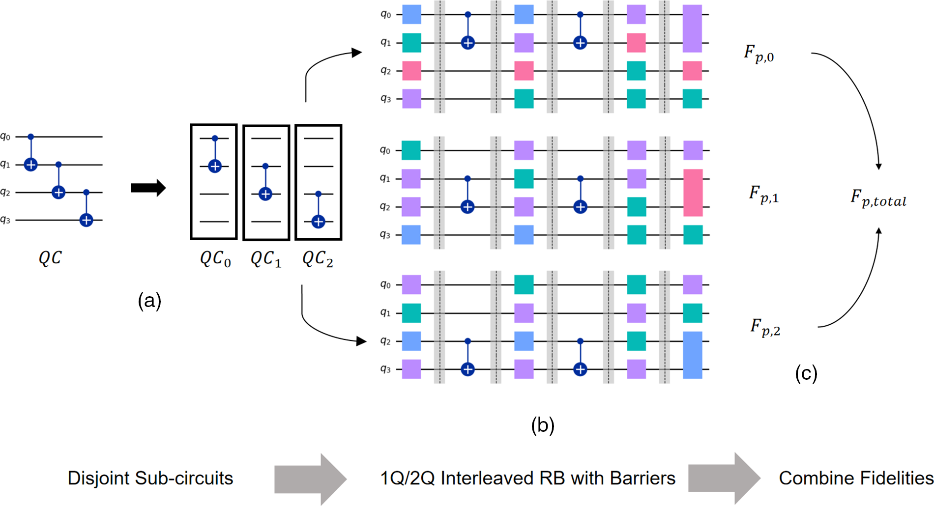
Figure 5: Experimental flow of LIRB
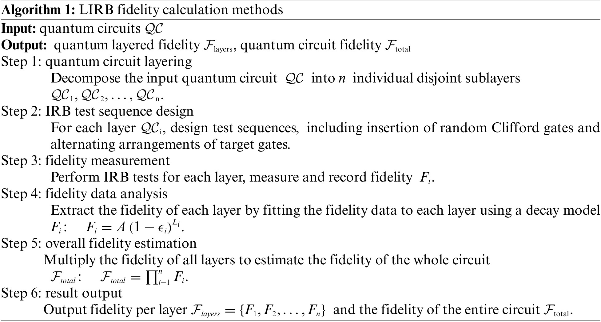
The algorithm for the LIRB fidelity calculation method is presented in Algorithm 1.
3.2 Simulation Verification of LIRB Fidelity
In this study, we compute the theoretical circuit process fidelity and use it as a basis for evaluating the performance of the LIRB method. To fully understand the effect of LIRB, we compare it with existing Layer RB and IRB methods under multiple error models. To ensure that all quantum gate operations are compared on the same time scale, we configured the parameters for the noise simulator as follows: First, we uniformly set the shots in the experiments to 1000, and the backend method is set to automatic. Then we use ‘rz’, ‘sx’, ‘x’, and ‘h’ as the base gate group. The operation time of a single-qubit gate was uniformly set to 1 time unit (i.e., 50), while the operation time of a two-qubit gate was set to 8 times that of a single-qubit gate. Such standardization not only facilitates direct comparison between different gate types, but also provides a consistent frame of reference for subsequent density matrix simulations.
Ambient noise is a key factor affecting the performance of quantum computers. It can significantly change the dynamic behavior of qubits and thus affect the fidelity of the entire quantum circuit. To deeply explore the effect of noise models on the performance of LIRB methods, we applied different noise models to each qubit. These models include, but are not limited to, thermal relaxation, bit flipping, phase flipping, and depolarization noise. This systematic simulation reveals the performance of the LIRB method under different noise conditions and how it compares to the Layer RB and IRB methods. In this paper, we use IBM Qiskit simulators to simulate quantum circuit operation with noise. These simulators are able to model the behavior of quantum circuits under the above noise conditions. These simulators can model the behavior of quantum circuits under the aforementioned noise conditions. In the LRB experiment, we set the qubit chain to 5 qubits based on different circuits, where any two adjacent qubits can form a qubit pair. The LRB sequence length is set from 1 to 200. When setting the noise backend, we only consider applying noise to the CX gate. In the IRB experiment, we ensure that the number of qubits in different circuits is consistent with the number of qubits in the IRB sequence. The sequence length is set from 1 to 200. For thermal relaxation noise parameters, we set different T1 times to 5 microseconds, 25 microseconds, 50 microseconds, 75 microseconds, and 100 microseconds to observe the impact on circuit fidelity under different relaxation times. The noise model is set to ‘noise thermal’. For bit-flip noise parameters, we set the bit-flip probability to 0.05, the noise model to ‘noise bit flip’, the T1 time to 100 microseconds, and apply the bit-flip noise to the X, Y, and Z gates. In order to be able to better compare with the Layer RB method and the IRB method, and to systematically investigate how quantum circuits with different numbers of qubits and circuit depths affect the effectiveness of the LIRB method, we conduct experiments with three quantum circuits as shown in Fig. 6. The environment used for the experimental simulation is shown in Table 2.
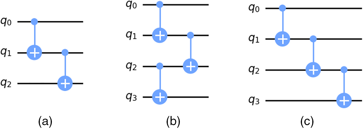
Figure 6: (a) circuit with 3-bit depth of 2 (b) circuit with 4-bit depth of 2 (c) circuit with 4-bit depth of 3

3.2.1 Effects of Thermal Relaxation Time Noise Modeling
T1 and T2 are two key parameters describing the coherent nature of qubits. Observing the variation of the error rate at different T1 and T2 times helps simulate and understand the behavior of qubits under different coherence time conditions. This can provide guidance for designing and optimizing quantum gate operations, such as selecting the optimal gate duration or adjusting the depth of the quantum circuit. Additionally, it allows us to observe how T1 and T2 times affect the variation of cumulative error in quantum gate operations.
First, we compare the error derived in the circuit with the theoretical error, where the process error is given by:
The error in coherence time is calculated as:
In the first set of test experiments, we use a circuit with 3 qubits and a depth of 2 as an example, considering only the incoherent error. The results are shown in Table 3.

In addition, we simulate quantum circuits of different depths but with the same qubit size. The results for a circuit with a depth of 4 are shown in Table 4 as an example.

In the second set of experiments, we simulate the quantum circuit with a depth of 3. The results for this experiment are also shown in Table 5.

From the above fidelity results, it can be seen that under thermal relaxation noise, as the T1/T2 time increases, the circuit fidelity under different methods gradually increases. In the first set of experiments, when the duration was 5 microseconds and under the same circuit depth conditions, the fidelity results of Layer RB, IRB, and Layered IRB for 3-qubit and 4-qubit circuits differed by 11.2%, 15%, and 15.3%, respectively. While at 100 microseconds, the results of the three methods differed by 0.89%, 0.71%, and 0.67%. In the second set of experiments, with the same number of qubits but different circuit depths, when the duration was 5 microseconds, the fidelity results of Layer RB, IRB, and LIRB differed by 9.46%, 9%, and 6.6%, respectively, while at 100 microseconds, the results of the three methods differed by 0.44%, 0.29%, and 0.06%. Therefore, it can be seen that in cases where the T1/T2 times are relatively short, the fidelities evaluated by the three methods for quantum circuits with different qubits and depths will have significant differences. Overall, the fidelity of the LIRB improves by 6.8% and 4.1% compared to the Layer RB and the IRB, respectively, and is closer to the theoretical fidelity value. In particular, the LIRB shows higher fidelity under most relaxation time conditions, indicating its higher accuracy in evaluating the performance of individual quantum gates.
3.2.2 Effects of Bit-Flip Noise Modeling
Next, we study the case with bit-flip noise. In quantum information theory, quantum circuits may be randomly affected by Pauli gates during quantum operations, resulting in erroneous flipping of qubit states. For example, the qubit state flips from
where
It can be seen that a quantum state in a pure state will become a mixed state after passing through a bit-flip channel. In addition to bit-flip noise, qubits may also be affected by phase-flip noise (caused by Pauli-Z gates) and depolarization noise (caused by a mixture of Pauli-X, Pauli-Y, and Pauli-Z gates). These different types of noise may act on the quantum system simultaneously, leading to complex error patterns.
To test and validate the quantum hardware performance, we constructed single bit-flip errors with a probability of 5% using IBM’s noise model, and consider the cases of bit-flip (X-direction) errors, phase-flip (Z-direction) errors, and Y-direction bit-flip errors, respectively.
In the third set of experiments, we simulate a circuit with 3 qubits and a depth of 2. The results are shown in Table 6.

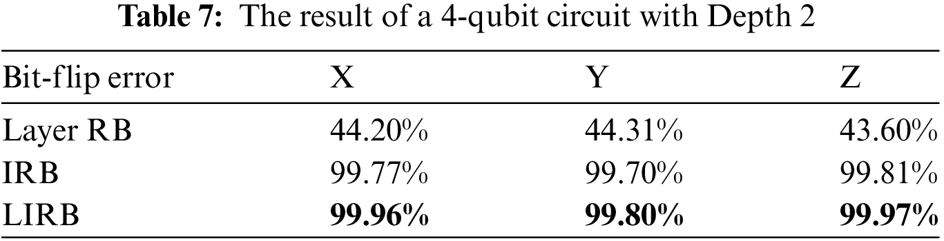
In the fourth set of experiments, we simulated a circuit with 4 qubits and a depth of 2. The results are shown in Table 7.
In the fifth set of experiments, we simulated a circuit with 4 qubits and a depth of 3. The results are shown in Table 8.

From the above three sets of experiments, it can be seen that the fidelity results of LRB differ from those of the IRB method by an average of 39.71%, and from the LIRB method by an average of 40.29%, indicating that Layer RB is more sensitive to bit-flip errors. In the cases of Pauli X, Pauli Y, and Pauli Z bit-flips, the fidelities of LIRB and IRB increased by an average of 0.21%, 0.36%, and 0.5%, respectively, showing a certain improvement over IRB. Compared with Layer RB method, the fidelities increased by an average of 39.85%, 39.76%, and 40.16%, demonstrating the advantage of this method in handling single-type errors.
3.2.3 Evaluation of Computational Resource Consumption
In experiments evaluating quantum circuit fidelity, computational resource usage is a key metric of interest. Our study experimentally verifies and analyzes the performance of various quantum circuit methods concerning computational resource overhead, focusing on quantum gate operation consumption and CPU time and memory usage during data processing and analysis. We treat the execution process of each method holistically and compare the LRB, IRB, and LIRB methods under identical circuit and noise conditions. In this comparative experiment, we calculate average CPU utilization by monitoring CPU usage during each method’s execution and periodically recording data for final analysis. The experiment sets the circuit depth to 5, thermal relaxation noise to 65 microseconds, sequence length to 200, and step size to 30. We conducted multiple repetitions to ensure result reliability.
Table 9 presents the experimental results. The IRB method exhibits the longest execution time but relatively low CPU utilization. In contrast, the LRB method reduces execution time by 77% compared to IRB, with an average CPU utilization of 65%. The LIRB method shows the shortest execution time and an average CPU utilization of 24%. These results indicate that LIRB offers significant advantages in computational overhead.

Through analysis, the experimental results can be attributed to two main factors. First, LRB essentially divides the circuit into layers, with each sublayer tested using sequences from simultaneous direct randomized benchmarking (SDRB). A key characteristic of SDRB is that when multiple qubits are involved, data analysis requires more complex mathematical tools and models to accurately extract useful information. This complexity is the primary reason for the increased memory usage. Second, IRB tests the entire circuit as a whole. However, the inserted target gates may lead to the accumulation of errors, particularly in long sequences. This necessitates a longer duration to average out these errors to obtain an accurate fidelity estimate. In the results, LIRB had the shortest duration of 11.66 s and showed a significant improvement in average CPU utilization compared to LRB. The main reason why the LIRB method is advantageous in terms of shorter duration and lower average CPU utilization is that, compared to the first two methods, when executing the same quantum circuit, LIRB combines the layered characteristics with the low resource consumption of IRB. This allows for testing on disjoint layers, which improves efficiency to some extent. More importantly, the advantage of LIRB lies in its ability to assess the fidelity of quantum circuits while diagnosing the presence of faulty gates, providing a novel approach for fault gate diagnosis.
According to the results of the three experiments mentioned above. This approach can also be applied to more complex noise environments. In practical quantum computing settings, many quantum noise processes can be decomposed into combinations of bit-flip, phase-flip, and depolarizing noise. Among these, bit-flip noise is one of the simplest and most fundamental quantum error models. It is often used as a basis for understanding more complex noise types. The literature [20] also discusses bit-flip and phase-flip errors, as they are mathematically equivalent under certain transformations. This suggests that strategies effective against bit-flip noise can often be adapted to various other noise environments. The LIRB method aims to decompose complex quantum circuits into sublayers to assess each sublayer’s fidelity independently. This approach achieves approximately a 40% improvement in experiments compared to the LRB method. This method has inherent flexibility and can adapt to different noise models, such as mixed noise environments.
4 Fault Detection of Quantum Gates
As described in Section 2.5, when evaluating fidelity of quantum circuits, quantum gate faults can lead to deviations in the fidelity results and affect the performance of quantum algorithms. Therefore, developing effective quantum gate fault detection methods is essential to improve the reliability of quantum computing and the successful execution of quantum algorithms.
In recent years, research on quantum gate fault diagnosis has progressively advanced with the emergence of various novel diagnostic methods and applications. Bera proposed an innovative diagnostic methodology specifically designed for the detection and diagnosis of single-gate faults in quantum circuits [21]. This method utilizes the Binary Tomographic Test (BTT) to generate tests for each gate in the circuit and evaluates the difference between faulty and fault-free gates by comparing the trace of the measurement operators of the two gates. Specifically, the impact of faulty gates on overall circuit performance can be quantified by calculating the difference between the ideal output distribution and the actual output distribution. Furthermore, Bera devised two algorithms to define the types of errors that may occur during the diagnostic process. The first is the False Positive algorithm, which determines the probability of misjudging a non-faulty gate as a faulty gate. The second is the False Negative algorithm, which determines the probability of failing to detect an actual faulty gate. Together, these two algorithms provide a probabilistic framework for fault diagnosis of quantum circuits, thus helping to define the accuracy and reliability of the diagnostic results. Li proposes a diagnostic technique for NISQ circuits, which consists of static diagnosis and dynamic diagnosis. The static diagnosis involves comparing the Output Probability Distributions (OPD) of the quantum circuits under various fault models with the OPDs from actual circuits. The gate with high similarity is identified as the faulty gate. Dynamic diagnosis is carried out using dichotomy, dividing the circuit into multiple sub-circuits, comparing the ideal OPD results of the sub-circuits with the actual ones, and constructing a normal distribution model for the judgment of the fault gate [22]. In addition, hybrid quantum and classical machine learning techniques have been used for fault diagnosis of quantum circuits. For example, Margarite utilizes the K-Nearest Neighbor (KNN) algorithm to diagnose gate faults by comparing the fidelity between the output state and the reference state [23]. This approach not only identifies faulty gates but also quantifies the severity of the fault. However, there are still shortcomings in the existing quantum circuit diagnosis methods. For example, the method in [21] mainly focuses on single-gate fault detection in the ideal case and does not involve quantum gates with noise. Noise in real quantum systems is unavoidable, so it is necessary to consider how to perform effective fault detection in the presence of noise. The methods in the [22,23] are resource intensive and time inefficient.
Given the limitations of existing research, the third part of this paper will focus on the LIRB quantum gate fault detection method. This method takes quantum circuits as inputs and verifies the capability of the LIRB model in detecting quantum gate faults. We will utilize the characteristic of layered IRB experiments, which allows for conducting IRB experiments on independent sublayers, to help detect faulty gates in quantum circuits. The specific experimental steps are shown in Fig. 7. The quantum circuit QC is first divided into n sublayers (Fig. 7a). Then, IRB experiments are performed on each sublayer (Fig. 7b) to derive the fidelity of each sublayer. The fidelity of each sublayer is compared with the ideal fidelity in the error-free case (Fig. 7c) to identify sublayers that are significantly lower than the ideal value and may contain faulty gates. Further diagnostics confirm the presence of faults and determine the type of faults. The experimental results for each layer are repeated several times to ensure reliability, culminating in a comprehensive assessment of the fidelity and faulty gate conditions of the entire quantum circuit.

Figure 7: Flowchart of quantum gate fault detection
To verify the effectiveness of the proposed method, we use the noise model in Qiskit to simulate faulty gates in quantum circuits. Firstly, a test set is built based on the noise model, selected from the MQT bench with GHZ states [24]. The MQT bench can provide an arbitrary number of qubit circuits (2 or more) at different levels, offering a certain degree of versatility. The quantum gate elements in the test sets possess the following properties: T1, T2, the duration of a single-qubit gate, the duration of a two-qubit gate, the maximum error probability of bit flipping, and the size of the test circuit. To construct the test set, we first define the quantum circuits and determine the number of bits and depth of the quantum circuits included in the test set. Next, we select appropriate single-qubit and multi-qubit gates for each circuit, such as Pauli-X, Pauli-Y, and CNOT gates. Then, we introduce faults in the selected quantum gates, including setting different error rates and types of faults, such as depolarization noise and bit-flip. Finally, relevant physical parameters, such as relaxation time and operation time, are set for each quantum gate to simulate actual quantum hardware characteristics. In this experiment, we set up the gate failure model assuming that at most one bit exhibits a failure in any given quantum circuit. We set the maximum error probability for bit flipping to 5%. We choose a 5-bit GHZ circuit and set up three different quantum gate failures.
The specific settings are as follows:
- In Circuit_1, we set the Q0 qubit with relaxation time problem and its relaxation time is set to 5 microseconds.
- In Circuit_2, we introduce depolarizing noise on the CNOT gate associated with bit Q2.
- In Circuit_3, we set a bit Q5 with both bit-flip and phase-flip faults, acting on the CNOT gate associated with that bit.
We applied the LIRB method to a 5-bit GHZ circuit and created a test set table based on the output probability distribution of each circuit. The fidelity of the gates at each layer is used as the key metric, where QCn represents the fidelity at each layer and QC represents the fidelity of the whole circuit. The table is intended to document and compare the actual measurements with the expected results. The results of the IRB experiments for each layer are used to calculate the fidelity of that layer. By recording the fidelity data for each layer and comparing it to the ideal value, we can evaluate the quantum gate performance for each layer and identify those layers that are not performing as expected.
In the same time period, we run the circuit for each case 1024 times. The experimental results are shown in Table 10. QC represents the entire circuit, while QC1~QC5 represent layered sub-circuits. Except for QC1 which contains a single-qubit gate, all other sub-circuits contain only a two-qubit gate. The faulty gates are detected based on the running results in different fault cases. Based on the data from the repeated experiments, we determined the fault tolerance thresholds of 1% and 4% for single-qubit gates and two-qubit gates, respectively. If the fidelity of a quantum gate in a sublayer is lower than these preset thresholds, the sublayer may contain faulty quantum gates. In Circuit_1, the layer fidelity of QC1 is 1.3% lower than the ideal case, indicating a single-qubit gate fault in this layer. The layer fidelity of QC2 is 7.06% lower than the ideal case, indicating a two-qubit gate fault in this layer. In Circuit_2, the layer fidelities of QC3 and QC4 are 4.25% and 6.37% lower than the ideal case, respectively, indicating two-qubit gate faults in these sublayers. In Circuit_3, the layer fidelity of QC5 is 9.75% lower than the ideal case, indicating a two-qubit gate fault in this sublayer. It can be seen that the fidelity of individual sublayers under different preset noise scenarios is relatively low. This result is consistent with the expectation of our experimental design. The success of the LIRB in detecting the faulty gates preset in the design proves the effectiveness of our diagnostic method.

In this paper, we explore a LIRB-based representation of the fidelity of a quantum circuit and the detection of faulty gates within the circuit. Comparative analysis shows that the fidelity results of the LIRB method are closer to the theoretical results for quantum circuits of different dimensions. The LIRB method is similar to the layered RB for detecting two-qubit gates. The method has the following properties: it can characterize the fidelity of quantum circuits more accurately, and it can test for quantum gate faults while evaluating the circuit’s fidelity. Through LIRB experimental validation, we not only verify the validity of the model but also provide a new tool for fault detection in quantum circuits. This helps us to better understand and improve the performance of quantum processors.
However, this model still has room for improvement. For example, in the experiments presented in this paper, we simulated the fidelity verification of LIRB under bit-flip noise and thermal relaxation noise. However, real-world environments often involve multiple types of noise. Therefore, in future research, we plan to develop more complex noise models, including consideration of crosstalk between qubits, to simulate and evaluate the impact of different noise environments on the fidelity results of the LIRB method. Additionally, the experiments in this paper were conducted on the superconducting quantum simulation backend of Qiskit, which may differ from actual conditions. In the next phase of our work, we will conduct experiments on actual quantum processors to validate the effectiveness of the LIRB method. Finally, in experiments for detecting faulty quantum gates, the quality of the random gates must also be considered. If these random gates themselves have significant errors, they may lead to a decline in LIRB’s performance. Furthermore, as the number of qubits increases, the required number of Clifford gates also increases, resulting in greater computational overhead. Therefore, there are still challenges related to resource demands when dealing with large-scale quantum systems.
Acknowledgement: The authors would like to express our sincere gratitude and appreciation to each other for our combined efforts and contributions throughout the course of this research paper.
Funding Statement: The authors received no specific funding for this study.
Author Contributions: The authors confirm contribution to the paper as follows: study conception and design: Mengdi Yang, Feng Yue, Weilong Wang and Zheng Shan; data collection: Haoran He, Benzheng Yuan, Zhiqiang Fan, Chenhui Wang and Danyang Zheng; analysis and interpretation of results: Xiangdong Meng, Pengyu Han, Lixin Wang, Qiming Du and Xuefei Feng; draft manuscript preparation: Mengdi Yang. All authors reviewed the results and approved the final version of the manuscript.
Availability of Data and Materials: Not applicable.
Ethics Approval: Not applicable.
Conflicts of Interest: The authors declare no conflicts of interest to report regarding the present study.
References
1. C. Mangla, S. Rani, and A. Abdelsalam, “QLSN: Quantum key distribution for large scale networks,” Inf. Softw. Tech., vol. 165, no. 9, 2024, Art. no. 107349. doi: 10.1016/j.infsof.2023.107349. [Google Scholar] [CrossRef]
2. S. T. Flammia and Y. -K. Liu, “Direct fidelity estimation from few Pauli measurements,” Phys. Rev. Lett., vol. 106, no. 23, 2011, Art. no. 230501. doi: 10.1103/PhysRevLett.106.230501. [Google Scholar] [PubMed] [CrossRef]
3. T. Proctor et al., “Establishing trust in quantum computations,” 2022. doi: 10.48550/arXiv.2204.07568. [Google Scholar] [CrossRef]
4. A. Vadali, R. Kshirsagar, P. Shyamsundar, and G. N. Perdue, “Quantum circuit fidelity estimation using machine learning,” Quantum Mach. Intell., vol. 6, no. 1, 2024, Art. no. 595. doi: 10.1007/s42484-023-00121-4. [Google Scholar] [CrossRef]
5. A. -M. Kuah, K. Modi, C. A. Rodríguez-Rosario, and E. C. G. Sudarshan, “How state preparation can affect a quantum experiment: Quantum process tomography for open systems,” Phy. Rev. A—Atom., Molec. Optic. Phys., vol. 76, no. 4, 2007, Art. no. 042113. doi: 10.1103/PhysRevA.76.042113. [Google Scholar] [CrossRef]
6. T. Proctor, S. Seritan, K. Rudinger, E. Nielsen, R. Blume-Kohout and K. Young, “Scalable randomized benchmarking of quantum computers using mirror circuits,” Phys. Rev. Lett., vol. 129, no. 15, 2022, Art. no. 150502. doi: 10.1103/PhysRevLett.129.150502. [Google Scholar] [PubMed] [CrossRef]
7. S. Boixo et al., “Characterizing quantum supremacy in near-term devices,” Nat. Phys., vol. 14, no. 6, pp. 595–600, 2018. doi: 10.1038/s41567-018-0124-x. [Google Scholar] [CrossRef]
8. J. Hines, D. Hothem, R. Blume-Kohout, B. Whaley, and T. Proctor, “Fully scalable randomized benchmarking without motion reversal,” PRX Quantum, vol. 5, no. 3, 2024, Art. no. 19. doi: 10.1103/PRXQuantum.5.030334. [Google Scholar] [CrossRef]
9. S. Garion et al., “Experimental implementation of non-Clifford interleaved randomized benchmarking with a controlled-S gate,” Phys. Rev. Res., vol. 3, no. 1, 2021, Art. no. 013204. doi: 10.1103/PhysRevResearch.3.013204. [Google Scholar] [CrossRef]
10. R. Harper and S. T. Flammia, “Estimating the fidelity of T gates using standard interleaved randomized benchmarking,” Quant. Sci. Technol., vol. 2, no. 1, 2017, Art. no. 015008. doi: 10.1088/2058-9565/aa5f8d. [Google Scholar] [CrossRef]
11. M. A. Shafique, A. Munir, and I. Latif, “Quantum computing: Circuits, algorithms, and applications,” IEEE Access, vol. 12, no. 19, pp. 22296–22314, 2024. doi: 10.1109/ACCESS.2024.3362955. [Google Scholar] [CrossRef]
12. M. A. Nielsen and I. L. Chuang, Quantum computation and quantum information. USA: Cambridge University Press, pp. 325–335, 2010. [Google Scholar]
13. G. Gutoski and N. Johnston, “Process tomography for unitary quantum channels,” J.Math. Phy., vol. 55, no. 3, 2014, Art. no. 032201. doi: 10.1063/1.4867625. [Google Scholar] [CrossRef]
14. Z. J. Chen et al., “Advances in quantum error correction based on superconducting quantum systems,” (in ChineseActa Phys. Sin., vol. 71, no. 24, pp. 1, 2022. doi: 10.7498/aps.71.20221824. [Google Scholar] [CrossRef]
15. Z. Cai et al., “Quantum error mitigation,” Rev. Mod. Phys., vol. 95, no. 4, 2023, Art. no. 045005. doi: 10.1103/RevModPhys.95.045005. [Google Scholar] [CrossRef]
16. J. Kelly et al., “Optimal quantum control using randomized benchmarking,” Phys. Rev. Lett., vol. 112, no. 24, 2014, Art. no. 240504. doi: 10.1103/PhysRevLett.112.240504. [Google Scholar] [PubMed] [CrossRef]
17. E. Magesan et al., “Efficient measurement of quantum gate error by interleaved randomized benchmarking,” Phys. Rev. Lett., vol. 109, no. 8, 2012, Art. no. 080505. doi: 10.1103/PhysRevLett.109.080505. [Google Scholar] [PubMed] [CrossRef]
18. D. C. McKay, I. Hincks, E. J. Pritchett, M. Carroll, L. C. G. Govia and S. T. Merkel, “Benchmarking quantum processor performance at scale,” 2023. doi: 10.48550/arXiv.2311.05933. [Google Scholar] [CrossRef]
19. M. A. Nielsen, “A simple formula for the average gate fidelity of a quantum dynamical operation,” Phys. Lett. A, vol. 303, no. 4, pp. 249–252, 2002. doi: 10.1016/S0375-9601(02)01272-0. [Google Scholar] [CrossRef]
20. D. Gottesman, “Stabilizer codes and quantum error correction,” 1997. doi: 10.48550/arXiv.quant-ph/9705052. [Google Scholar] [CrossRef]
21. D. Bera, “Detection and diagnosis of single faults in quantum circuits,” IEEE Trans. Comput. Aided Des. Integr. Circuits Syst., vol. 37, no. 3, pp. 587–600, Mar. 2018. doi: 10.1109/TCAD.2017.2717783. [Google Scholar] [CrossRef]
22. Y. -M. Li, C. -Y. Hsieh, Y. -W. Li, and J. C. -M. Li, “Diagnosis of quantum circuits in the NISQ era,” in 2023 IEEE 41st VLSI Test Symp., San Diego, CA, USA, 2023, pp. 1–7. doi: 10.1109/VTS56346.2023.10140030. [Google Scholar] [CrossRef]
23. M. L. LaBorde, A. C. Rogers, and J. P. Dowling, “Finding broken gates in quantum circuits: Exploiting hybrid machine learning,” Quant. Inf. Process., vol. 19, pp. 1–8, 2020. doi: 10.1364/FIO.2020.FTu8D.4. [Google Scholar] [CrossRef]
24. N. Quetschlich, L. Burgholzer, and R. Wille, “MQT Bench: Benchmarking software and design automation tools for quantum computing,” Quantum, vol. 7, 2023, Art. no. 1062. doi: 10.22331/q-2023-07-20-1062. [Google Scholar] [CrossRef]
Cite This Article
 Copyright © 2025 The Author(s). Published by Tech Science Press.
This work is licensed under a Creative Commons Attribution 4.0 International License , which permits unrestricted use, distribution, and reproduction in any medium, provided the original work is properly cited.
 Downloads
 Citation Tools