 Open Access
ARTICLE
Toward Analytical Homogenized Relaxation Modulus for Fibrous Composite Material with Reduced Order Homogenization Method
1 HEDPS, Center for Applied Physics and Technology (CAPT), Department of Mechanics and Engineering Science, Peking University, Beijing, 100871, China
2 State Key Laboratory for Turbulence and Complex Systems, Peking University, Beijing, 100871, China
* Corresponding Author: Zifeng Yuan. Email:
(This article belongs to the Special Issue: Multiscale and Multiphysics Computational Methods of Heterogeneous Materials and Structures)
Computers, Materials & Continua 2025, 82(1), 193-222. https://doi.org/10.32604/cmc.2024.059950
Received 21 October 2024; Accepted 04 December 2024; Issue published 03 January 2025
Abstract
In this manuscript, we propose an analytical equivalent linear viscoelastic constitutive model for fiber-reinforced composites, bypassing general computational homogenization. The method is based on the reduced-order homogenization (ROH) approach. The ROH method typically involves solving multiple finite element problems under periodic conditions to evaluate elastic strain and eigenstrain influence functions in an ‘off-line’ stage, which offers substantial cost savings compared to direct computational homogenization methods. Due to the unique structure of the fibrous unit cell, “off-line” stage calculation can be eliminated by influence functions obtained analytically. Introducing the standard solid model to the ROH method enables the creation of a comprehensive analytical homogeneous viscoelastic constitutive model. This method treats fibrous composite materials as homogeneous, anisotropic viscoelastic materials, significantly reducing computational time due to its analytical nature. This approach also enables precise determination of a homogenized anisotropic relaxation modulus and accurate capture of various viscoelastic responses under different loading conditions. Three sets of numerical examples, including unit cell tests, three-point beam bending tests, and torsion tests, are given to demonstrate the predictive performance of the homogenized viscoelastic model. Furthermore, the model is validated against experimental measurements, confirming its accuracy and reliability.Keywords
Fiber-reinforced composites offer advantages such as lightweight properties, high strength, extended maintenance intervals, and corrosion resistance, making them widely used in the aerospace and automotive industries [1–5]. Thermosetting or thermoplastic matrices with cylindrical microstructures exhibit transversely isotropic viscoelastic behavior, as documented in the literature [6,7]. The overall mechanical behavior of fibrous composites is analyzed using multiscale methods. These methods provide detailed insights into the underlying mechanisms, enabling material performance optimization and guiding innovative material design.
Initially, homogenization methods for viscoelastic composites were based on the correspondence principle. Micromechanical theoretical schemes developed for elastic composites were extended to viscoelastic composites to estimate their effective elastic moduli in the Laplace domain. Various approaches, including mean-field homogenization methods [8–10], the asymptotic homogenization method [11–13], the variational principle [14,15], and the sequential linearization approach [16], have been employed to simulate viscoelastic composites. Results obtained in the Laplace domain are then transformed back to the time domain to determine the effective response of the viscoelastic materials. However, performing an analytical inverse transform is usually too complex, so the macroscopic response in the time domain can only be obtained through numerical inversion [12] or approximate inversion methods [17], which can be costly and less accurate.
To overcome the limitations of the Laplace transformation, various homogenization methods have been developed to operate directly in the time domain [18–20]. Mean-field homogenization methods, initially formulated for linear elastic composite materials, have since been extended to address nonlinear behaviors, such as elastoplastic [21,22] and viscoelastic [23] responses, among others. These extensions are typically implemented by linearizing local constitutive laws incrementally, an approach necessitated by the Eshelby problem’s assumption that mechanical interactions within phases are purely elastic. Additionally, stress and strain fields within each phase are approximated as phase averages, treating them as homogeneous. However, in nonlinear problems, where stress and strain distributions are inherently non-uniform across phases, this approximation can lead to an over-stiffness issue. To address this challenge, techniques such as the isotropization method [24] and higher-order theories [25] have been proposed. Bleiler et al. [26] introduced a tangent second-order homogenization method to estimate the effective mechanical response of fibrous composites with hyperelastic, anisotropic, and incompressible phases. Furthermore, Barral et al. [27] advanced the Mori-Tanaka method by incorporating a modified transformation field analysis (TFA) approach first proposed by Dvorak and his coworkers [28] and introducing a specialized coating between fibers and the matrix, effectively mitigating over-stiffness in the analysis of fiber-reinforced composites. In the TFA method, the inelastic strains are considered as given eigenstrains. This method assumes that eigenstrains in each phase of the composite are piecewise constant, this lower-order approximation can lead to inaccurate solutions for overall properties. To overcome the problem, Michel et al. [29,30] have introduced the nonuniform transformation field analysis, where full field calculations take place and the plastic behavior is traced with the help of several plastic modes. Strategies such as subdividing each phase into numerous partitions, using asymptotically consistent eigenstrain fields have also been employed [31].
The asymptotic homogenization method is a mathematically rigorous methodology developed by Sanchez-Palencia [32], Bensoussan and Alain [33]. Compare to the Mean-field homogenization method, it effectively captures the interactions between different phases within composite materials, enabling more precise predictions of their overall performance. It has been proved that the considered fields converge towards the homogeneous macroscopic solution as the micro-structural parameter
Multiscale computational techniques based on the finite element method such as
To decrease computational costs at the meso-scale without significantly compromising solution accuracy, the reduced-order-homogenization (ROH) multiscale method was developed, combining the asymptotic homogenization method with transformation field analysis (TFA) [43,44]. The ROH method was first used in composite plasticity and failure analysis [43,45], and higher-order ROH methods have been developed for three-scale nonlinear problems [46–49]. In this paper, a two-phase model with the assumption of one partition per phase is employed for fiber-reinforced composites. Due to the unique structure of the fiber-reinforced unit cell, analytical transformation influence functions can be derived. Based on ROH theory, an analytical homogenization constitutive model for unidirectional fibrous composites is proposed, eliminating the need for computational homogenization. As demonstrated in the following section, the proposed model does not exhibit significant over-stiffness and helps reduce computational time.
This paper is organized as follows. In Section 2, we introduce the analytical viscoelastic fibrous composites constitutive model based on the ROH homogenization method. Special cases where the fiber volume fraction approaches zero are considered to confirm the model’s consistency under extreme conditions. We investigate the impact of material parameters of each component on the relaxation times of the homogenized viscoelastic material. Additionally, numerical implementation specifics for the proposed model are detailed in this section. Section 3 presents numerical verifications of the proposed model through three sets of numerical examples: unit cell tests, three-point beam bending tests, and torsion tests. Experimental results from the literature are used to validate the proposed constitutive model. Conclusions are provided in Section 4.
In this section, we introduce an analytical framework to determine homogenized viscoelastic material properties for the fibrous composite material based on the so-called reduced order homogenization (ROH) method. Here we assume the fiber phase follows transversely isotropic symmetry and keeps elastic that
On the other hand, the matrix phase is viscoelastic and described by the standard solid model [50], and the stress response is written as the following form:
where
Here
respectively. Here the quantities associated with the fiber and the matrix phase are marked with superscription
Our goal is to obtain an analytical homogeneous relaxation tensor
based on given material properties of the fiber and the matrix phase without computational homogenization process, where
2.1 Reduced Order Homogenization (ROH) for Fibrous Composite Material
The reduced-order homogenization (ROH) method is based on two key assumptions: 1) It is possible to distinguish between two length scales associated with macroscopic and microscopic phenomena; 2) The microstructure is sufficiently regular to be considered periodic; 3) The material within the same partition maintains a consistent status throughout, which reduces computational costs at the meso-scale. A complete derivation of the ROH method would be too extensive for this section, so we will present only the essential formulas. For a detailed explanation of the methodology, please refer to reference [44]. The fibrous composite material consists of the fiber and matrix phases. We introduce eigenstrains
where
where
Since the fiber phase keeps elastic, we can obtain
by the standard solid model defined in Eq. (2), with consideration of material isotropy Eqs. (3a) and (3b), and define
By linear elastic stiffness tensor of the fiber phase and the matrix phase given in Eqs. (1) and (9), respectively, we can first obtain the homogenized elastic stiffness tensor
where
Usually, the fibrous composite material is assumed to satisfy the transversely isotropic symmetry so that the linear elastic stiffness tensor can be written with Hill’s constants
The fiber phase also is transversely isotropic, where its Hill’s constants are written as
where
2.2 Analytical Influence Functions for Fibrous Composite Material
The elastic strain and eigenstrain influence functions are usually evaluated by solving a number of finite element problems over the given fibrous unit cell [44]. In this manuscript, we aim to provide an analytical method to evaluate those functions with given linear homogenized stiffness tensor
First of all, the elastic strain influence functions satisfy the following constraint that [44]
One can obtain the elastic strain influence functions by Eqs. (10) and (15) [44]:
In other words, for a two-phase unit cell, as long as
Next, we continue to evaluate the eigenstrain influence functions. Define the following supportive tensors:
and
However,
Due to the symmetry of fibrous unit cell, one can use only
and for the eigenstrain influence tensors, we also have (
From Eqs. (21) and (22), we can quickly obtain the following results:
which means the axial strains of the matrix and the fiber phases are the same and equals to the macroscopic axial strain
2.3 Viscoelastic Model for the Fibrous Composite Material
In this section, we propose a homogenized viscoelastic model with the analytical elastic strain and eigenstrain influence functions. Substituting Eqs. (8) into (7b) with
where
Thus we obtain
Next, substituting Eqs. (26) into (24) yields
By solving the system of ordinary differential equations in Eq. (27), we obtain the matrix phase strain
The solutions for the shear strains
respectively. With
here
So far, we are able to find the matrix phase strain
by considering Eq. (23). For the rest components, expand Eq. (7b) into
Finally, one can introduce a fourth-order tensor
First, from Eq. (31), we can obtain the components corresponding to
From Eqs. (28a) and (28b), we obtain
In addition, from Eq. (29b) and (29c), we obtain
and all other components of
Substituting Eqs. (33) into (11) yields
2.4 Model Consistency in an Extreme Case
In this section, we exam the homogenized viscoelastic properties of the fibrous composite material by letting
By setting
Considering the aforementioned conditions, we can obtain
which traces back to the pure matrix case.
2.5 Influence of Component Parameters on Homogenization Relaxation Times
In this section, we analytically calculate the homogenization relaxation times
We first investigate the influence of fiber parameters on homogenized relaxation times. Parameters are chosen as detailed in Table 1, with one parameter varied within specified ranges. Fig. 1a illustrates the impact of fiber volume fraction on viscoelastic behavior: as the fiber fraction increases, the relaxation times also increase, indicating that, in our research, fibrous composites with higher fiber content tend to exhibit more solid-like characteristics in the homogenized state. It is noteworthy that relaxation time associated with the fiber direction is always equal to the matrix relaxation time, as indicated by Eq. (36), implying that the viscoelastic behavior in this direction is solely influenced by matrix components, while viscoelastic behavior in other directions is influenced by both fiber and matrix components. Fig. 1b demonstrates how homogenized relaxation time varies with changes in

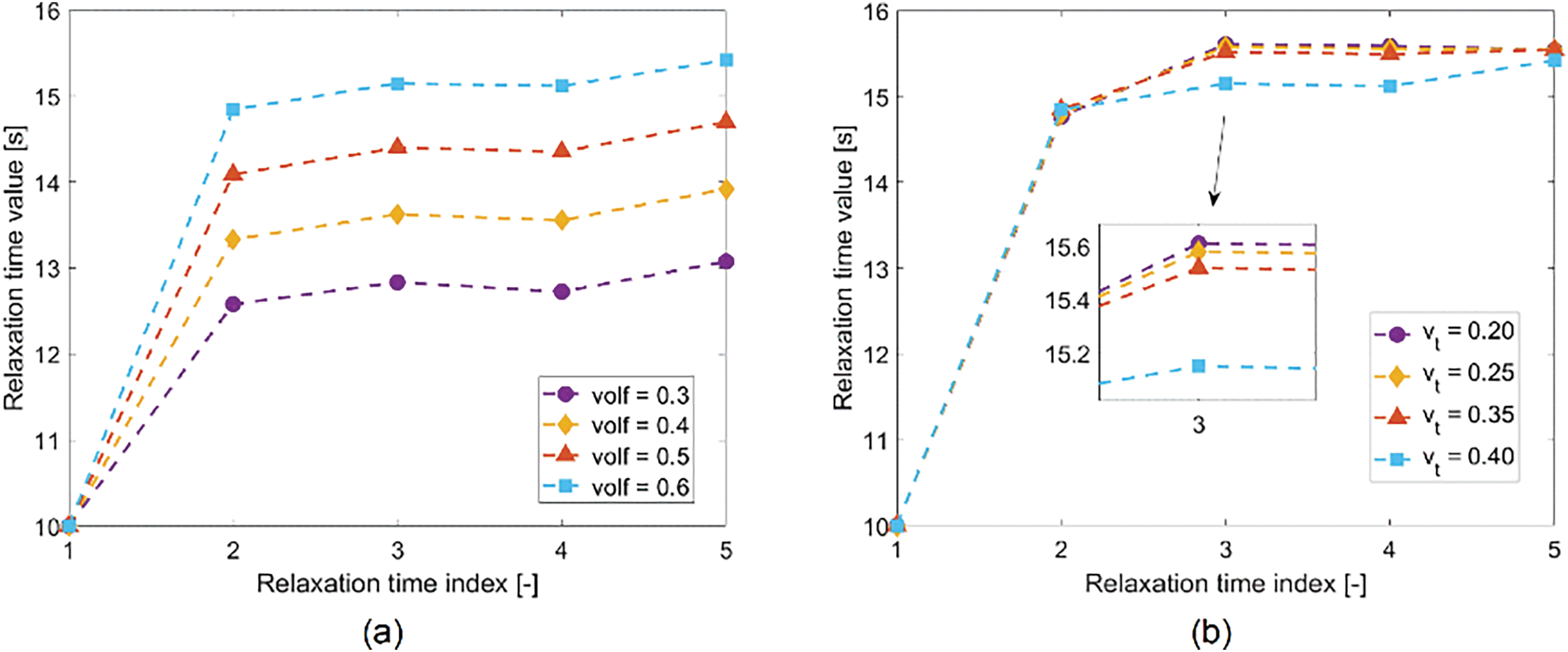
Figure 1: Influence of fiber parameters on homogenized relaxation times: (a) Fiber volume; (b) Poisson ratio in the transverse plane
Next, we explore the influence of matrix parameters on homogenized relaxation times. As shown in Fig. 2a, an increase in
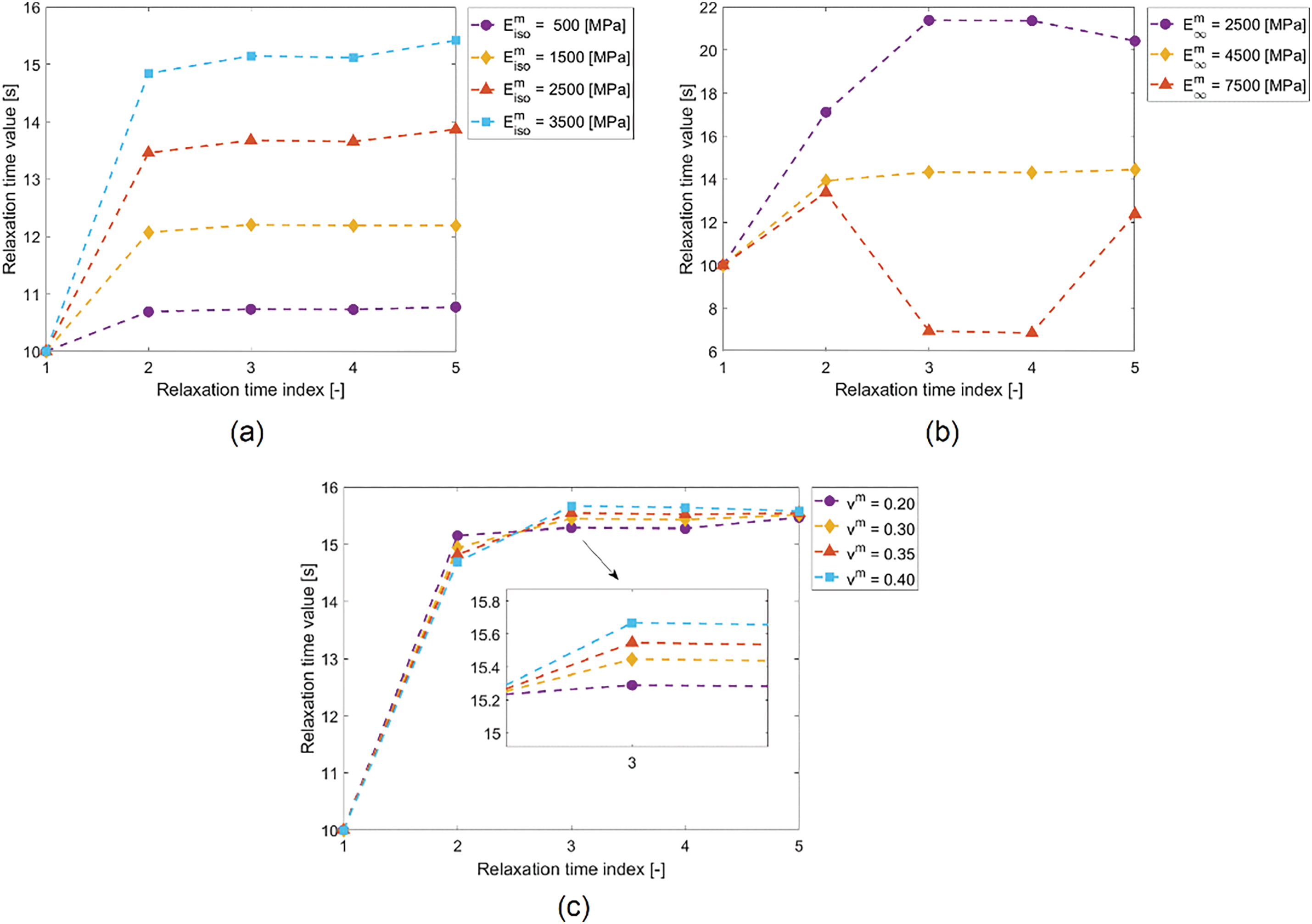
Figure 2: Influence of matrix parameters on homogenized relaxation times: (a) Relaxation modulus
In this section, we briefly introduce the numerical algorithm for the homogenized viscoelastic model of fibrous composite material. In finite element analysis, we update material stress as well as consistent tangent modulus over one increment
again
The numerical integration scheme is the same as the classic viscoelastic stress update procedure. For example:
With
From the convolution form in Eq. (36), define the following
From (41a) and (41b), we can obtain
and
Similar equations can be derived for
In addition, one can derive
Specifically,
3 Numerical Examples and Validation
In this section, we propose several groups of numerical examples to verify and validate the proposed analytical homogenized viscoelastic model for fibrous composite materials. The numerical examples and validation are organized as follows: In Section 3.1, unit cell tests under uniaxial tension and pure shear conditions are performed to demonstrate consistency between FEM and the proposed homogenized model under a uniform strain field. In Sections 3.2 and 3.3, we introduce pure bending beam experiments and torsion experiments to further investigate the ability of the proposed homogenized method. In Section 3.4, theoretical predictions are compared with experimental results from the literature to validate prediction accuracy. All simulations are conducted using the commercial FEM software ABAQUS/Standard 2022 with a user material subroutine (UMAT).
We first verify the accuracy of the homogenized viscoelastic model using a uniform strain field problem. We explicitly construct a unit cell of the fibrous composite material for the direct numerical simulation (DNS), where the fiber is transversely isotropic elastic and the matrix follows the standard solid model, as depicted in Fig. 3. The size of the unit cell is set as
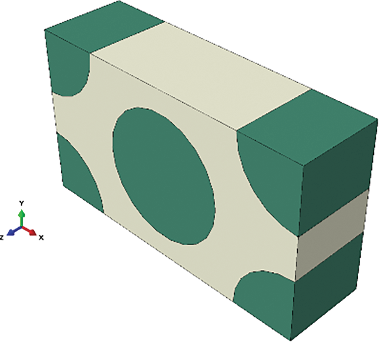
Figure 3: Unit cell model with size of
Various numerical tests are proposed with different fiber volume fractions:
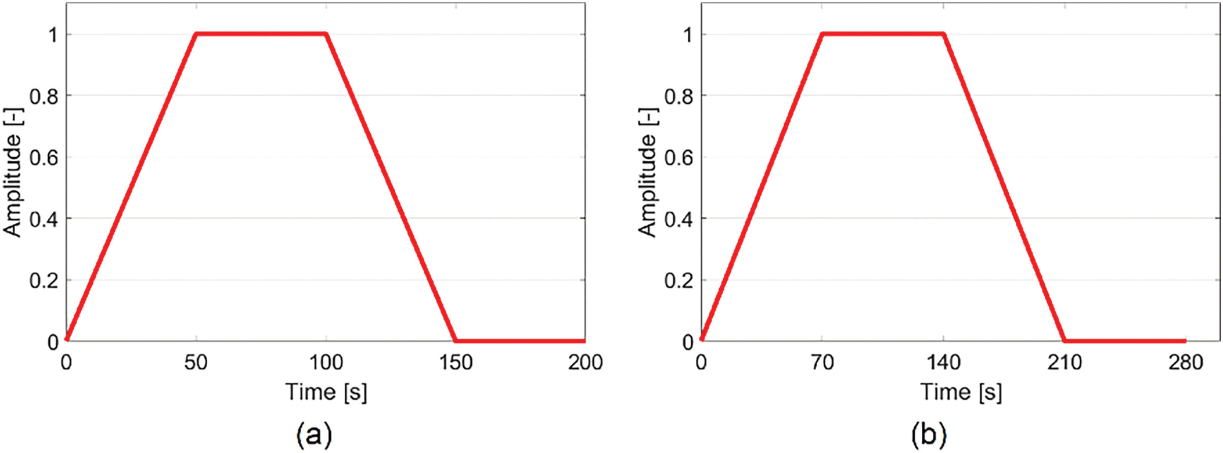
Figure 4: Loading rates: (a) Unit cell test; (b) Pure bending and torsion tests
A group of DNS simulations is depicted in Fig. 5, while the corresponding group of one-element simulation using the proposed homogenized viscoelastic constitutive model is depicted in Fig. 6. Clearly, the DNS results provide more detail but at a higher computational cost. To avoid redundancy, not all simulation results will be displayed. Figs. 7 and 8 show comparison of strain-stress responses between the DNS and the homogenized model (HM for short) for
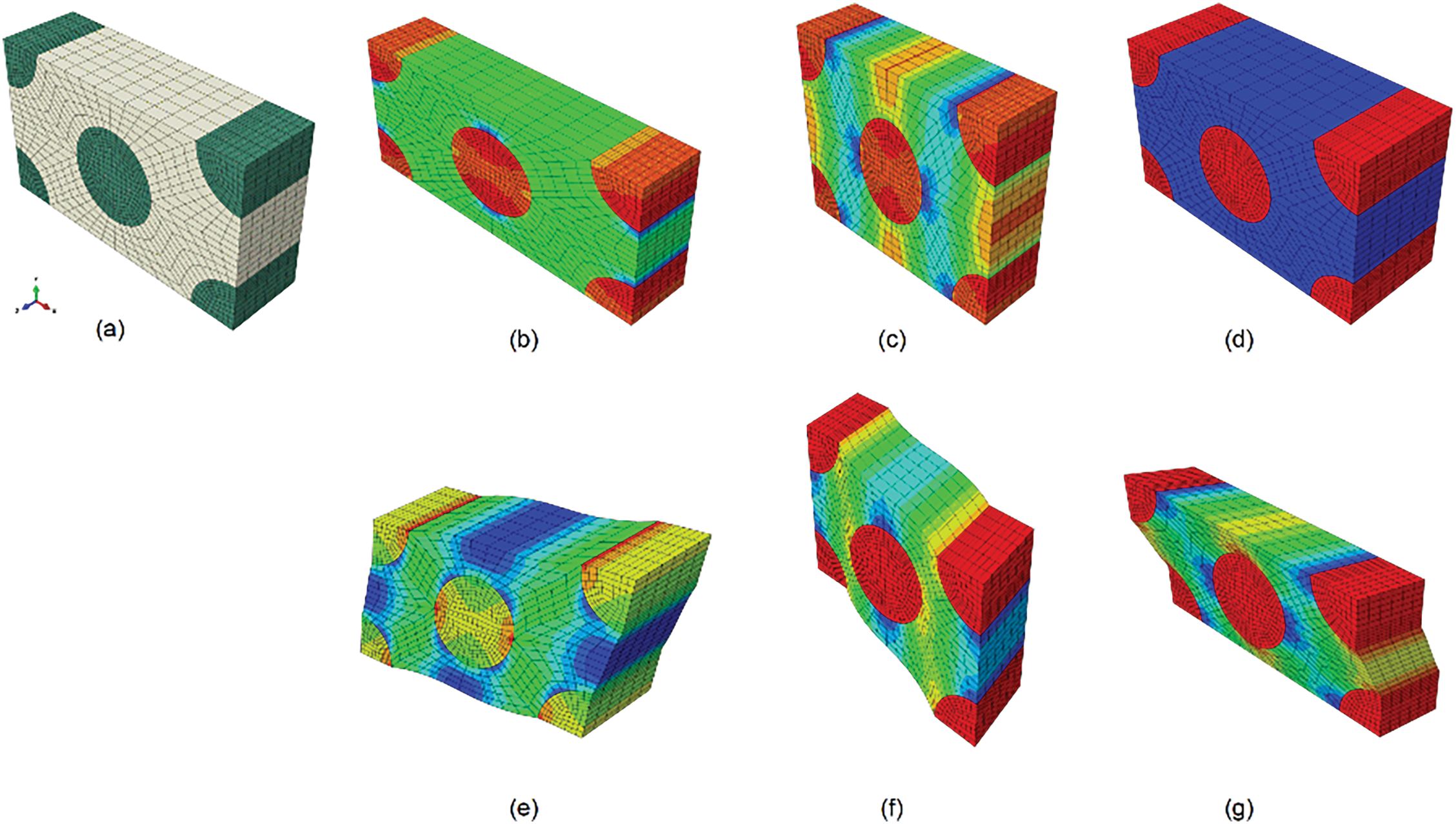
Figure 5: Demonstrations of DNS model and six loading cases: (a) Honeycomb unit cell; (b) uniaxial tension test in x-direction; (c) uniaxial tension test in y-direction; (d) uniaxial tension test in z-direction; (e) pure shear test in xy plane; (f) pure shear test in xz plane; (g) pure shear test in yz plane
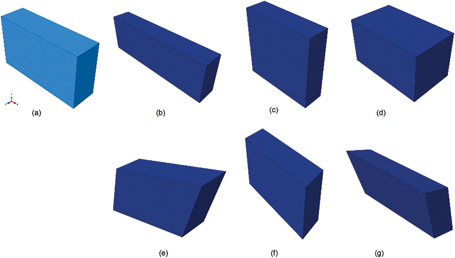
Figure 6: Demonstrations of homogenized model and six loading cases: (a) One-element model; (b) uniaxial tension test in x-direction; (c) uniaxial tension test in y-direction; (d) uniaxial tension test in z-direction; (e) pure shear test in xy plane; (f) pure shear test in xz plane; (g) pure shear test in yz plane
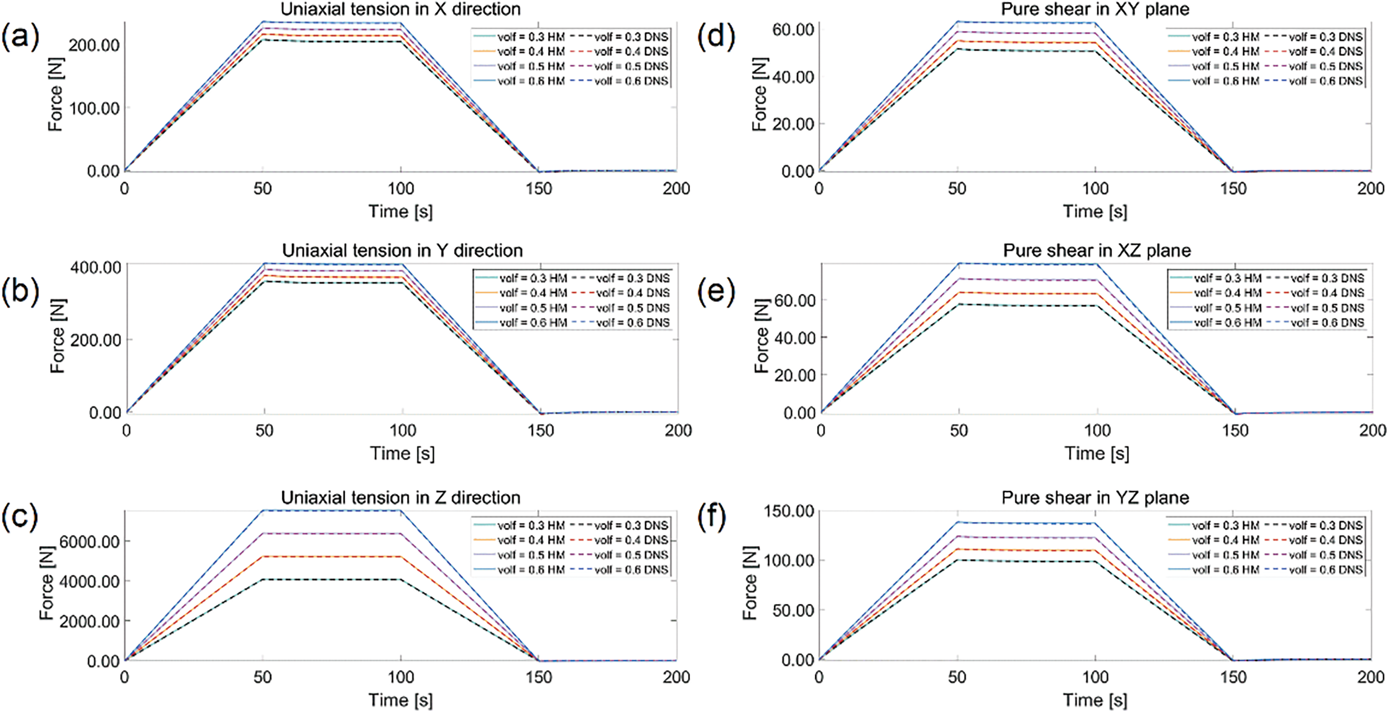
Figure 7: Relaxation curves under different fiber volume ratios with
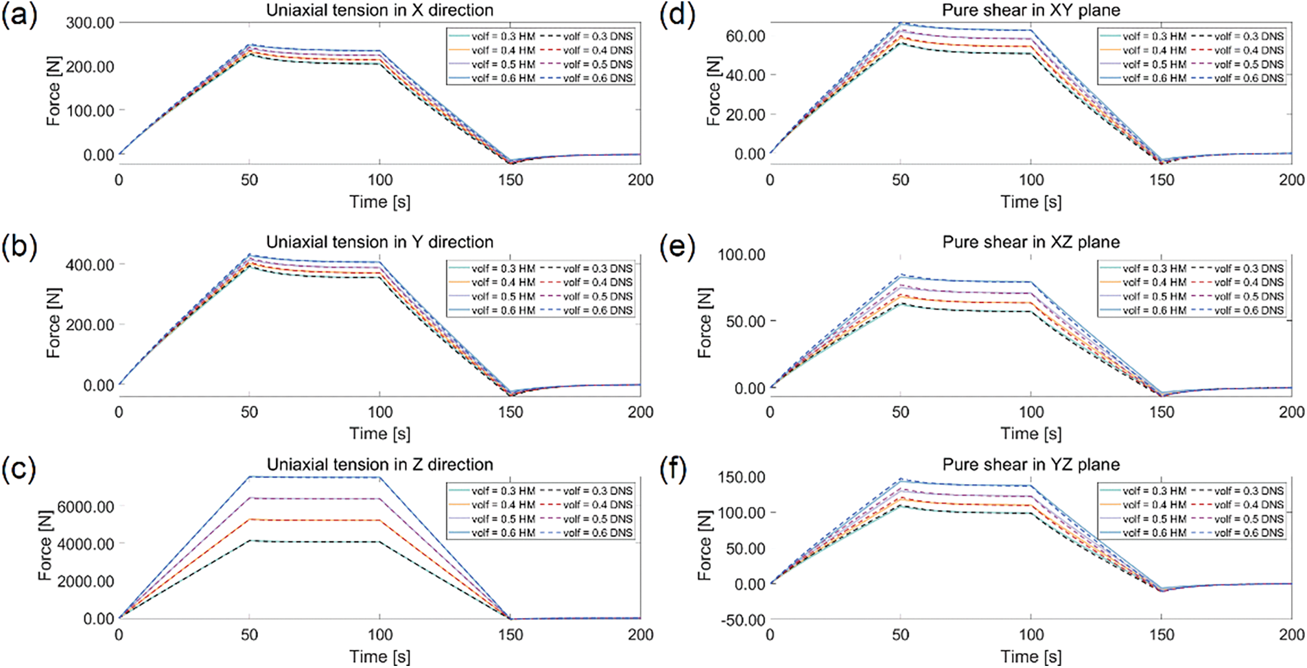
Figure 8: Relaxation curves under different fiber volume ratios with
The unit cell tests verify the homogenized viscoelastic model under uniform strain fields. To extend this validation to non-uniform strain fields, we propose a series of pure bending tests with geometric setups and boundary conditions outlined in Fig. 9. The size of beam is

Figure 9: Geometric setup of pure bending beam and boundary conditions
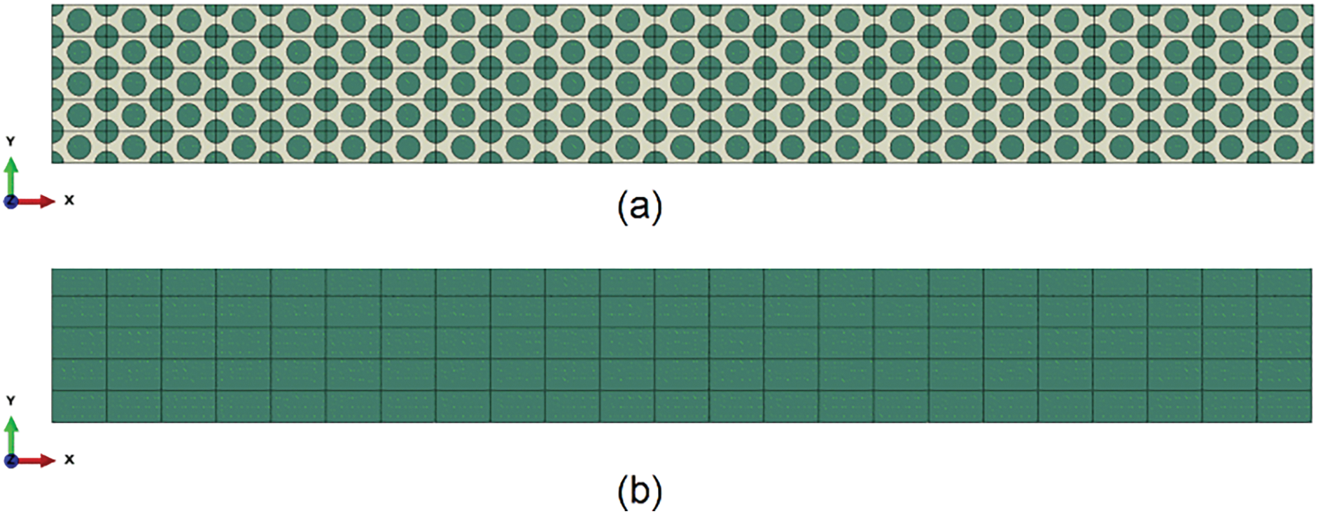
Figure 10: Pure bending beam models: (a) DNS; (b) homogenized model
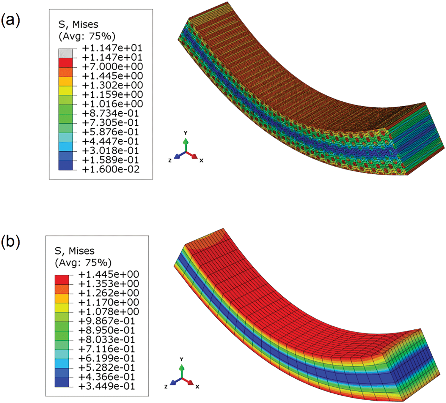
Figure 11: Pure bending beam simulation result demonstrations: (a) DNS; (b) homogenized model
We tested different fiber volume fractions,
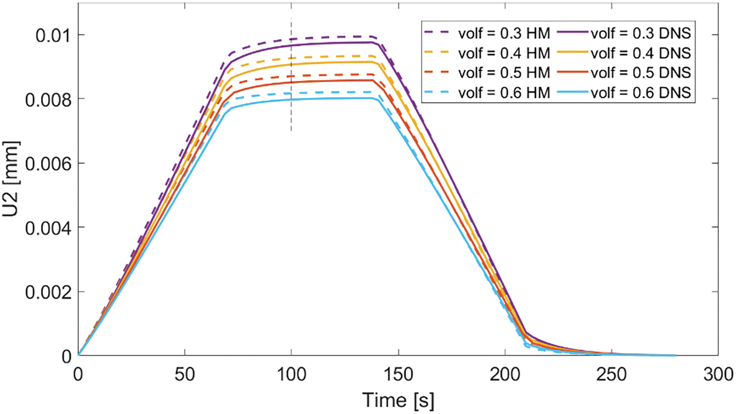
Figure 12: Pure bending beam experiment under different fiber volume fractions: DNS and homogenized model result comparison with
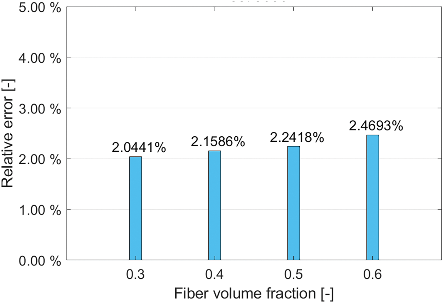
Figure 13: Pure bending beam tests under different fiber volume fractions: displacement relative error between DNS and homogenized model result with
In this section, the beam used for the pure bending tests is employed to conduct torsion tests. We select viscoelastic parameters as
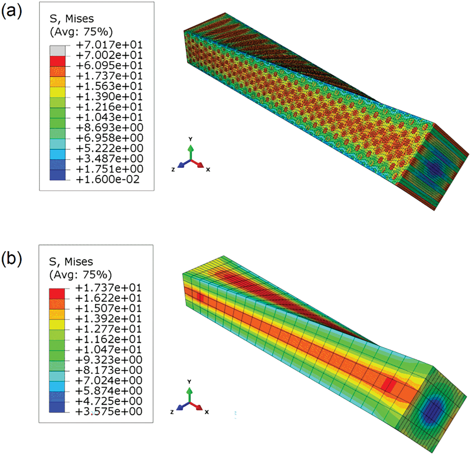
Figure 14: Beam torsion simulation result demonstrations: (a) DNS; (b) homogenized model
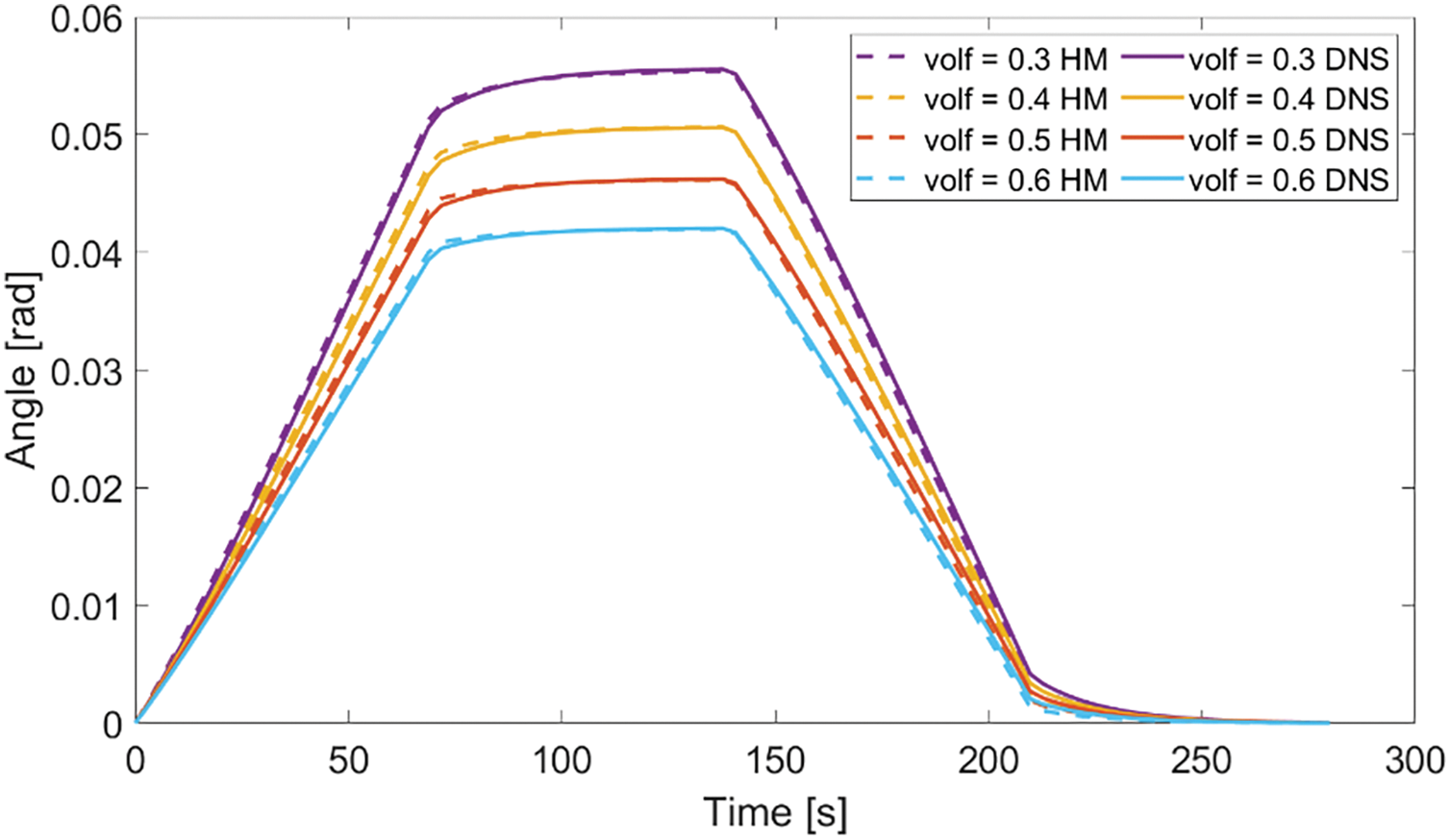
Figure 15: Beam torsion experiment under different fiber volume fractions, DNS and homogenized model result comparison with
We obtained experimental data from a paper published by Thiruppukuzhi et al. [52] and referenced another paper by Chen et al. [53]. In the first paper, Thiruppukuzhi et al. conducted experiments using S2-glass/8553-40 epoxy fiber-reinforced composite with a fiber volume fraction of


Figure 16: Setup of off-axial tensile tests
The elastic material parameters of both the fiber and matrix are identified inversely using experimental data of composite materials under two sets of conditions:

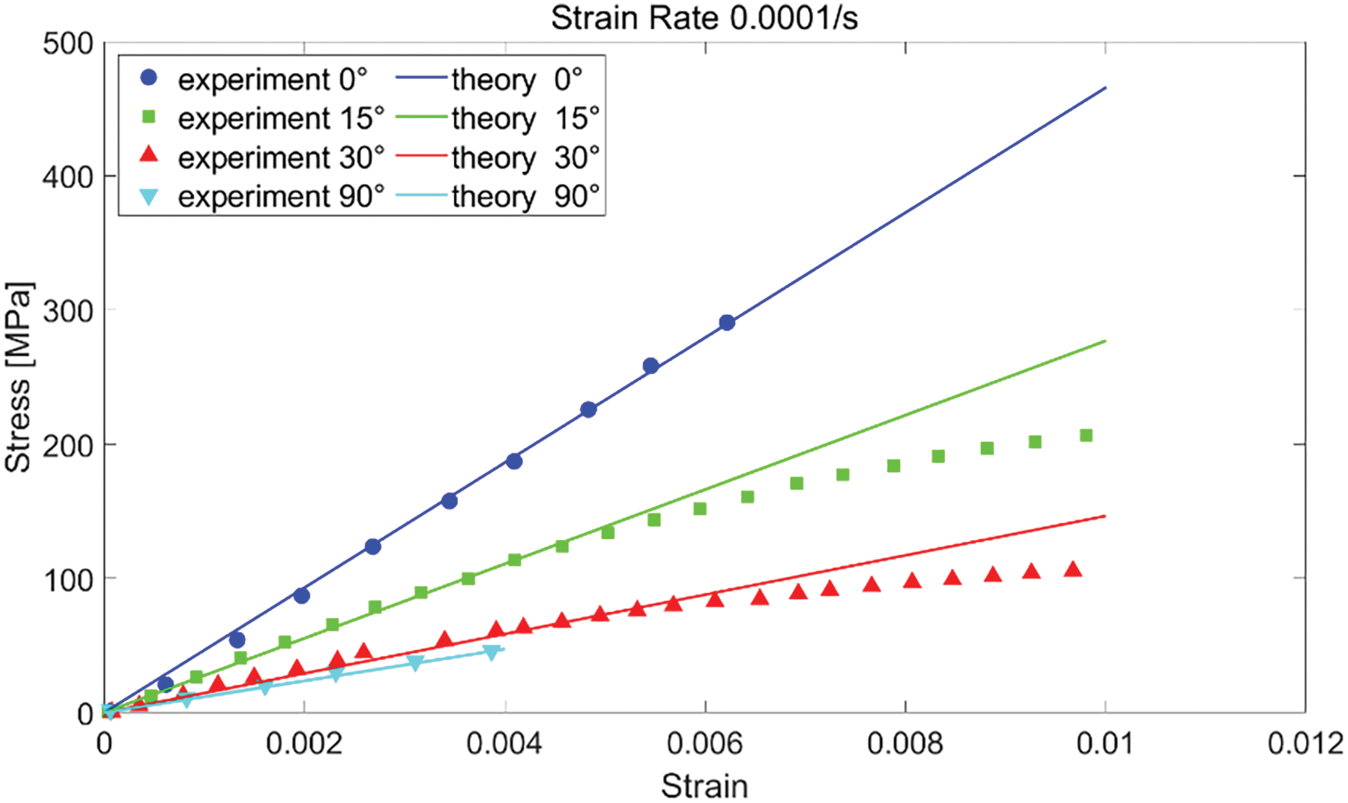
Figure 17: Strain-stress curves obtained from experiment results and homogenized model predictions for four off-axis tensile directions
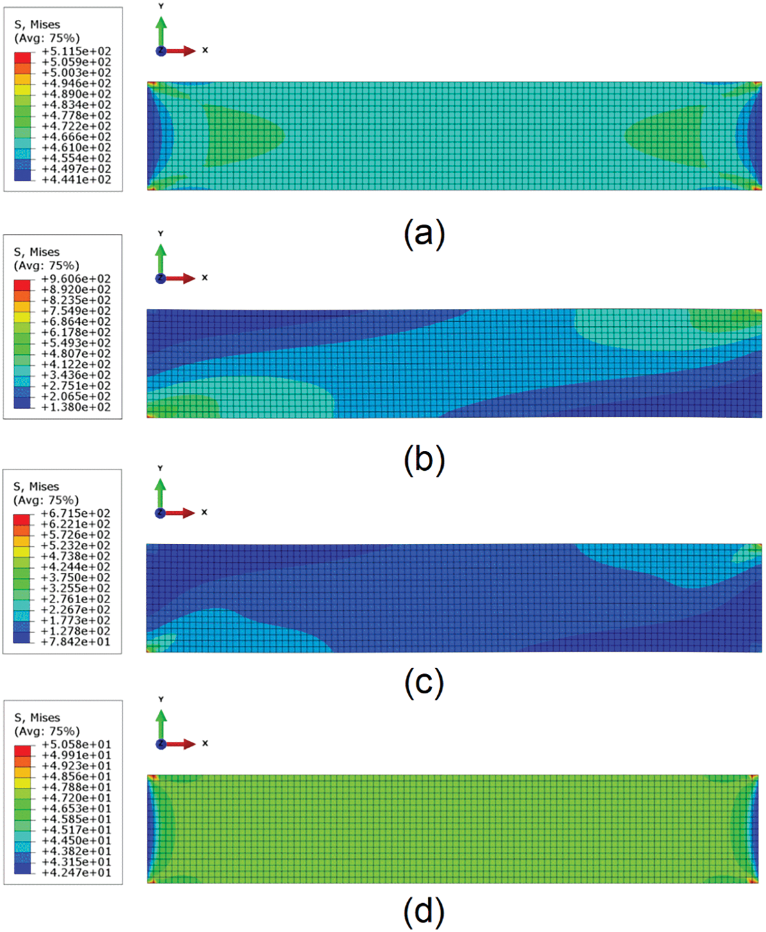
Figure 18: Von Mises stress cloud for homogenized models of four off-axis tensile directions: (a)
Figs. 19 and 20 present the homogenized model results and experimental data along directions
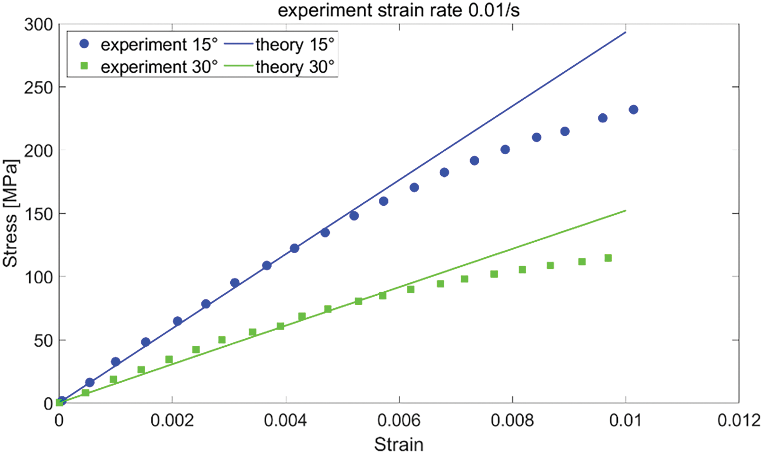
Figure 19: Strain-stress curves obtained from experiment results and homogenized model predictions for two off-axis tensile directions
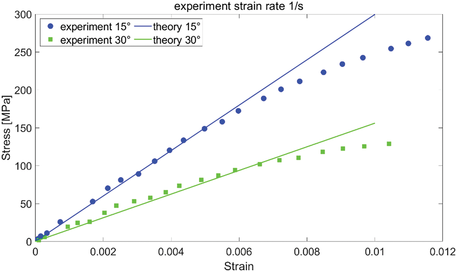
Figure 20: Strain-stress curves obtained from experiment results and homogenized model predictions for two off-axis tensile directions
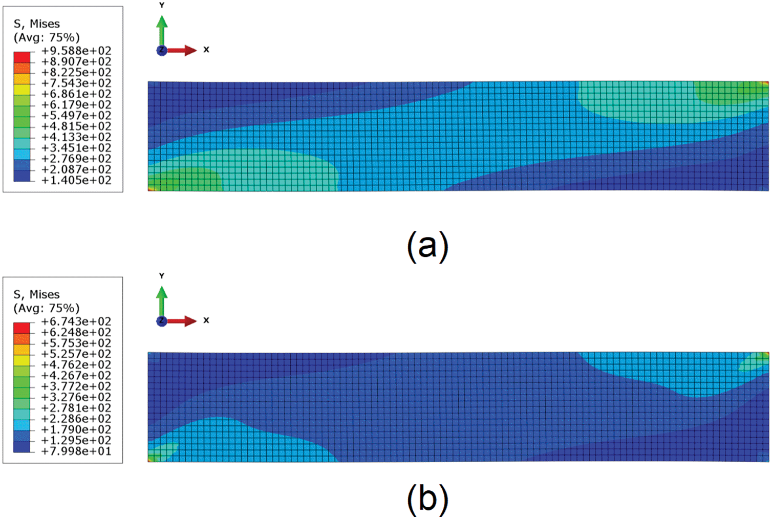
Figure 21: Von Mises stress contour plot for homogenized models of two off-axis tensile directions: (a)
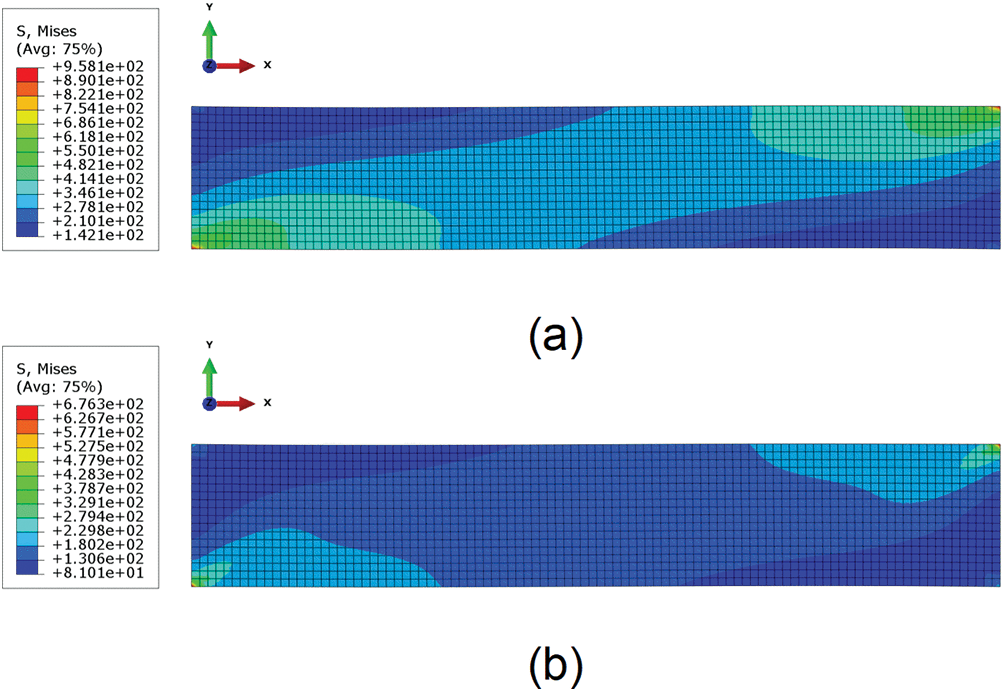
Figure 22: Von Mises stress contour plot for homogenized models of two off-axis tensile directions: (a)
In this manuscript, we propose an analytical homogenized viscoelastic model for fibrous composite materials using the reduced-order homogenization (ROH) method. Compared to numerical homogenization methods, our analytical model significantly reduces simulation costs while providing accurate predictions of the overall mechanical behavior. However, some deviations in local stress are observed, attributable to the one-partition-per-phase assumption. We model the fiber phase as transversely isotropic elastic, while the matrix phase follows a standard solid model. This approach allows for the analytical determination of effective moduli and relaxation times in fibrous composites. As the fiber volume fraction approaches zero, our homogenized viscoelastic model simplifies to a pure viscoelastic model. We verify our model through numerical unit cell tests, pure bending beam tests, and torsion tests, demonstrating its accuracy and computational efficiency compared to direct numerical simulations. Experimental validations further confirm the reliability of our approach.
Acknowledgement: The authors would like to acknowledge the support of the National Key R&D Program of China and the National Natural Science Foundation of China. The research is also supported by Peking University for this publication.
Funding Statement: Financial support by the National Key R&D Program of China (Grant No. 2023YFA1008901) and the National Natural Science Foundation of China (Grant Nos. 11988102, 12172009) is gratefully acknowledged. The research is also supported by “The Fundamental Research Funds for the Central Universities, Peking University”.
Author Contributions: The authors confirm contribution to the paper as follows: Huilin Jia contributed to the formula derivation, and simulation. Shanqiao Huang assisted in offering methodology and revising the manuscript. Zifeng Yuan contributed to the initial idea, the overall structure and final editing of the manuscript. All authors reviewed the results and approved the final version of the manuscript.
Availability of Data and Materials: Data available on request from the authors.
Ethics Approval: Not applicable.
Conflicts of Interest: The authors declare no conflicts of interest to report regarding the present study.
References
1. Z. Guo et al., “3D printing of curvilinear fiber reinforced variable stiffness composite structures: A review,” Compos. Part B Eng., vol. 272, no. 1, 2024, Art. no. 112039. doi: 10.1016/j.compositesb.2024.112039. [Google Scholar] [CrossRef]
2. P. Aduwenye, B. W. Chong, P. Gujar, and X. Shi, “Mechanical roperties and durability of carbon fiber reinforced cementitious composites: A review,” Constr. Build. Mater., vol. 452, 2024, Art. no. 138822. doi: 10.1016/j.conbuildmat.2024.138822. [Google Scholar] [CrossRef]
3. Z. Li, B. Wang, P. Hao, K. Du, Z. Mao and T. Li, “Multi-scale numerical calculations for the interphase mechanical properties of carbon fiber reinforced thermoplastic composites,” Compos. Sci. Technol., vol. 260, 2025, Art. no. 110982. doi: 10.1016/j.compscitech.2024.110982. [Google Scholar] [CrossRef]
4. M. Mohammed et al., “A review on the advancement of renewable natural fiber hybrid composites: Prospects, challenges, and industrial applications,” J. Renew. Mater., vol. 12, pp. 1237–1290, 2024. doi: 10.32604/jrm.2024.051201. [Google Scholar] [CrossRef]
5. H. Awais, Y. Nawab, A. Amjad, A. Anjang, H. M. Akil and M. S. Z. Abidin, “Environmental benign natural fibre reinforced thermoplastic composites: A review,” Compos. Part C Open Access, vol. 4, 2021, Art. no. 100082. doi: 10.1016/j.jcomc.2020.100082. [Google Scholar] [CrossRef]
6. B. Nedjar, “A time dependent model for unidirectional fibre-reinforced composites with viscoelastic matrices,” Int. J. Solids Struct., vol. 48, no. 16–17, pp. 2333–2339, 2011. doi: 10.1016/j.ijsolstr.2011.04.007. [Google Scholar] [CrossRef]
7. U. Hofer, M. Luger, R. Traxl, and R. Lackner, “Closed-form expressions for effective viscoelastic properties of fiber-reinforced composites considering fractional matrix behavior,” Mech. Mater., vol. 127, pp. 14–25, 2018. doi: 10.1016/j.mechmat.2018.08.005. [Google Scholar] [CrossRef]
8. Q. Chen, G. Chatzigeorgiou, and F. Meraghni, “Extended mean-field homogenization of viscoelastic-viscoplastic polymer composites undergoing hybrid progressive degradation induced by interface debonding and matrix ductile damage,” Int. J. Solids Struct., vol. 210–211, pp. 1–17, 2021. doi: 10.1016/j.ijsolstr.2020.11.017. [Google Scholar] [CrossRef]
9. C. A. Suarez-Afanador, N. Lahellec, and M. I. Idiart, “Mean-field descriptions for the viscoelastic response of thermorheologically complex reinforced solids,” Eur. J. Mech. A Solids, vol. 98, 2023, Art. no. 104859. doi: 10.1016/j.euromechsol.2022.104859. [Google Scholar] [CrossRef]
10. P. Lenz and R. Mahnken, “Multiscale simulation of polymer curing of composites combined mean-field homogenisation methods at large strains,” Int. J. Solids Struct., vol. 290, no. 2, 2024, Art. no. 112642. doi: 10.1016/j.ijsolstr.2023.112642. [Google Scholar] [CrossRef]
11. Q. Li, W. Chen, S. Liu, and J. Wang, “A novel implementation of asymptotic homogenization for viscoelastic composites with periodic microstructures,” Compos. Struct., vol. 208, no. 1–3, pp. 276–286, 2019. doi: 10.1016/j.compstruct.2018.09.056. [Google Scholar] [CrossRef]
12. Y. -M. Yi, S. -H. Park, and S. -K. Youn, “Asymptotic homogenization of viscoelastic composites with periodic microstructures,” Int. J. Solids Struct., vol. 35, no. 17, pp. 2039–2055, 1998. doi: 10.1016/S0020-7683(97)00166-2. [Google Scholar] [CrossRef]
13. I. V. Andrianov, V. V. Danishevs’kyy, and D. Weichert, “Homogenization of viscoelastic-matrix fibrous composites with square-lattice reinforcement,” Arch. Appl. Mech., vol. 81, no. 12, pp. 1903–1913, 2011. doi: 10.1007/s00419-011-0526-z. [Google Scholar] [CrossRef]
14. C. Badulescu, N. Lahellec, and P. Suquet, “Field statistics in linear viscoelastic composites and polycrystals,” Eur. J. Mech. A Solids, vol. 49, pp. 329–344, 2015. doi: 10.1016/j.euromechsol.2014.07.012. [Google Scholar] [CrossRef]
15. G. Debotton and L. Tevet-Deree, “The response of a fiber-reinforced composite with a viscoelastic matrix phase,” J. Compos. Mater., vol. 38, no. 14, pp. 1255–1277, 2004. doi: 10.1177/0021998304042732. [Google Scholar] [CrossRef]
16. K. Kowalczyk-Gajewska and H. Petryk, “Sequential linearization method for viscous/elastic heterogeneous materials,” Eur. J. Mech. A Solids, vol. 30, no. 5, pp. 650–664, 2011. doi: 10.1016/j.euromechsol.2011.04.002. [Google Scholar] [CrossRef]
17. R. Brenner, R. Masson, O. Castelnau, and A. Zaoui, “A quasi-elastic affine formulation for the homogenised behaviour of nonlinear viscoelastic polycrystals and composites,” Eur. J. Mech. A Solids, vol. 21, no. 6, pp. 943–960, 2002. doi: 10.1016/S0997-7538(02)01247-0. [Google Scholar] [CrossRef]
18. H. Zhai, T. Bai, Q. Wu, N. Yoshikawa, K. Xiong and C. Chen, “Time-domain asymptotic homogenization for linear-viscoelastic composites: Mathematical formulae and finite element implementation,” Compos. Part C Open Access, vol. 8, 2022, Art. no. 100248. doi: 10.1016/j.jcomc.2022.100248. [Google Scholar] [CrossRef]
19. Y. Liu, F. P. V. der Meer, L. J. Sluys, and J. T. Fan, “A numerical homogenization scheme used for derivation of a homogenized viscoelastic-viscoplastic model for the transverse response of fiber-reinforced polymer composites,” Compos. Struct., vol. 252, no. 1, 2020, Art. no. 112690. doi: 10.1016/j.compstruct.2020.112690. [Google Scholar] [CrossRef]
20. A. Carini, F. Genna, and F. Levi, “Time domain analytical bounds to the homogenized viscous kernels of linear viscoelastic composites,” Eur. J. Mech. A Solids, vol. 102, no. 6, 2023, Art. no. 105108. doi: 10.1016/j.euromechsol.2023.105108. [Google Scholar] [CrossRef]
21. C. Mareau, V. Favier, B. Weber, A. Galtier, and M. Berveiller, “Micromechanical modeling of the interactions between the microstructure and the dissipative deformation mechanisms in steels under cyclic loading,” Int. J. Plast., vol. 32–33, pp. 106–120, 2012. doi: 10.1016/j.ijplas.2011.12.004. [Google Scholar] [CrossRef]
22. M. Zecevic and M. Knezevic, “Latent hardening within the elasto-plastic self-consistent polycrystal homogenization to enable the prediction of anisotropy of AA6022-T4 sheets,” Int. J. Plast., vol. 105, pp. 141–163, 2018. doi: 10.1016/j.ijplas.2018.02.007. [Google Scholar] [CrossRef]
23. Y. Rémond, “Constitutive modelling of viscoelastic unloading of short glass fibre-reinforced polyethylene,” Compos. Sci. Technol., vol. 65, no. 3–4, pp. 421–428, 2005. doi: 10.1016/j.compscitech.2004.09.010. [Google Scholar] [CrossRef]
24. O. Pierard and I. Doghri, “Study of various estimates of the macroscopic tangent operator in the incremental homogenization of elastoplastic composites,” Int. J. Multiscale Comput. Eng., vol. 4, no. 4, pp. 521–543, 2006. doi: 10.1615/IntJMultCompEng.v4.i4.80. [Google Scholar] [CrossRef]
25. P. Suquet, “Overall properties of nonlinear composites: A modified secant moduli theory and its link with Ponte Castañeda’s nonlinear variational procedure,” Comptes Rendus Académie Sci. Sér. II Mécanique Phys. Chim. Astron., vol. 320, pp. 563–571, 1995. [Google Scholar]
26. C. Bleiler, P. P. Castañeda, and O. Röhrle, “Tangent second-order homogenisation estimates for incompressible hyperelastic composites with fibrous microstructures and anisotropic phases,” J. Mech. Phys. Solids, vol. 147, no. 4, 2021, Art. no. 104251. doi: 10.1016/j.jmps.2020.104251. [Google Scholar] [CrossRef]
27. M. Barral, G. Chatzigeorgiou, F. Meraghni, and R. Léon, “Homogenization using modified Mori-Tanaka and TFA framework for elastoplastic-viscoelastic-viscoplastic composites: Theory and numerical validation,” Int. J. Plast., vol. 127, no. 2–3, p. 102632, 2020. doi: 10.1016/j.ijplas.2019.11.011. [Google Scholar] [CrossRef]
28. G. J. Dvorak and Y. Benveniste, “On transformation strains and uniform fields in multiphase elastic media,” Proc. R Soc. Lond A, vol. 437, no. 1900, pp. 291–310, 1992. doi: 10.1098/rspa.1992.0062. [Google Scholar] [CrossRef]
29. J. C. Michel and P. Suquet, “Nonuniform transformation field analysis,” Int. J. Solids Struct., vol. 40, no. 25, pp. 6937–6955, 2003. doi: 10.1016/S0020-7683(03)00346-9. [Google Scholar] [CrossRef]
30. J. C. Michel and P. Suquet, “Computational analysis of nonlinear composite structures using the nonuniform transformation field analysis,” Comput. Methods Appl. Mech. Eng., vol. 193, no. 48–51, pp. 5477–5502, 2004. doi: 10.1016/j.cma.2003.12.071. [Google Scholar] [CrossRef]
31. J. Fish, V. Filonova, and Z. Yuan, “Hybrid impotent-incompatible eigenstrain based homogenization,” Int. J. Numer. Methods Eng., vol. 95, no. 1, pp. 1–32, 2013. doi: 10.1002/nme.4473. [Google Scholar] [CrossRef]
32. E. Sanchez-Palencia, Non-Homogeneous Media and Vibration Theory. Berlin, Heidelberg: Springer, 1980, vol. 127. doi: 10.1007/3-540-10000-8. [Google Scholar] [CrossRef]
33. G. Papanicolau, A. Bensoussan, and J. L. Lions, Asymptotic Analysis for Periodic Structures. New York, USA: Elsvier North-Holland, 1978. [Google Scholar]
34. Q. Yu and J. Fish, “Multiscale asymptotic homogenization for multiphysics problems with multiple spatial and temporal scales: A coupled thermo-viscoelastic example problem,” Int. J. Solids Struct., vol. 39, no. 26, pp. 6429–6452, 2002. doi: 10.1016/S0020-7683(02)00255-X. [Google Scholar] [CrossRef]
35. Y. Rahali, M. Assidi, I. Goda, A. Zghal, and J. F. Ganghoffer, “Computation of the effective mechanical properties including nonclassical moduli of 2.5D and 3D interlocks by micromechanical approaches,” Compos. Part B Eng., vol. 98, no. 10, pp. 194–212, 2016. doi: 10.1016/j.compositesb.2016.04.066. [Google Scholar] [CrossRef]
36. T. J. R. Hughes, J. A. Cottrell, and Y. Bazilevs, “Isogeometric analysis: CAD, finite elements, NURBS, exact geometry and mesh refinement,” Comput. Methods Appl. Mech. Eng., vol. 194, no. 39–41, pp. 4135–4195, 2005. doi: 10.1016/j.cma.2004.10.008. [Google Scholar] [CrossRef]
37. J. A. Cottrell, T. J. Hughes, and Y. Bazilevs, Isogeometric Analysis: Toward Integration of CAD and FEA. The Atrium, Southern Gate, Chichester, West Sussex, UK: John Wiley & Sons, 2009. [Google Scholar]
38. S. Matsubara, S. -N. Nishi, and K. Terada, “On the treatments of heterogeneities and periodic boundary conditions for isogeometric homogenization analysis,” Int. J. Numer. Methods Eng., vol. 109, no. 11, pp. 1523–1548, 2017. doi: 10.1002/nme.5328. [Google Scholar] [CrossRef]
39. R. Alberdi, G. Zhang, and K. Khandelwal, “A framework for implementation of RVE-based multiscale models in computational homogenization using isogeometric analysis,” Int. J. Numer. Methods Eng., vol. 114, no. 9, pp. 1018–1051, 2018. doi: 10.1002/nme.5775. [Google Scholar] [CrossRef]
40. F. Schmidt, M. Krüger, M. -A. Keip, and C. Hesch, “Computational homogenization of higher-order continua,” Int. J. Numer. Methods Eng., vol. 123, no. 11, pp. 2499–2529, 2022. doi: 10.1002/nme.6948. [Google Scholar] [CrossRef]
41. X. Du, Q. Chen, G. Chatzigeorgiou, F. Meraghni, G. Zhao and X. Chen, “Nitsche’s method enhanced isogeometric homogenization of unidirectional composites with cylindrically orthotropic carbon/graphite fibers,” Compos. Sci. Technol., vol. 256, no. 3, 2024, Art. no. 110787. doi: 10.1016/j.compscitech.2024.110787. [Google Scholar] [CrossRef]
42. Q. Chen, X. Du, W. Wang, G. Chatzigeorgiou, F. Meraghni and G. Zhao, “Isogeometric homogenization of viscoelastic polymer composites via correspondence principle,” Compos. Struct., vol. 323, 2023, Art. no. 117475. doi: 10.1016/j.compstruct.2023.117475. [Google Scholar] [CrossRef]
43. C. Oskay and J. Fish, “Eigendeformation-based reduced order homogenization for failure analysis of heterogeneous materials,” Comput. Methods Appl. Mech. Eng., vol. 196, no. 7, pp. 1216–1243, 2007. doi: 10.1016/j.cma.2006.08.015. [Google Scholar] [CrossRef]
44. J. Fish, Practical Multiscaling. The Atrium, Southern Gate, Chichester, West Sussex, UK: John Wiley & Sons, 2014. [Google Scholar]
45. J. Fish, K. Shek, M. Pandheeradi, and M. S. Shephard, “Computational plasticity for composite structures based on mathematical homogenization: Theory and practice,” Comput. Methods Appl. Mech. Eng., vol. 148, no. 1-2, pp. 53–73, 1997. doi: 10.1016/S0045-7825(97)00030-3. [Google Scholar] [CrossRef]
46. Z. Yuan and J. Fish, “Multiple scale eigendeformation-based reduced order homogenization,” Comput. Methods Appl. Mech. Eng., vol. 198, no. 21–26, pp. 2016–2038, 2009. doi: 10.1016/j.cma.2008.12.038. [Google Scholar] [CrossRef]
47. J. Fish, Z. Yang, and Z. Yuan, “A second-order reduced asymptotic homogenization approach for nonlinear periodic heterogeneous materials,” Int. J. Numer. Methods Eng., vol. 119, no. 6, pp. 469–489, 2019. doi: 10.1002/nme.6058. [Google Scholar] [CrossRef]
48. Z. Yang, Y. Liu, Y. Sun, Y. Jing, and Q. Ma, “A novel second-order reduced homogenization approach for nonlinear thermo-mechanical problems of axisymmetric structures with periodic micro-configurations,” Comput. Methods Appl. Mech. Eng., vol. 368, no. 3, 2020, Art. no. 113126. doi: 10.1016/j.cma.2020.113126. [Google Scholar] [CrossRef]
49. Z. Yang, Y. Sun, Y. Liu, and Q. Ma, “A second-order reduced multiscale approach for non-linear axisymmetric structures with periodic configurations,” Appl. Math. Model., vol. 88, no. 3, pp. 791–809, 2020. doi: 10.1016/j.apm.2020.07.009. [Google Scholar] [CrossRef]
50. J. C. Simo and T. J. Hughes, Computational Inelasticity. New York, USA: Springer Science & Business Media, 2006. [Google Scholar]
51. G. Dvorak, Micromechanics of Composite Materials. New York, USA: Springer Science & Business Media, 2012. [Google Scholar]
52. S. V. Thiruppukuzhi and C. T. Sun, “Models for the strain-rate-dependent behavior of polymer composites,” Compos Sci. Technol., vol. 61, no. 1, pp. 1–12, 2001. doi: 10.1016/S0266-3538(00)00133-0. [Google Scholar] [CrossRef]
53. Y. Chen, Z. Zhao, D. Li, Z. Guo, and L. Dong, “Constitutive modeling for linear viscoelastic fiber-reinforced composites,” Compos. Struct., vol. 263, 2021, Art. no. 113679. doi: 10.1016/j.compstruct.2021.113679. [Google Scholar] [CrossRef]
In this section, we solve the ODE equation system in Eq. (27) to obtain the matrix phase strains. With the reduced 1-index defined in Eq. (22), we can rewrite Eq. (27) into the following system of ODEs:
and
Here
For the coupled ODEs defined in Eq. (A1a), notice that
Define the following two strains:
and the corresponding ODEs become:
The solution of Eqs. (A5) can be written as
Substituting Eqs. (A6a) and (A6b) into (A4) yields the solution that
The shearing response Eqs. (A1b)–(A1d), can be solved similarly. Taking Eq. (A1b) as an example. Rewrite Eq. (A1b) into
so that the solution can be given by the convolution form:
Similarly, the solutions of (A1c) and (A1d) are written with convolution form that
respectively.
Cite This Article
 Copyright © 2025 The Author(s). Published by Tech Science Press.
This work is licensed under a Creative Commons Attribution 4.0 International License , which permits unrestricted use, distribution, and reproduction in any medium, provided the original work is properly cited.


 Submit a Paper
 Propose a Special lssue
 View Full Text
 Download PDF
 Downloads
 Citation Tools