 Open Access
ARTICLE
Analysis of Linear and Nonlinear Vibrations of Composite Rectangular Sandwich Plates with Lattice Cores
Faculty of Mechanical Engineering, Shahrood University of Technology, Shahrood, P.O. Box 3619995161, Iran
* Corresponding Author: Alireza Shaterzadeh. Email:
(This article belongs to the Special Issue: Multiscale and Multiphysics Computational Methods of Heterogeneous Materials and Structures)
Computers, Materials & Continua 2025, 82(1), 223-257. https://doi.org/10.32604/cmc.2024.059441
Received 08 October 2024; Accepted 27 November 2024; Issue published 03 January 2025
Abstract
For the first time, the linear and nonlinear vibrations of composite rectangular sandwich plates with various geometric patterns of lattice core have been analytically examined in this work. The plate comprises a lattice core located in the middle and several homogeneous orthotropic layers that are symmetrical relative to it. For this purpose, the partial differential equations of motion have been derived based on the first-order shear deformation theory, employing Hamilton’s principle and Von Kármán’s nonlinear displacement-strain relations. Then, the nonlinear partial differential equations of the plate are converted into a time-dependent nonlinear ordinary differential equation (Duffing equation) by applying the Galerkin method. From the solution of this equation, the natural frequencies are extracted. Then, to calculate the non-linear frequencies of the plate, the non-linear equation of the plate has been solved analytically using the method of multiple scales. Finally, the effect of some critical parameters of the system, such as the thickness, height, and different angles of the stiffeners on the linear and nonlinear frequencies, has been analyzed in detail. To confirm the solution method, the results of this research have been compared with the reported results in the literature and finite elements in ABAQUS, and a perfect match is observed. The results reveal that the geometry and configuration of core ribs strongly affect the natural frequencies of the plate.Keywords
Nomenclature
| Plate thickness, | |
| Core thickness, | |
| Rib thickness, | |
| Structure thickness, | |
| Displacements, | |
| Cartesian coordinates | |
| Dimensions of rectangular sandwich plate, | |
| Dimensions of a core element, | |
| Stiffener cross-section, | |
| The number of complete cells in the x-direction | |
| The number of complete cells in the y-direction | |
| Percentage of incomplete cell coefficient | |
| Moment resultants of stress components, | |
| Force resultants of stress components, | |
| K | Shear correction factor |
| Normal strain components | |
| Shear strain components | |
| Strain component along the length of the stiffener | |
| Strain component in the direction of the width of the stiffener | |
| Stress components, | |
| t | Time, sec |
| Young’s modulus of core, | |
| Young’s modulus of layers, | |
| Shear modulus of core, | |
| Shear modulus of layers, | |
| Second moment of mass per unit lateral area, | |
| Density, | |
| υ | Poisson’s ratio |
| ω | Frequency, |
| Nonlinear frequencies, | |
| Non-dimensional parameter |
During the last decades, the high demands in aerospace, marine, and automotive industries geared research to improve the mechanical properties of structures. Improvements are directed towards enhancing strength-to-weight ratio and stiffness-to-weight ratio, as well as energy absorption, corrosion, and moisture absorption resistance. Lattice composite structures have raised much attention concerning designers and engineers. Researchers have made significant strides in examining the dynamic responses of the lattice-reinforced and sandwich structures in vibrational analysis. Hemmatnezhad et al. [1] studied the vibration response of lattice-stiffened composite cylindrical shells by applying first-order shear deformation theory and compared their results with 3D ABAQUS simulations. Zhang et al. [2], based on the third-order shear deformation theory and Von Kármán type strain relations, developed nonlinear free vibration equations of anisogrid-core sandwich plates. Rahnama et al. [3] investigated the vibrational characteristics of lattice sandwich truncated conical shells and validated their theoretical models by ABAQUS simulations and experimental modal tests. Wu et al. [4] investigated the free vibration of the beams, having periodic lattice-truss cores, while applying Bernoulli-Euler and Timoshenko beam theories to optimize fundamental frequency and unit cell mass. Finally, Googolth et al. [5] conducted a numerical analysis of free vibration in thin rectangular plates using ANSYS, comparing their findings with exact Levy-type solutions for validation. In buckling analysis, extensive research has been conducted to understand the stability and load-bearing behavior of lattice and sandwich composite structures. Kidane et al. [6] proposed an analytical model for calculating the global buckling load of lattice-stiffened composite cylindrical shells; their findings were further advanced with experimental validation. Kanou et al. [7] investigated isogrid composite lattice cylindrical structures subjected to axial and pressure loads; some critical failure modes included are local rib and global buckling. Shatov et al. [8], using finite element analysis, conducted a study on the buckling of sandwich cylindrical shells with composite lattice cores subjected to hydrostatic pressure, giving special attention to the effect of spiral rib count and orientation on the buckling mode. Zarei et al. [9] have presented a smeared stiffener method for analyzing global buckling in the case of laminated sandwich conical shells with lattice cores. They confirm that this method is effective using the 3D finite element model. Shahgholian-Ghahfarokhi et al. [10,11] have applied the vibration correlation technique to predict buckling loads in both iso-grid core sandwich plates and axially loaded composite lattice sandwich cylinders structures, presenting experimental results showing less than 5% deviation. This research has significant practical implications, as it can be used to design more efficient and reliable structures. For instance, it can help design lightweight yet sturdy aerospace structures. In combined (analytical and numerical) methods, several researchers have advanced hybrid approaches for enhanced accuracy in the structural analysis of composite lattices. Wodesenbet et al. [12] improved the smeared method by modeling the buckling on an iso grid stiffened composite cylinder by assessing the contribution of the stiffeners and their validation against the comprehensive 3D finite element model. Totaro et al. [13] presented an analytical and numerical optimization technique for estimating minimum weight in composite lattice shell structures under axial compression. Their technique significantly reduced weight compared to conventional approaches. Researchers have explored innovative designs in lattice cores’ material and structural design to enhance vibration, buckling, and load response performance. Gholizadeh Eratbeni et al. [14] designed a lattice truss core glass fiber sandwich panel and investigated its vibration performance by experimental and numerical analysis, presenting good agreement among the results. Vasiliev et al. [15] presented, for the first time, the state-of-the-art anisogrid composite lattice structures, describing strength-to-weight efficiency, design procedures, and application experience in aerospace flight missions. Ramu et al. used finite element methods to analyze isotropic thin plates [16], and the results obtained were compared with exact solutions. It was found that there was a good correlation, and thus, the method’s reliability was verified. In the optimization and efficiency of vibrational performance, researchers such as Wang et al. [17] contributed much to optimizing the dynamic response characteristics of lattice sandwich plates. They used an improved (FSDT) and a hybrid Grey Wolf Optimization and Particle Swarm Optimization (GWO-PSO) algorithm, thus ensuring multi-objective optimization, this balanced high natural frequencies with a minimum value of displacement and mass. In advanced vibrational and structural analysis techniques, several researchers have employed innovative methods to enhance the accuracy and understanding of vibrational behavior in composite structures with lattice cores. Shahgholian Ghahfarkhi et al. [18] considered free vibration in composite sandwich cylindrical shells with lattice cores and detected natural frequencies much larger than that of no stiffened shells. Taati et al. [19–21] have proposed and validated a model to analyze nonlinear vibrations in sandwich plates comprising pyramidal truss cores on an elastic foundation. They studied the nonlinear vibrations of multilayered sandwich plates under fluid flow and proved that the new impermeability condition significantly affects pressure distribution. They further investigated the buckling and vibration of sandwich cylindrical shells subjected to external airflow, concluding that the piston theory is insufficient for very long, thin shells. Shahgholian-Ghahfarokhi et al. [22–24] proposed the buckling analytical models for composite shells with lattice cores by reducing the complicated geometry of the core to the equivalent solid forms for efficient analysis and further comparing with the finite element. Researchers like Amoozgar et al. [25] investigated the influence brought about by initial curvature and the shape of the lattice core on the vibrational characteristics of sandwich beams, and their results showed that core shape and density ratio are possible factors that will most highly affect dynamic behavior. Zhang et al. [26] studied nonlinear vibrations in lattice sandwich beams with pyramidal truss cores; the combined effects of the thermal environment, load, and core configuration on dynamic responses have been considered. Liu et al. [27] applied homogenization to the vibrational response of pyramid lattice sandwich plates, studying the parameters of the lattice core responsible for frequency and resonance. Further advancements include Chai et al. [28], who gave a theoretical framework for the vibrations in sandwich plates with pyramidal truss cores, investigating the influence of geometrical and material properties on the vibrational behavior. Yousefi et al. [29] presented a procedure to calculate the natural frequencies and mode shapes for laminated angle-ply plates, considering variable fiber orientation and lamination sequence. Phuong et al. [30] studied the nonlinear vibration and buckling of reinforced composite panels with inclined stiffeners under the influence of thermal environments. They further validated their analysis by comparing it with the Runge-Kutta analysis. Minfang et al. [31] investigated random vibration characteristics in lattice sandwich panels. The core parameters affect the most critical structural response metric, the displacement’s power spectral density (PSD).
Additionally, Hashemi et al. [32] examined the nonlinear vibrational characteristics of in-plane bidirectional functionally graded (IBFG) plates with temperature-dependent properties for the first time, which could be useful in studying resonance dynamics. For the first time, Li et al. [33] applied the Rayleigh-Ritz approach to the vibration analysis of plates with cutouts, obtaining greater computational efficiency using the independent coordinate coupling method (ICCM).
Qian et al. [34] applied the Meshless Local Petrov-Galerkin method to analyze three-dimensional electrodynamic deformations in rectangular plates by calculating transverse shear and normal deformations and validating the results. Finally, Nazari et al. [35] applied Meshless Local Petrov-Galerkin and artificial neural networks to conduct the natural frequency analysis of sandwich rectangular plates, changing the core-to-thickness ratio and volume fraction index.
Limited studies have been done on the vibration behavior of composite sandwich structures with lattice cores and their construction, especially regarding the effects of various core angles, stiffener density, and complex geometries on rectangular sandwich plates. This study investigates four core models, introducing models (a) and (c) with newly calculated stiffness matrices. These models have been analyzed for the first time. Meanwhile, models (b) and (d) represent anisogrid and isogrid structures. Also, the values of models (b) and (c) stiffness matrices are equal, and their geometric forms differ. Linear and nonlinear frequencies are determined by calculating stiffness matrices for different geometric patterns of the core based on first-order shear deformation theory and the equivalent stiffness method.
Using Hamilton’s principle, equations of motion for the nonlinear case are derived, and the Galerkin method is applied to convert these into a time-dependent Duffing equation. In the last step, linear and non-linear frequencies with simply supported boundary conditions were extracted by solving the linear state of the Duffing equation and using the multiple scale method for the non-linear state of the Duffing equation, respectively. Finally, the effect of key parameters of the system, such as the thickness, height, and different angles of the stiffeners on the natural frequencies, have been analyzed in detail. Due to the lack of sufficient resources to compare the data directly, the results of this research have been compared with studies that used the Levy solution method. Due to the boundary conditions and relative simplicity, Levy’s method is one of the valid methods for analyzing rectangular plates with simply supported boundary conditions. However, the Galerkin method has more advantages than the Levy method, including greater flexibility in modeling complex geometries, higher accuracy in solving differential equations using high-order polynomials, and better performance in parallel computations. Also, Levy’s method has limitations in certain boundary conditions that Galerkin’s method is free from, such as wholly closed or free edges on all sides, which cannot solve these boundary conditions. Also, model (a) results with an angle of 30 degrees and the number of divisions (N/2 = 10) are compared with the results of finite element analysis in ABAQUS software and show good accuracy.
Fig. 1 shows a composite rectangular sandwich plate composed of a lattice composite core with different geometric patterns. The plate is made of a lattice core located in the middle and several homogeneous orthotropic layers that are symmetrical relative to it. Besides, the fiber direction of layers, except for the core, have a phase difference angle of 90 degrees relative to each other. The direction of the coordinate axes is shown in the Fig. 1.
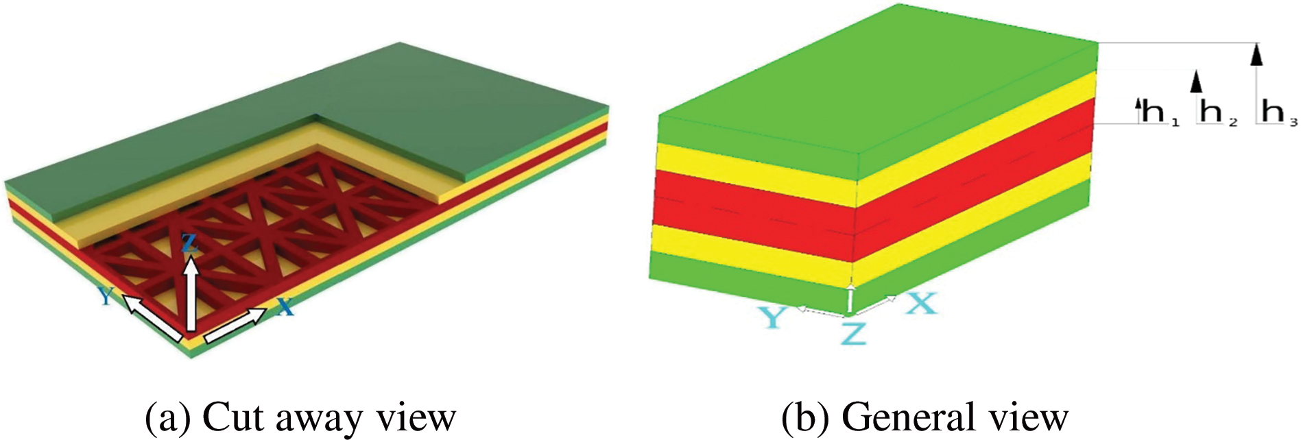
Figure 1: Rectangular sandwich plate with lattice core
Fig. 2 displays the geometry and configuration of the various patterns of lattice stiffeners. Four models of lattice stiffeners are considered according to Fig. 2. Figs. 1 and 2 were drawn using CATIA and Inventor software.
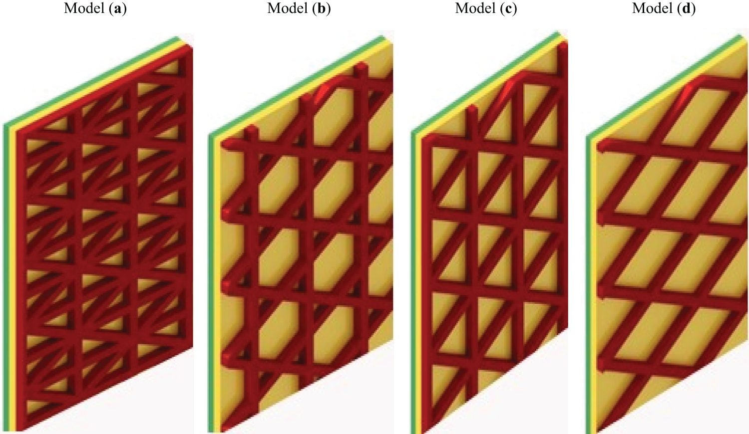
Figure 2: Various patterns of lattice stiffeners
In Fig. 2a, first, an analytical model for calculating the angular stiffness force of stiffeners is presented. Then the same procedure is repeated for the stiffeners of the other three models. A unit cell is considered the same in the four models to compare the longitudinal and transverse dimensions. Also, the angles of cross ribs in the first model
To obtain the analytical model, it is first necessary to introduce a unit cell of the reinforcing sandwich plate. The unit cell is selected in such a way that by repeating it, the whole lattice structure can be produced from a reinforcing shape. To obtain the stiffness matrix components, equivalent stiffness components to this unit cell can be obtained and extended to the whole model of the reinforced sandwich plate because the whole lattice structure is obtained from the repetition of a unit cell. To calculate the contribution of stiffeners to the total stiffness of the reinforced sandwich plate, the confrontation of the force and moment between the sandwich plate and the stiffeners should be analyzed. Then the stiffness matrices of the whole reinforced sandwich plate by overlapping the stiffness components of the sandwich plate and the stiffeners based on the volume ratio of each obtained. Due to finding the equivalent matrices A, B, and D of the sandwich plate and stiffeners, the compatibility equations should be a function of the strains and curvatures of the middle plate of the sandwich plate. In reinforcing strips, due to their small cross-section against the longitudinal section, the transverse modulus of the stiffener strips vs. the longitudinal modulus is omitted. Therefore here, it is assumed that the ribs can only withstand the axial force. Also, the following hypotheses should be considered in this analytical modeling:
1. The modulus of tensile elasticity of stiffeners in the direction perpendicular to the ribs should be much less than their longitudinal modulus. Also, the Transverse section dimensions of stiffeners are selected very small compared to their longitudinal dimensions so that it can be assumed that the stiffeners can withstand only axial force.
2. The strain is the same across the cross-section of the stiffeners and as a result, the stress is distributed evenly across the cross-section.
3. The force of action and reaction between the sandwich plate and the stiffeners is of shear force.
2.2 Force Analysis in a Unit Cell
The strains and curvatures of the middle plate of the sandwich plate, respectively, by
where
where in this regard,
with axial strains of stiffeners, the axial forces acting on each unit cell are easy to calculate. The force exerted on each rib is obtained from Eq. (4) according to Fig. 3, which shows one of the single cells of the model (a), with length
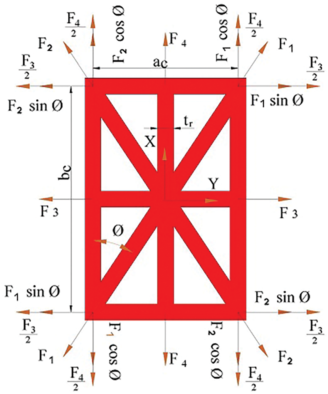
Figure 3: Forces diagram on a unit cell
By summing up the forces obtained in the directions x, y according to Eq. (5) and placing Eqs. (1) and (4) in them, the sum of the forces acting on the stiffeners in the x, y directions according to Eq. (6) is obtained.
Also, by dividing these forces on their corresponding edge in the unit cell, the results of the force according to Eq. (7a) for model (a) are obtained.
As can be seen, the values
2.3 Moment Analysis in a Unit Cell
The shear force between the plate and stiffeners generates moments. These moments are equal to the force multiplied by half the thickness of the plate and rib. Fig. 4 shows how these moments are generated by shear force

Figure 4: Moments created by the shear force between the plate and the stiffener
Fig. 5 shows, one of the single cells of model (a), with length
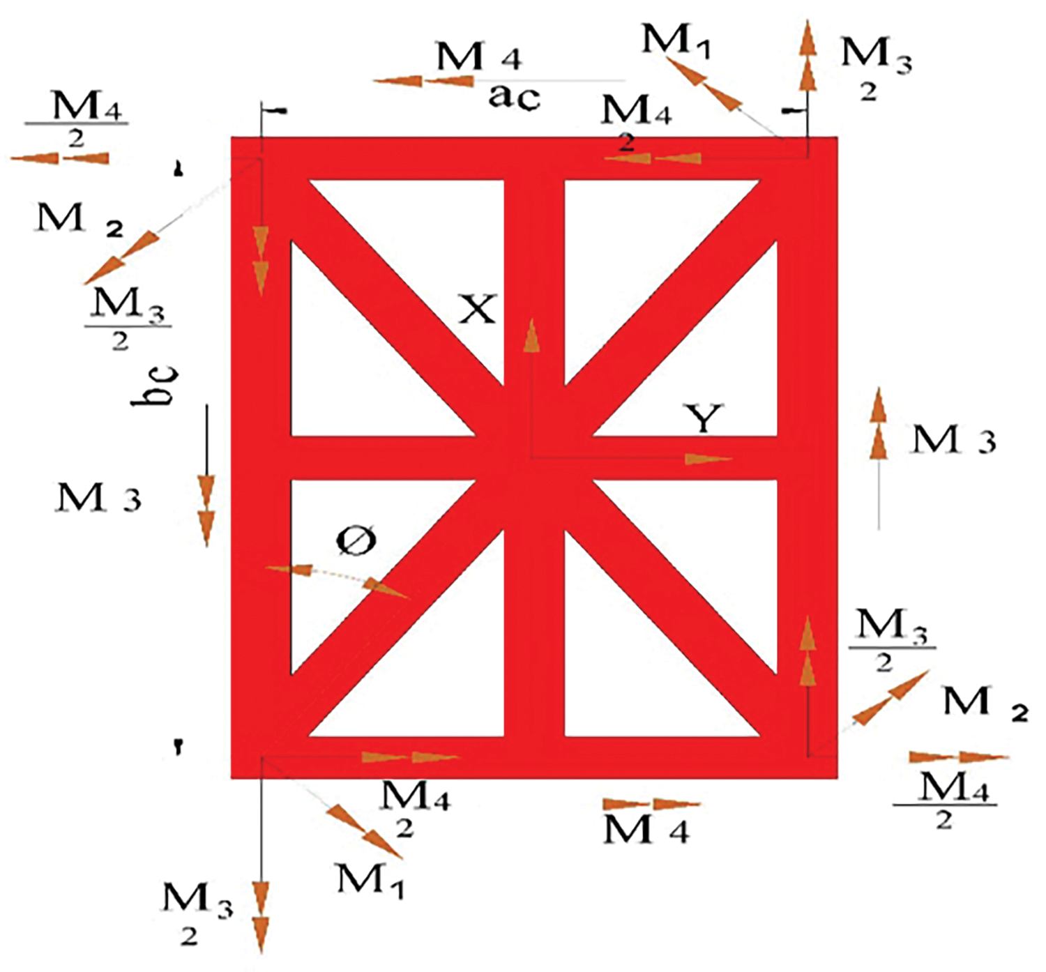
Figure 5: Moments diagram on a unit cell
In this regard,
2.4 Reinforcing Stiffness Matrix
Eqs. (7a) and (9) show the effect of reinforcing force and moment on the stiffened core sandwich plate, respectively. These equations are shown as a matrix in Eq. (10). superscript ‘S’ indicates the force and moment caused by the stiffener of the core. The components of the force and moment matrices are functions of the mid-plane strain and curvatures obtained from the analysis of the reinforcement force and moment.
In Eq. (10), the coefficient matrix is introduced by the reinforcement stiffness matrix
At first glance, the stiffness matrix resulting from Eq. (11) seems asymmetric. For example, the values of
Also, diagrams of force and moment for models
The geometric schematic of the structure with length a, width b, and height h consists of a few orthotropic layers. The middle layer is a lattice composite layer that is assumed to be orthotropic, and the remaining layers are orthotropic, too. On the other hand, in reinforcing strips, due to their small cross-section against the longitudinal section, the transverse modulus of the stiffener strips vs. the longitudinal modulus is omitted. Therefore, it is assumed that the ribs can only withstand the axial force. For this reason, the middle layer isotropic is considered. Meanwhile, the distribution of matter is symmetrical according to Fig. 1. Based on the first shear deformation theory, the components of the displacement field
where in Eq. (12), the components
The Von Kármán nonlinearity strains displacement relations by assuming large deformations are expressed as follows:
It is necessary to explain that the geometry studied in this research consists of four orthotropic layers and an isotropic core, which are symmetrical concerning the core. Also, the fibers of the first layer have a phase difference of 90-degrees compared to the second layer. Therefore, the equations of the plate have been extracted for one layer. These equations have been used according to the limits of integration and applying the variables of each layer.
The governing equations based on the first-order shear deformation theory are extracted from Eq. (14) using the principal Hamilton as follows:
where
By substituting Eq. (15) in Eq. (14) and integrating along the thickness the result is as follows:
where
where K is the shear stress correction factor and its amount is equal to 5/6.
The stress-strain relations based on the first- shear deformation theory is given as follows:
where stiffness coefficients
To derive the
Therefore, the core
By eradicating
The equations of motion (23) can be expressed in terms of displacements
Due to the orthotropic nature of the geometric model, the following assumptions have been considered in the plate motion equations.
Also, for being small of these variables
The admissible functions which the boundary conditions of Eq. (25) satisfied are given as follows:
where m and n are half-wave numbers, considering just one expression in the Eq. (26) and then substituting them in Eq. (24) and exerting the Galerkin method results in the time-dependent nonlinear differential equations of motion after using dimensionless parameters and mathematical simplifications can be earned as follows:
where
Now by writing a four-equation system between the Eqs. (27a), (27b), (27d), and (27e) and writing them in terms of w(t), putting them inside the Eq. (27c), it leads to a nonlinear time-dependent equation as follows:
Also, the coefficients of Eq. (28) are presented in Appendix (A6). For simplification, a set of dimensionless parameters is proposed as follows:
The non-dimensional form of Eq. (28) is extracted as follows:
According to relations (1) to (11) for extracting the stiffness matrix of the core are used. Also, from relations (21) and (22), the Q matrix components of layers and core are obtained, respectively. Meanwhile, according to the fundamental equations of a rectangular sandwich plate based on Eq. (24) and using the Galerkin method and the form of simply supported modes according to Eq. (26) and writing an integral relation in the direction of thickness, based on the data of the Table 1, nonlinear Duffing Eq. (28) is obtained. It is necessary to explain that the relative density of the core is used in the core relations. This density is obtained from the product of the core density in the ratio of the stiffener’s total cross-sectional area according to Eq. (31c) to the plate’s cross-sectional area (0.5

Also, the rest of the formulas for the cross-sectional area of the ribs models (d), (c), and (b) in Appendix (A7) are mentioned. Therefore, it is enough to apply their cross-sectional area values in Eq. (31c) to obtain the relative density of the rest of the models. In addition, these formulas are based on model (d).
The material properties of the different layers of the sandwich plate studied in this research are as described in Table 1.
Therefore, the linear frequencies are obtained according to the Duffing Eq. (30), and the non-linear frequencies are obtained using the method of multiple scales as follows.
The multiple-scales method is an analytical technique designed to construct accurate approximations for perturbation problems by introducing fast and slow scale variables. This approach eliminates terms that cause divergence in solutions, such as secular terms in the undamped Duffing equation, resulting in more stable outcomes [37,38]. In this paper, the method is applied analytically, utilizing precise formulations to accurately solve boundary conditions and nonlinear equations, thereby removing the need for numerical methods at this stage. Additionally, the nonlinear frequencies obtained from the multiple-scales method are directly proportional to the maximum amplitude of the nonlinear system, providing an accurate reflection of the system’s behavior under nonlinearity.
In this method, the response is modeled as a function of several independent variables instead of a single variable. Then, new independent variables are as follows:
It follows that the partial derivatives of
It is assumed that the solution of Eq. (30) can be displayed by an expansion having the form as follows:
Here the problem is solved with the order of the third order. Therefore, by placing Eqs. (33) and (34b) inside the Eq. (34a) and equating the coefficients, the following relationships are obtained.
Now, the first to third-order equations that need to be solved are as follows:
At first, the first-order equation is solved. After writing the private solution and removing the secular factor of the equation, its solution is inserted into the solution of the second-order equation. Again, after writing the private solution of the second-order equation and removing its secular factor, the private solutions of the first and second-order equations are placed in the third-order equation and solved. Finally, the final and private solutions of these equations are as follows, from order third to first:
By placing Eq. (37) inside Eq. (34b), converting the obtained relation into trigonometric form, separating the orders (1) to (3) and placing Eq. (32) in it, and simplifying the non-linear frequency relation can be obtained as follows:
In the first part, a comparative analysis of the results obtained from existing findings in the relevant field is conducted. In the second part, model (a) results under the angle of 30 degrees and the number of divisions of 10 per unit area have been compared with the data obtained from the finite element model in ABAQUS software. The new results extracted from this research are presented in the third part.
In this section, to evaluate the validity and efficiency of the current formulation, the results of this study are compared with the data of previously published works. Free vibration analysis of a rectangular sandwich plate with a lattice core is performed using the Galerkin method for simply supported boundary conditions with different thicknesses. The extracted results for the first six natural frequencies of a rectangular sandwich plate without considering the lattice core with a length of a = 0.6 and a width of b = 0.5 m and different thicknesses are shown in Table 2. It can be seen that the natural frequencies listed in this table show strong agreement with the findings reported in [5,16]. Given the limited resources for direct data comparison, this study’s results were validated against prior research that employed the Levy solution, which is suitable for rectangular plates with simply supported boundary conditions. However, the Galerkin method provides distinct advantages over the Levy approach, including greater flexibility for modeling complex geometries, higher accuracy in solving differential equations through high-order polynomials, and superior efficiency in parallel computations for similar problems. Additionally, while Levy’s method encounters limitations with specific boundary conditions, such as fully clamped or free edges on all sides, the Galerkin method operates without these restrictions, making it more versatile for a range of boundary conditions.

In addition to the previous comparison example, another example for a multi-layered plate consisting of orthotropic materials with geometric specifications of length 1, width 0.5, and height 0.003 m, for each layer according to References [29,39], and without considering the lattice core, has been considered and solved. The analytical method presented in this research was used. The results of this rectangular and symmetrical four-layer plate with a height of 0.012 m are presented with the previously reported results (based on the formula of orthotropic materials and classical theory) according to Table 3, which have high accuracy and convergence.

5.2 Validation of Results with Finite Element Method
In this research, due to the lack of a suitable model to compare the extracted results, one of the models (model (a)) has been analyzed under the angle of 30 degrees, and the number of divisions per unit area of (N/2 = 10) in ABAQUS software. The vibrational mode shapes of a sandwich plate with a lattice core depict the deformation patterns of the structure at different frequencies. This analysis provides insight into the structural response under simply supported boundary conditions for each specific mode. Precise modeling of these mode shapes is crucial for evaluating the contribution of the lattice core to the plate’s overall stability and performance. Fig. 6 presents selected mode shapes of the sandwich plate for model (a), highlighting these deformation patterns.
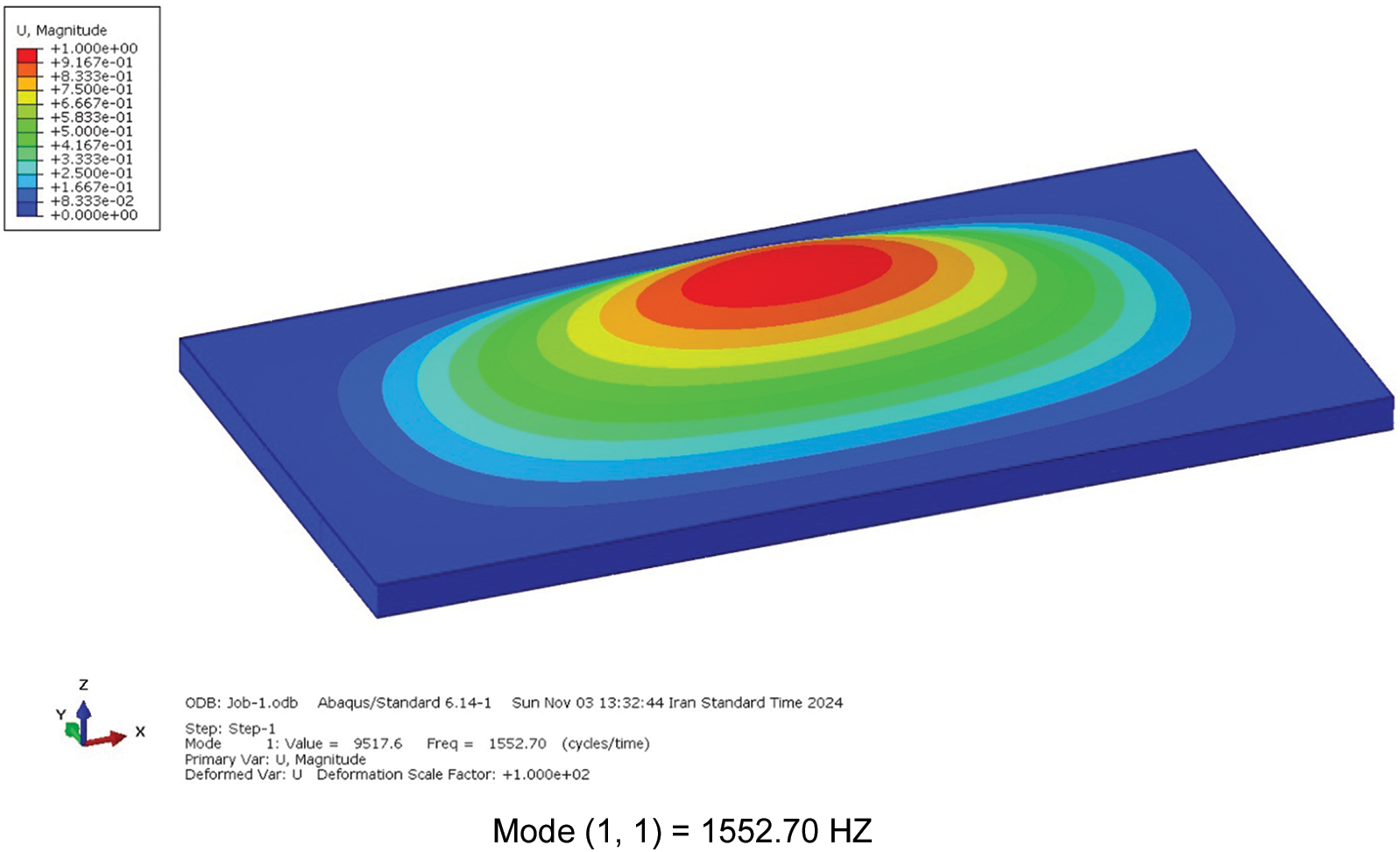

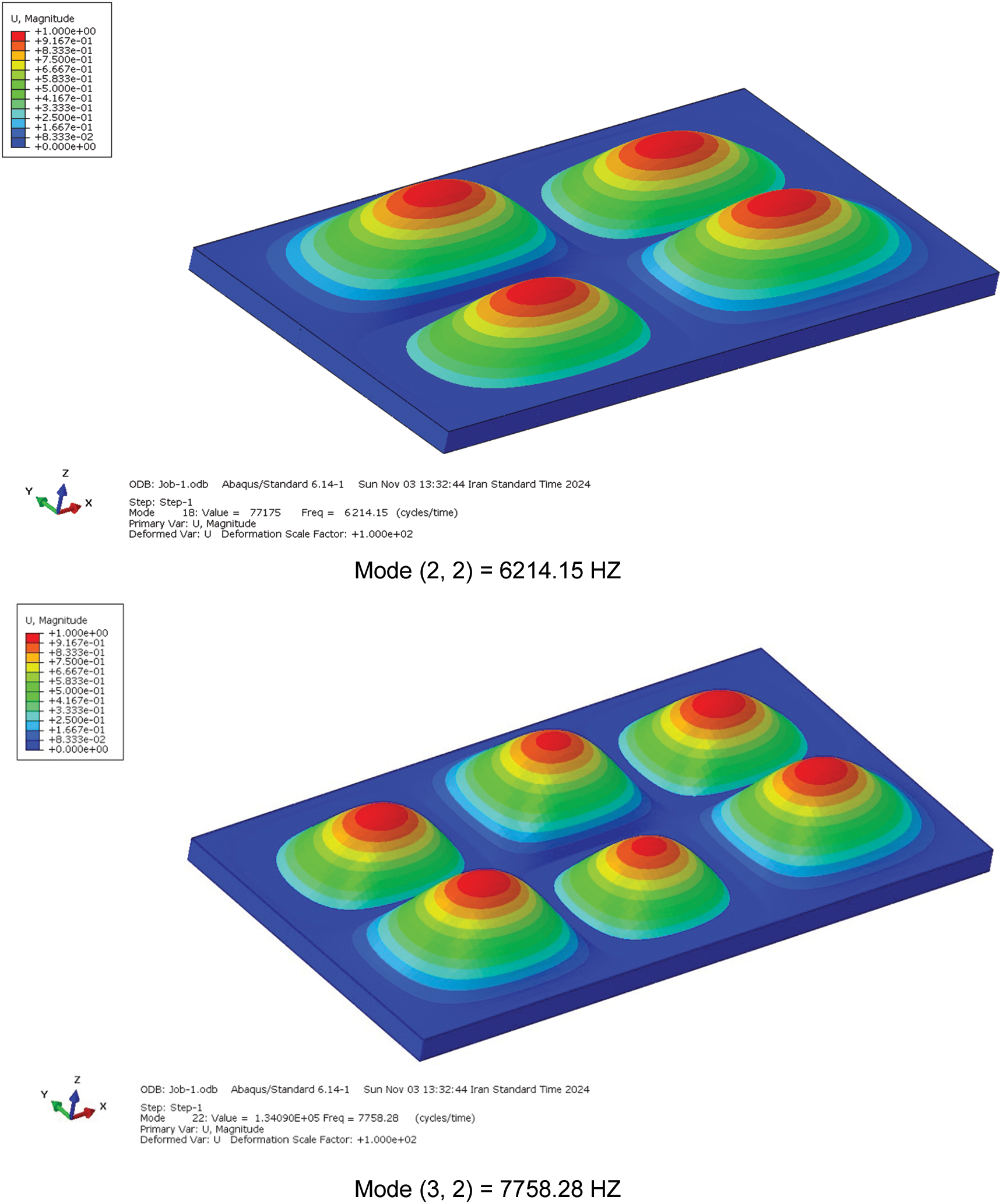
Figure 6: Six mode shapes for model (a) with an angle of 30 degrees and the number of divisions (N/2 = 10)
The finite element analysis was performed in ABAQUS using S4R shell elements with a mesh count of 50,041. In this study, the mode shapes derived from the analytical method for a rectangular plate with a lattice core (model (a)) and

5.3 Extracted Results for the Proposed Problem
This paper specifies a rectangular sandwich plate consisting of four layers, a lattice core, and different geometric patterns. This plate has a length of 1 m and a width of 0.5 m. The fibers of the layers have 90-degree symmetry to each other, and the layers themselves are symmetrical to the core. The simply supported boundary conditions are shown in Fig. 1. The specifications of the layers and the core in Table 1 and their other geometrical parameters are as follows:
The thickness of each layer is 0.003 m, and the thickness of the core is 0.02 m. The width of the ribs is 0.01 and 0.005 m. Also, the thickness of the investigated ribs in all Tables 5, 6, 7, 8, and 9 is 0.01 m, except for Table 5, where the thickness of the ribs is 0.005 m. So, the height of the sandwich plate used in this research is 0.032 m.


Utilizing the ratio obtained from Eq. (31c) to determine the cross-sectional area of the core ribs, this area is subsequently divided by the surface area of the plate (1 × 0.5 m²) and multiplied by the core density (1580 kg/m³). The relative density of the core for various geometry models has been evaluated for two configurations, with the number of ribs along the length of the plate being (N/2 = 10 and 6). These values for various models are presented in Tables 5–9.
Then the six linear and nonlinear primary frequencies of a rectangular sandwich plate with a lattice core and four various geometry patterns are presented under the names of model (a), model (b), model (c), and model (d), according to the results of Tables 5–9, which are reported as follows: Based on Tables 5 and 6, model (a) has been studied with ribs with thicknesses of 0.01 and 0.005 m, respectively.
According to Table 5, the following conclusions can be drawn:
Increasing the number of plate divisions (N/2) enhances the model’s accuracy, bringing it closer to reality. This improvement is evident when comparing linear and non-linear frequencies in the table. Moreover, as the model’s density decreases, the frequencies generally increase.
In most cases, there is minimal disparity between linear and non-linear frequencies, suggesting predominantly linear behavior across most modes.
The slight differences observed in specific modes (e.g., at a 60° angle and mode (1,2)) may stem from geometric or material nonlinear effects, which become apparent in more detailed simulations.
Altering the angle from 30° to 60° reveals noticeable frequency changes, highlighting the angle’s significant influence on the system’s natural frequencies.
For instance, at a 60-degree angle, the frequency of mode (1,1) surpasses that of the same mode at a 30-degree angle, possibly due to variations in system stiffness.
By observing the data in Table 6 and comparing it with Table 5, in addition to the previous results, it can also be concluded that reducing the thickness of the ribs from 0.01 to 0.005 m results in a lighter geometric model and higher geometric frequencies.
Free vibration analysis of a rectangular sandwich plate with lattice core model (b) is performed using the Galerkin method for simply supported boundary conditions with a total height of 0.032 m. The extracted results for the first six natural frequencies of a rectangular sandwich plate considering the lattice core with length a = 1 m and width b = 0.5 m and the thickness of core ribs 0.01 m and the number of plate divisions (N/2) are shown in Table 7. Therefore, in Tables 7–9, various models (b), (c), and (d) have been examined with the same conditions, respectively.
The data in Table 7 clearly demonstrate that reducing the number of plate divisions in this model decreases its density, making it lighter and increasing its frequencies. Additionally, as the angle increases from 30° to 60°, the frequencies generally rise, highlighting the significant impact of angle variations on frequencies. Moreover, the nonlinear effects of modal frequencies are notable, underscoring the importance of using this data for a better understanding and study of the dynamic behavior of similar structures.
Upon reviewing the data in Table 8, similar results to those in Table 7 are observed. Despite having the same stiffness matrix, the different geometric configurations between models (b) and (c) lead to distinct outcomes. Specifically, model (b) exhibits superior performance compared to model (c). For instance, at a 60-degree angle, the frequency value for mode (1,1) is 1829.63 for model (b), whereas it is 1793.18 for model (c).
Based on the preceding tables, Table 9 shows that by decreasing the number of plate divisions, the density of the plate decreases. Hence, both linear and nonlinear frequencies are increased within the model. Also, by increasing the angle, the modal frequencies increase. In addition, nonlinear frequencies are higher than the linear ones. That means nonlinear effects exist but their influences are very little on the values of the frequency. Hence, knowledge of those effects is important to make correct dynamic analysis and design for such a structure.
This study analytically examines a rectangular sandwich plate’s linear and nonlinear vibration analysis with a lattice core featuring various geometric patterns and simply supported boundary conditions. Using the Von Kármán nonlinearity strain-displacement relations, the partial differential equations of motion are derived based on FSDT and Hamilton’s principle. The nonlinear partial differential equations of motion are transformed into time-dependent nonlinear ordinary differential equations by applying the Galerkin procedure. Subsequently, the linear frequencies are determined using the Duffing equation, and the nonlinear frequencies of the rectangular sandwich plate are extracted with the aid of the multiple-scales method.
To validate the results, a simplified version of the problem without the core is first solved. The obtained results are compared with previously reported data for isotropic and orthotropic materials in Tables 2 and 3, respectively, demonstrating good agreement and accuracy. Meanwhile, model a’s results with an angle of 30 degrees and the number of divisions (N/2 = 10) are compared with the results of finite element analysis in ABAQUS software according to Table 4, and they show good accuracy. Additionally, various results of this study are presented in Tables 5–9. The following conclusions can be drawn from this investigation.
The following observations can be made from the tables by the results obtained:
1. In all four models, the natural frequencies of the structure are increased by increasing the angle between the ribs.
2. Within the four studied models, increasing the number of ribs on the core surface decreases the structure’s natural frequencies at angles of 30 and 45 degrees. Table 5 does not show this trend for mode numbers of (1,2) and (2,2) at an angle of 60 degrees.
3. In all the studied geometric models, maximum frequencies were related to model (b), and the minimum frequency belonged to model (a).
4. Decreasing the core ribs’ thickness has increased the structure’s natural frequencies.
5. The order of the maximum frequency between the four models considering four different angles each is given as:
6. The order of the value of maximum frequency among all four models, considering the angles, is:
7. The frequency difference is more significant for all models’ higher modes. In addition, the frequencies increase with increasing density.
8. The data in the tables indicate how mechanical modal frequencies can be affected by nonlinear factors and become even more pronounced when the angle and plate segmentation change is considered. Typically, one can see a slight variation between linear frequencies and their nonlinear versions, meaning that most modes respond linearly. However, there can be some, such as mode (1,2) at an angle of 60 degrees, which displays a range of observed responses that may be attributed to geometry or material nonlinearities. These observations play an essential role in understanding such structures’ dynamics. In other words, modifications of the natural frequencies by specific parameters are achieved, and these parameters should be incorporated into the design and analysis of the structures.
9. According to Table 4, the analytical method’s results are comparable to the finite element analysis in ABAQUS, which suggests that the technique used in this research is accurate.
Acknowledgement: The authors are grateful to the highly respected editor and reviewers for their valuable suggestions for improving the article.
Funding Statement: The authors received no specific funding for this study.
Author Contributions: Alireza Moradi contributed to the conceptualization, methodology, validation, investigation, and writing of original drafts and provided software. Alireza Shaterzadeh contributed to conceptualization, methodology, supervision, and writing review and editing. All authors reviewed the results and approved the final version of the manuscript.
Availability of Data and Materials: Data will be made available on reasonable request.
Ethics Approval: Not applicable.
Conflicts of Interest: The authors declare no conflicts of interest to report regarding the present study.
References
1. M. Hemmatnezhad, G. H. Rahimi, and R. Ansari, “On the free vibrations of grid-stiffened composite cylindrical shells,” Acta Mech., vol. 225, no. 2, pp. 609–623, 2014. doi: 10.1007/s00707-013-0976-1. [Google Scholar] [CrossRef]
2. D. Zhang, Y. Wang, G. Pan, and A. Hozuri, “Nonlinear free vibration modeling of anisogrid lattice sandwich plates based on a weak formulation analysis,” Commun. Nonlinear Sci. Numer. Simul., vol. 123, 2023, Art. no. 107277. doi: 10.1016/j.cnsns.2023.107277. [Google Scholar] [CrossRef]
3. M. Rahnama, S. R. Hamzeloo, and M. Morad Sheikhi, “Vibration analysis of anisogrid composite lattice sandwich truncated conical shells: Theoretical and experimental approaches,” J. Compos. Mater., vol. 58, no. 22, pp. 2429–2442, 2024. doi: 10.1177/00219983241264364. [Google Scholar] [CrossRef]
4. Z. Wu, J. Wu, F. Lu, C. Zhang, Z. Liu and Y. Zhu, “Free vibration analysis and multi-objective optimization of lattice sandwich beams,” Mech. Adv. Mater. Struct., vol. 31, no. 17, pp. 4037–4050, 2024. doi: 10.1080/15376494.2023.2189333. [Google Scholar] [CrossRef]
5. G. N. Guguloth, B. N. Singh, and V. Ranjan, “Free vibration analysis of simply supported rectangular plates,” Vibroeng. Proced., vol. 29, pp. 270–273, 2019. doi: 10.21595/vp.2019.21135. [Google Scholar] [CrossRef]
6. S. Kidane, G. Li, J. Helms, S. S. Pang, and E. Woldesenbet, “Buckling load analysis of grid stiffened composite cylinders,” Compos. B Eng., vol. 34, no. 1, pp. 1–9, 2003. doi: 10.1016/S1359-8368(02)00074-4. [Google Scholar] [CrossRef]
7. H. Kanou, S. M. Nabavi, and J. E. Jam, “Numerical modeling of stresses and buckling loads of isogrid lattice composite structure cylinders,” Int. J. Eng. Sci. Technol., vol. 5, no. 1, pp. 42–54, 2013. doi: 10.4314/ijest.v5i1.4. [Google Scholar] [CrossRef]
8. A. V. Shatov, A. E. Burov, and A. V. Lopatin, “Buckling of composite sandwich cylindrical shell with lattice anisogrid core under hydrostatic pressure,” J. Phys. Conf. Ser., vol. 1546, no. 1, 2020, Art. no. 012139. doi: 10.1088/1742-6596/1546/1/0121392. [Google Scholar] [CrossRef]
9. M. Zarei, G. H. Rahimi, and M. Hemmatnezhad, “Global buckling analysis of laminated sandwich conical shells with reinforced lattice cores based on the first-order shear deformation theory,” Int. J. Mech. Sci., vol. 187, 2020, Art. no. 105872. doi: 10.1016/j.ijmecsci.2020.105872. [Google Scholar] [CrossRef]
10. D. Shahgholian-Ghahfarokhi, M. Aghaei-Ruzbahani, and G. Rahimi, “Vibration correlation technique for the buckling load prediction of composite sandwich plates with iso-grid cores,” Thin-Walled Struct., vol. 142, pp. 392–404, 2019. doi: 10.1016/j.tws.2019.04.027. [Google Scholar] [CrossRef]
11. D. Shahgholian-Ghahfarokhi, G. Rahimi, G. Liaghat, R. Degenhardt, and F. Franzoni, “Buckling prediction of composite lattice sandwich cylinders (CLSC) through the vibration correlation technique (VCTNumerical assessment with experimental and analytical verification,” Compos. B Eng., vol. 199, no. 2, 2020, Art. no. 108252. doi: 10.1016/j.compositesb.2020.108252. [Google Scholar] [CrossRef]
12. E. Wodesenbet, S. Kidane, and S. S. Pang, “Optimization for buckling loads of grid stiffened composite panels,” Compos. Struct., vol. 60, no. 2, pp. 159–169, 2003. doi: 10.1016/S0263-8223(02)00315-X. [Google Scholar] [CrossRef]
13. G. Totaro and Z. Gürdal, “Optimal design of composite lattice shell structures for aerospace applications,” Aerosp. Sci. Technol., vol. 13, no. 4–5, pp. 157–164, 2009. doi: 10.1016/j.ast.2008.09.001. [Google Scholar] [CrossRef]
14. M. Gholizadeh Eratbeni, Y. Rostamiyan, and S. M. Seyyedi, “An experimental and numerical study on the vibration characteristics of glass fiber composite sandwich panel with lattice cores,” Proc. Inst. Mech. Eng. L J Mater. Des. Appl., vol. 236, no. 8, pp. 1604–1613, 2022. doi: 10.1177/14644207221075895. [Google Scholar] [CrossRef]
15. V. V. Vasiliev, V. A. Barynin, and A. F. Razin, “Anisogrid composite lattice structures-development and aerospace applications,” Compos. Struct., vol. 94, no. 3, pp. 1117–1127, 2012. doi: 10.1016/j.compstruct.2011.10.023. [Google Scholar] [CrossRef]
16. I. Ramu and S. C. Mohanty, “Study on free vibration analysis of rectangular plate structures using finite element method,” Procedia Eng., vol. 38, pp. 2758–2766, 2012. doi: 10.1016/j.proeng.2012.06.323. [Google Scholar] [CrossRef]
17. H. Wang, K. Liu, and M. Li, “Static bending, free vibration responses and multi-objective optimization of pyramidal lattice sandwich plates,” Int. J. Struct. Stab. Dyn., 2024, Art. no. 2550222. doi: 10.1142/S0219455425502220. [Google Scholar] [CrossRef]
18. D. Shahgholian-Ghahfarokhi, G. Rahimi, M. Zarei, and H. Salehipour, “Free vibration analyses of composite sandwich cylindrical shells with grid cores: Experimental study and numerical simulation,” Mech. Based Des. Struct. Mach., vol. 50, no. 2, pp. 687–706, 2022. doi: 10.1080/15397734.2020.1725565. [Google Scholar] [CrossRef]
19. E. Taati, F. Fallah, and M. T. Ahmadian, “On nonlinear free vibration of externally compressible fluid-loaded sandwich cylindrical shells: Curvature nonlinearity in bending and impermeability condition,” Thin-Walled Struct., vol. 179, 2022, Art. no. 109599. doi: 10.1016/j.tws.2022.109599. [Google Scholar] [CrossRef]
20. E. Taati, V. Rastian, and F. Fallah, “Nonlinear geometric fluid-structure interaction model of multilayered sandwich plates in contact with unbounded or bounded fluid flow,” Ocean Eng., vol. 292, 2024, Art. no. 116559. doi: 10.1016/j.oceaneng.2023.116559. [Google Scholar] [CrossRef]
21. E. Taati, “Aeroelasticity analysis of anisogrid lattice sandwich cylindrical shells: Extended potential and piston theories,” Mech. Adv. Mat. Struct., pp. 1–13, 2024. doi: 10.1080/15376494.2024.2329801. [Google Scholar] [CrossRef]
22. D. Shahgholian-Ghahfarokhi and G. Rahimi, “Buckling analysis of composite lattice sandwich shells under uniaxial compression based on the effective analytical equivalent approach,” Compos. B Eng., vol. 174, 2019, Art. no. 106932. doi: 10.1016/j.compositesb.2019.106932. [Google Scholar] [CrossRef]
23. D. Shahgholian-Ghahfarokhi and G. Rahimi, “An analytical approach for global buckling of composite sandwich cylindrical shells with lattice cores,” Int. J. Solids Struct., vol. 146, pp. 69–79, 2018. doi: 10.1016/j.ijsolstr.2018.03.021. [Google Scholar] [CrossRef]
24. D. Shahgholian-Ghahfarokhi and G. Rahimi, “New analytical approach for buckling of composite sandwich pipes with iso-grid core under uniform external lateral pressure,” J Sandwich Struct. Mater., vol. 23, no. 1, pp. 65–93, 2021. doi: 10.1177/1099636218821397. [Google Scholar] [CrossRef]
25. M. Amoozgar, S. A. Fazelzadeh, E. Ghavanloo, and R. M. Ajaj, “Free vibration analysis of curved lattice sandwich beams,” Mech. Adv. Mater. Struct., vol. 31, no. 2, pp. 343–355, 2024. doi: 10.1080/15376494.2022.2114043. [Google Scholar] [CrossRef]
26. W. Zhang, C. Wang, Y. Wang, J. J. Mao, and Y. Liu, “Nonlinear vibration responses of lattice sandwich beams with FGM face sheets based on an improved thermo-mechanical equivalent model,” Structures, vol. 44, pp. 920–932, 2022. doi: 10.1016/j.istruc.2022.08.052. [Google Scholar] [CrossRef]
27. R. Liu, Y. Zhong, Z. Shi, X. Liu, and J. Chen, “Free and forced vibration analysis of pyramid lattice sandwich plate based on the dimensional reduction model,” Thin-Walled Struct., vol. 174, 2022, Art. no. 109155. doi: 10.1016/j.tws.2022.109155. [Google Scholar] [CrossRef]
28. Y. Chai, S. Du, F. Li, and C. Zhang, “Vibration characteristics of simply supported pyramidal lattice sandwich plates on elastic foundation: Theory and experiments,” Thin-Walled Struct., vol. 166, 2021, Art. no. 108116. doi: 10.1016/j.tws.2021.108116. [Google Scholar] [CrossRef]
29. P. Yousefi, M. H. Kargarnovin, and S. H. Hosseini-Hashemi, “Free vibration of generally laminated plates with various shapes,” Polym. Compos., vol. 32, no. 3, pp. 445–454, 2011. doi: 10.1002/pc.21063. [Google Scholar] [CrossRef]
30. N. T. Phuong, V. M. Duc, N. T. Giang, L. N. Ly, N. T. T. Xuan and V. H. Nam, “Nonlinear vibration and dynamic buckling of complex curved functionally graded graphene panels reinforced with inclined stiffeners,” Int. J. Struct. Stab. Dyn., 2023, Art. no. 2450223. doi: 10.1142/S0219455424502237. [Google Scholar] [CrossRef]
31. M. F. Chen, Y. F. Zhong, J. Shi, and H. W. Cao, “Free and random vibration analyses of hourglass lattice sandwich panel using an equivalent model based on variational asymptotic method,” Thin-Walled Struct., vol. 189, 2023, Art. no. 110891. doi: 10.1016/j.tws.2023.110891. [Google Scholar] [CrossRef]
32. S. Hashemi and A. A. Jafari, “Nonlinear free and forced vibrations of in-plane bi-directional functionally graded rectangular plate with temperature-dependent properties,” Int. J. Struct. Stab. Dyn., vol. 20, no. 8, 2020, Art. no. 2050097. doi: 10.1142/S0219455420500972. [Google Scholar] [CrossRef]
33. Q. Li, W. Huang, J. Sanchez, P. Wang, Q. Ding and J. Wang, “Free vibration analysis of rectangular plate with cutouts under elastic boundary conditions in independent coordinate coupling method,” Comput. Model. Eng. Sci., vol. 134, no. 3, pp. 2093–2121, 2023. doi: 10.32604/cmes.2022.021340. [Google Scholar] [CrossRef]
34. L. F. Qian, R. C. Batra, and L. M. Chen, “Free and forced vibrations of thick rectangular plates using higher-order shear and normal deformable plate theory and meshless Petrov-Galerkin (MLPG) method,” Comput. Model. Eng. Sci., vol. 4, no. 5, pp. 519–534, 2003. doi: 10.32604/cmes.2022.021340. [Google Scholar] [CrossRef]
35. F. Nazari, M. H. Abolbashari, and S. M. Hosseini, “Three-dimensional natural frequency analysis of sandwich plates with functionally graded core using hybrid meshless local petrov-galerkin method and artificial neural network,” Comput. Model. Eng. Sci., vol. 105, no. 4, pp. 271–299, 2015. doi: 10.3970/cmes.2015.105.271. [Google Scholar] [CrossRef]
36. V. V. Vasiliev and E. V. Morozov, Advanced Mechanics of Composite Materials and Structural Elements, 3rd ed. Oxford: Elsevier. 2013. doi: 10.1016/C2011-0-07135-1. [Google Scholar] [CrossRef]
37. A. H. Nayfeh, Nonlinear Oscillations. New York: John Wiley & Sons, Wiley Classics Library Edition, 1995. [Google Scholar]
38. A. H. Nayfeh, Perturbation Methods. New York: John Wiley & Sons, 1972. [Google Scholar]
39. J. N. Reddy, Mechanics of Laminated Composite Plates and Shells: Theory and Analysis, 2nd ed. Boca Raton: CRC Press, 2004. [Google Scholar]
Appendix A
The following figures were drawn using AutoCAD software:
Fig. A1 shows the diagram of forces in unit cell for models (b), (c), (d) as follows:
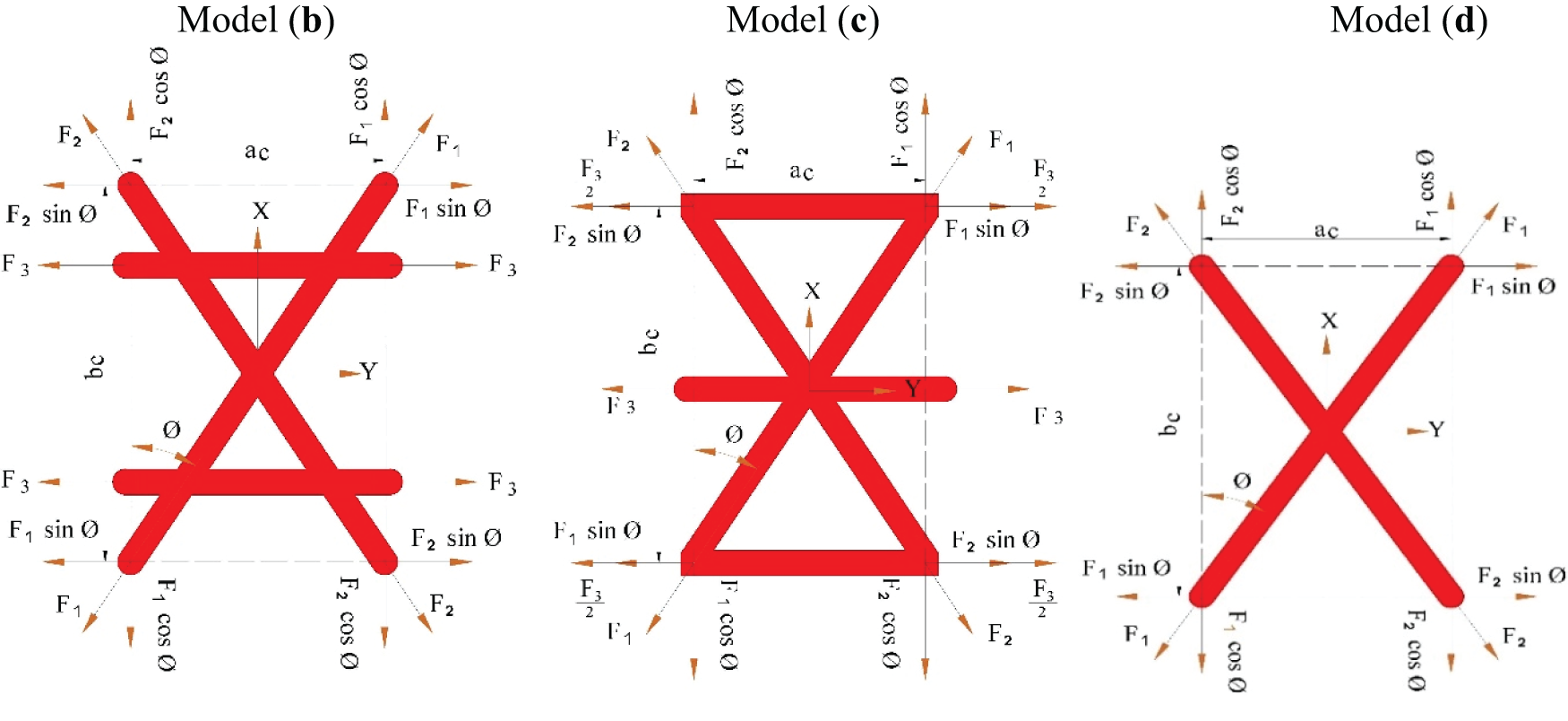
Figure A1: Forces diagram on a unit cell for models (b), (c), (d)
Fig. A2 shows the diagram of moments in unit cell for models (b), (c), (d) as follows:
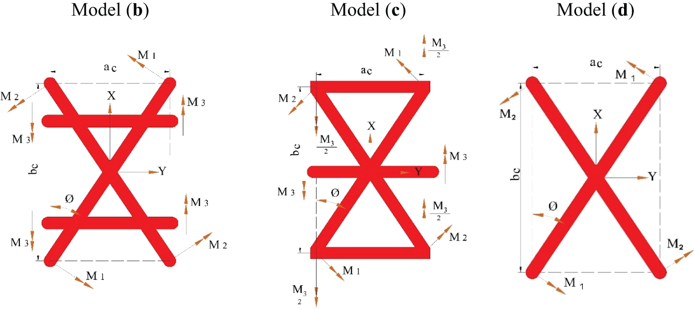
Figure A2: Moments diagram on a unit cell for models (b), (c), (d)
Stiffness matrices for cases of model (b) and model (c) are shown as follows:
Also, the stiffness matrix for model (d) is shown as follows:
The core
also, the core
After solving Eq. (24) using the Galerkin method, the parametric form of Eq. (27) is obtained. Then, by writing displacements U, V,
Formulas of area, the cross-sectional area of ribs, models (d), (c), and (b), respectively, are shown below:
Cite This Article
 Copyright © 2025 The Author(s). Published by Tech Science Press.
This work is licensed under a Creative Commons Attribution 4.0 International License , which permits unrestricted use, distribution, and reproduction in any medium, provided the original work is properly cited.


 Submit a Paper
 Propose a Special lssue
 View Full Text
 Download PDF
 Downloads
 Citation Tools