 Open Access
ARTICLE
A Decentralized and TCAM-Aware Failure Recovery Model in Software Defined Data Center Networks
Department of Computer System and Technology, University of Malaya, Kuala Lumpur, 50603, Malaysia
* Corresponding Author: Siti Hafizah AB Hamid. Email:
Computers, Materials & Continua 2025, 82(1), 1087-1107. https://doi.org/10.32604/cmc.2024.058953
Received 25 September 2024; Accepted 21 November 2024; Issue published 03 January 2025
Abstract
Link failure is a critical issue in large networks and must be effectively addressed. In software-defined networks (SDN), link failure recovery schemes can be categorized into proactive and reactive approaches. Reactive schemes have longer recovery times while proactive schemes provide faster recovery but overwhelm the memory of switches by flow entries. As SDN adoption grows, ensuring efficient recovery from link failures in the data plane becomes crucial. In particular, data center networks (DCNs) demand rapid recovery times and efficient resource utilization to meet carrier-grade requirements. This paper proposes an efficient Decentralized Failure Recovery (DFR) model for SDNs, meeting recovery time requirements and optimizing switch memory resource consumption. The DFR model enables switches to autonomously reroute traffic upon link failures without involving the controller, achieving fast recovery times while minimizing memory usage. DFR employs the Fast Failover Group in the OpenFlow standard for local recovery without requiring controller communication and utilizes the k-shortest path algorithm to proactively install backup paths, allowing immediate local recovery without controller intervention and enhancing overall network stability and scalability. DFR employs flow entry aggregation techniques to reduce switch memory usage. Instead of matching flow entries to the destination host’s MAC address, DFR matches packets to the destination switch’s MAC address. This reduces the switches’ Ternary Content-Addressable Memory (TCAM) consumption. Additionally, DFR modifies Address Resolution Protocol (ARP) replies to provide source hosts with the destination switch’s MAC address, facilitating flow entry aggregation without affecting normal network operations. The performance of DFR is evaluated through the network emulator Mininet 2.3.1 and Ryu 3.1 as SDN controller. For different number of active flows, number of hosts per edge switch, and different network sizes, the proposed model outperformed various failure recovery models: restoration-based, protection by flow entries, protection by group entries and protection by Vlan-tagging model in terms of recovery time, switch memory consumption and controller overhead which represented the number of flow entry updates to recover from the failure. Experimental results demonstrate that DFR achieves recovery times under 20 milliseconds, satisfying carrier-grade requirements for rapid failure recovery. Additionally, DFR reduces switch memory usage by up to 95% compared to traditional protection methods and minimizes controller load by eliminating the need for controller intervention during failure recovery. The results underscore the efficiency and scalability of the DFR model, making it a practical solution for enhancing network resilience in SDN environments.Keywords
Despite the promise of enhanced management and service availability offered by Software Defined Networking (SDN) [1], a range of new challenges are introduced. One of the key challenges that SDN must address is ensuring efficient recovery from link failures in the data plane [2]. Network failures significantly impact network performance and make services unavailable. A network is supposed to return to service after a failure in a matter of a few tens of milliseconds to meet the requirements of a carrier grade network (i.e., a recovery time of under 50 ms) [3]. Existing Data Center Networks (DCNs) provide a variety of critical and real-time services on a large scale [4]. Also, transport networks highly demand to reduce the latency for voice and video conversations because voice echo occurs at a delay of 50 ms to avoid the inconvenience that these echoes cause during conversations [5]. A study conducted on Google’s data centers and a set of wide area networks found that 80% of network component failures persisted for 10 to 100 min, leading to substantial packet loss [6]. Business sectors expect to lose more than $107,000 per h due to data center down-time cost, and IT outages result in the revenue loss of about $26.5 billion per year [7].
Recent advancements have extended SDN’s applicability to various domains, such as satellite networks [8] and vehicular networks [9], which bring unique demands for failure recovery. In satellite networks, SDN enables dynamic resource management and improved network efficiency [8]. In vehicular networks, intelligent SDN approaches offer enhanced flexibility and adaptability to changing network conditions [9]. These developments highlight the versatility of SDN but also underscore the importance of robust failure recovery mechanisms across different network types.
To address link failures, SDN-based link failure recovery mechanisms generally fall into two main categories: restoration and protection. In restoration, the controller plays an active role in the recovery process, whereas in protection, the data plane is capable of recovering from a failure independently, without the controller’s intervention [10–12]. During restoration, the controller reactively addresses the link failure by calculating a new backup path and updating the necessary flow entries in the affected switches after receiving a failure notification from the data plane elements. The communication between the impacted switches and the controller, combined with the process of calculating a new route and reconfiguring the data plane, adds extra load on the controller and introduces delays in failure recovery. Consequently, the recovery time is significantly impacted by the scale of the network, often failing to meet DCNs and Carrier-Grade Networks (CGNs) requirements for recovery time, which should be under 50 ms. However, in protection method, the flow entries of the backup paths are proactively installed at the data plane [13–15]. Thus, the protection approach does not depend on the number of the disrupted flows and does not include the controller in the recovery process. This enables protection method to meet the recovery time requirement of the carrier-grade networks. But the protection approach consumes much larger size of the switches’ Ternary Content-Addressable Memory (TCAM) compared to the restoration approach. The majority of commercial OpenFlow switches, according to [16,17], have an on-chip TCAM with a size of between 750 and 2000 OpenFlow rules. But according to recent studies, modern data centers can have up to 10,000 network flows per second for each server rack [18].
The prevailing models for link failure recovery often struggle with one or both of these issues: extended failure recovery times and considerable memory consumption in switches. Restoration-based recovery efficiently utilizes switch memory but suffers from higher recovery times due to controller dependency, which becomes significant in large-scale networks. Protection-based recovery meets recovery time requirements but at the cost of excessive TCAM consumption due to the proactive installation of backup paths. Additionally, with the expansion of SDN into new domains like satellite and vehicular networks, the need for efficient and scalable failure recovery mechanisms becomes even more critical [8,9]. Therefore, it is a critical requirement for a link failure recovery mechanism in SDN to achieve fast recovery times without imposing significant memory overhead on switches. This motivates our research to develop a solution that leverages the strengths of both restoration and protection methods while mitigating their drawbacks.
To address these challenges of recovery time and TCAM resource consumption in SDN-based networks, this paper proposes DFR (Decentralized Failure Recovery), a model that efficiently recovers from link failures without overloading the controller or consuming excessive switch memory. DFR leverages Fast-Failover groups in the OpenFlow standard and introduces an innovative approach to aggregate flow entries. The key contributions of this paper are highlighted as follows:
1. Proposed DFR Model: We introduce DFR, which autonomously reroutes affected flows without contacting the controller by proactively installing backup paths using the k-shortest path algorithm and Fast-Failover groups.
2. Innovative Flow Entry Aggregation: DFR reduces TCAM memory consumption by matching flow entries to the destination edge switch’s MAC address instead of the destination host’s MAC address, utilizing modified ARP replies to achieve this aggregation.
3. Comprehensive Evaluation: We evaluate DFR on Fat-tree topologies common in data centers, demonstrating that it reduces switch memory usage, meets carrier-grade network recovery time requirements (under 50 ms), and lessens controller processing overhead compared to existing models.
The rest of the paper is organized as follows. Section 2 reviews the related work of the link failure recovery. Section 3 presents the architecture of the DFR model and its modules. Section 4 presents the experimental setup, performance metrics and existing models. Section 5 introduces the results and discussion. Section 6 concludes this paper.
In the literature, many approaches have been proposed to optimize link failure recovery in Software-Defined Networks (SDN), each of them trying to enhance recovery speed, resource utilization, or reducing controller dependency. Table 1 presents a comprehensive comparison between the related works that proposed methods to address the link failure recovery challenges Reference [19] introduced a fast failover mechanism where the SDN controller proactively computes primary and backup paths. This proactive approach autonomously reroutes the disrupted flows that are traversing the failed link to backup paths upon a failure without communicating the controller. By utilizing asynchronous OpenFlow messages and packet buffering, the proposed approach considerably minimizes packet loss and reduces the recovery time, making it suitable for network environments that host critical and time-sensitive applications. However, this method consumes a significant amount of switch memory due to the proactive installation of backup paths, which can be problematic for switches with limited TCAM resources.
Reference [14] proposed a 1:1 path protection approach adopting the feature of Fast-Failover group tables introduced by OpenFlow standard. The evaluation conducted by this study show that the proposed approach minimizes the recovery time compared to restoration-based approaches and eliminating the overhead on the controller. However, these advantages introduce a considerable overhead to the switches’ memory in terms of memory size consumption because of proactively installing the backup paths at the switches.
In order to address the limitations of restoration approach, Reference [20] proposed two schemes: Controller Independent Path (CIP) and Controller Dependent Path (CDP). These protection-based approaches aim to reduce dependance on the controller during failures, decrease the number of flow entries to protect the working paths, and achieve faster recovery times. The results show that the proposed scheme considerably reduces the size of switch memory consumed for link protection in wide area networks (WANs). But they ignored the possibility that edge switches might operate with different VLANs and subnets, which could restrict the applicability of proposed schemes to simple network environments.
In the context of data centers, Reference [21] developed the Group Table Routing (GTR) approach, a hybrid method that efficiently handles link failures by grouping disrupted flows into a big flow and minimizing flow entry updates. Their approach reduces the size of switch memory required for protection and decreases recovery time. However, it introduces a significant processing overhead on the controller’s CPU and requires frequent installation, deletion, or modification of flow entries, which may impact the overall network performance.
Both References [16] and [22] focused on the efficient utilization of TCAM resources through hybrid approaches of restoration and protection. Reference [16] proposed a method aimed at optimizing TCAM usage, but it requires substantial processing at the controller, potentially leading to performance bottlenecks. Similarly, Zhu et al. emphasized TCAM efficiency but also faced challenges with high controller processing demands and the potential for inaccurate link classification, which could affect the reliability of the recovery process. These approaches may not scale well in large networks due to increased controller workload and possible inaccuracies in failure handling.
Reference [23] adopted the protection approach as failure recovery approach and leveraging the end-to-end ping method as a link failure detection method. It consumes a large amount of switch memory and experiences higher detection times due to the inherent latency of end-to-end ping operations. This approach may not be suitable for time-sensitive or large networks where fast recovery and minimal memory usage are priorities.
Lastly, Reference [13] introduced a protection strategy that enhances TCAM utilization and reduces recovery time through VLAN-based recovery. While the results show improvement in recovery times, the study requires a thorough evaluation of flow entry reduction instead of the used small experimental scale. Also, further experiments are required to evaluate its scalability and effectiveness in larger or more complex network setups.
In summary, while the proposed approaches address some of the key issues into link failure recovery in SDN, they introduce common issues:
• High TCAM Consumption: Many protection-based methods, such as those in [14] and [19], consume significant switch memory due to the proactive installation of backup paths.
• Limited Applicability: Approaches like [20] may not handle complex network environments with different VLANs and subnets, limiting their practicality.
• Controller Overhead: Hybrid methods from [21,16], and [22] often incur extra costs due to increased controller processing overhead, potentially leading to performance bottlenecks in large-scale networks.
• Detection Delays: Detection-based strategies, such as [23], face longer detection and recovery times due to reliance on latency-prone methods like end-to-end ping.
• Scalability Issues: Some studies, like [13], have not been thoroughly evaluated for scalability, raising concerns about their effectiveness in larger or more complex networks.
These technical gaps highlight the need for a link failure recovery mechanism that can:
• Achieve fast recovery times without imposing significant memory overhead on switches.
• Minimize controller processing demands to avoid performance bottlenecks.
• Be applicable in complex network environments with varying VLANs and subnets.
• Scale effectively in large and dynamic network topologies.
All of these unresolved issues, reinforce the necessity to propose new approach that combines the strengths of both protection and restoration approaches while mitigating their drawbacks. By innovatively aggregating flow entries and efficiently utilizing Fast-Failover mechanisms, the proposed approach DFR addresses the identified technical gaps, providing a scalable, memory-efficient, and rapid recovery solution for link failures in SDN.
This section presents a detailed description of the proposed model named Decentralized Failure Recovery (DFR) model. The proposed model abandons the centralized management approach in SDN and adopts a distributed management over the switches. In DFR, the link failure recovery logic is moved from the controller to forwarding devices at the data plane in order to locally reroute the traffic without the need for communicating the controller.
The architecture of the DFR model encompasses four key modules: Path Calculator, Destination Switch-based Aggregator, Fast-failover Groups Installer, and Address Resolution Protocol (ARP) Replier, as depicted in Fig. 1.
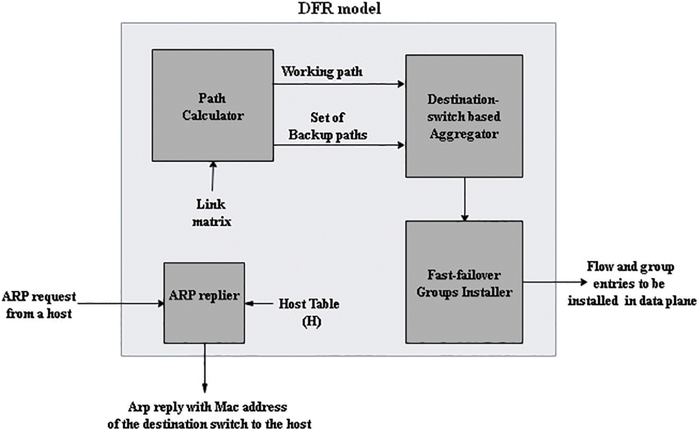
Figure 1: The architecture of DFR model
DFR adopts the per-link detection and per-link protection approach. In this approach, each link alongside the working path will be protected by a backup path to the neighbor switch. This module is responsible for calculating the working path between each two edge switches and a set of backup paths to protect each link along the working path.
Algorithm 1 depicts the pseudo-code of path calculator module at the controller. Path calculation module processes each packet entering the network G, extracting the source and destination IP addresses. It then calculates the working path (Wp) using the shortest path algorithm. For every link (si, sj) in the working path, the algorithm computes the link Protection Path (PP (si, sj)) by finding the shortest path between si and sj. These protection paths are appended to a list (PPWp), ensuring the network is protected against potential failures by providing alternative routes for traffic flow. Fig. 2 illustrates the flowchart of Algorithm 1.

Figure 2: The aggregated flow entry and the FF group

The algorithm’s complexity is determined by the number of unique flows and the network’s size. Since paths are calculated only once per flow—identified by unique source and destination addresses—it computes the working path using a shortest path algorithm with a time complexity of (O(|E| + |V| log |V|)), where (E) is the number of edges and (V) is the number of vertices. Protection paths for each link in the working path are then calculated through additional shortest path computations between adjacent nodes. Therefore, the overall complexity is (O(F times (|E| + |V| * log |V|))), where (F) is the number of unique flows.
3.2 Destination Switch-Based Aggregator
Because of that the TCAM in commodity switches is relatively small and can hold only a little number of flow rules, DFR exploits the aggregation of flow entries based on the MAC address of the destination switch, Fig. 2 presents the structure of the aggregated flow entry and the FF group. Destination switch is defined in this paper as the switch that the destination host is connected to. After the working and backup paths are calculated, this module will interpret these paths into a set of flow entries. The main idea of this module is to install a single aggregated flow entry that matches all of the flows that destined to the hosts that connected to the same switch, instead of installing a flow entry for each host in the network.
In this way, we can aggregate the group of flow entries that are required to forward the traffic that is destined to the group of hosts that are located on the same edge switch, to only one flow entry for this edge switch. Thus, the number of flow entries when applying destination switch-based aggregation will be:
where
3.3 Fast-Failover (FF) Groups Installer
This module is responsible for installing the aggregated flow entries, that are obtained by the destination switch-based aggregator module, into the flow tables of the switches in the data plane. The flow entry will only be matched to the destination switch MAC address field of the incoming packets with the action to forward the matching packets to a fast failover group. The fast failover group consists of two buckets: the first will forward the packets through the working path while the second bucket forwards the packets to the backup path. If the monitored port in the first bucket is down, the incoming matching flows to the flow entry will pass to bucket 2 which in turn will forward these flows through the backup path.

Algorithm 2 presents the pseudo-code of flow installer module at the controller. It takes the working path (Wp) and the list of protection paths (PPWp) as inputs. It iterates through each switch (si) in the working path. If the current switch is the last one in the main path, a simple flow entry is installed to this switch to forward the traffic to the destination host. Otherwise, a Fast-Failover (FF) group table is installed as illustrated in Fig. 2. The algorithm then iterates through each protection path (PP) in the list of protection paths (PPWp). For every link in the protection path, a simple flow entry is installed. Fig. 3 depicts the flowchart of Algorithm 2.
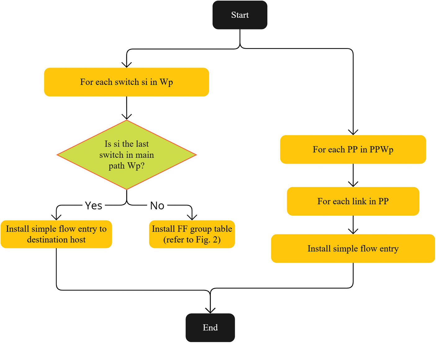
Figure 3: The flowchart of Algorithm 2
The complexity of Algorithm 2 is influenced by the number of unique flows and the lengths of their working and protection paths. Since paths are calculated only once per flow, the algorithm installs flow entries or group tables for each switch along the working path, which takes time proportional to the path length. It also processes each protection path in the list (PPWp), installing flow entries for every link in these paths. Thus, the overall time complexity is (O(F times (Lw + sum Lp))), where (F) is the number of unique flows, (Lw) is the length of the working path, and (sum Lp) represents the total lengths of all protection paths. The complexity scales with the number of flows and the combined lengths of their associated paths.
In traditional TCP/IP networks, inter-host communication necessitates the source host knowing the destination host’s MAC address to construct the packet header. In SDN networks, an ARP request from the source host is forwarded to the controller, which responds with an ARP reply containing the destination host’s MAC address. While the destination host’s MAC address is essential for communication in conventional networks, it is not a requirement for SDN-based networks to work properly, where packet matching to flow entries primarily depends on the destination IP address or any matching field [24,25].
DFR model takes advantage of this aspect, allowing the ARP replier module to send an ARP reply with the destination switch’s MAC address rather than the destination host’s MAC address. When an ARP request reaches the ingress edge switch, it forwards the request to the controller’s ARP replier module in DFR, which then consults the host table to find the MAC address of the destination switch that the destination host is connected to. The host table stores the mappings between host IP addresses, MAC addresses, VLAN IDs, switch IDs, and port numbers.
Algorithm 3 presents the pseudo-code of the ARP replier with inputs of the network G, which consists of a set of switches (V) and a set of links (E), as well as a host table (H). When an ARP request enters the network, it is forwarded to the ARP Proxy at the controller. The proxy then searches for the destination host’s IP address in the host table (H), and retrieves the MAC address of the destination switch to which the host is connected. The ARP proxy then constructs an ARP reply containing the destination switch’s MAC address and forwards it to the source host. This process enables the destination switch-based aggregator module to aggregate all flows destined for hosts on the same switch into a single large flow, as described in Algorithm 3 and in Fig. 4.
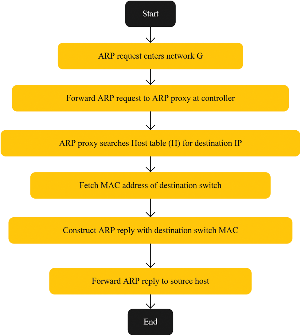
Figure 4: The flowchart of Algorithm 3

Regarding the parameters in the algorithms: 1, 2 and 3, we focus on three main parameters: the number of backup paths (k), aggregation level, and protection approach. We set (k = 1) by default, calculating one backup path per link. This choice aligns with our DFR approach, which aims to protect the network from failures rather than facilitate load balancing. Since most studies in the literature use only main and backup paths, setting (k = 1) provides effective protection without unnecessary complexity or resource consumption. For aggregation, we use the destination switch’s MAC address to be TCAM-aware and minimize the number of flow entries. While higher aggregation levels (like per VLAN) might reduce flow entries further, they may lack the necessary granularity for precise failure recovery. On the other hand, lower aggregation levels (per host) increase TCAM usage. Aggregating at the destination switch level strikes an optimal balance between granularity and resource utilization. Regarding the protection approach, we employ per-link protection, which ensures rapid recovery and robustness against failures by providing backup paths for each link, effectively safeguarding the network as intended.
In this section, we conduct a comprehensive evaluation of the proposed DFR model. The objective is to thoroughly assess the effectiveness of the DFR approach by comparing it against existing link failure recovery methods. This evaluation employs consistent experimental setups and testbeds to ensure the accuracy and reliability of our results. Key performance metrics: recovery time, the number of installed flow entries and the number of flow updates due to failure are utilized to demonstrate the efficiency and performance of the DFR model.
The Fat-Tree topology was chosen as the network topology for evaluation, a widely adopted configuration in data center networks, due to its relevance and extensive usage in real-world scenarios [26]. The experiments were conducted on a virtual machine hosted within a virtualized data center environment. The virtual machine was equipped with 8 CPU cores and 64 GB of RAM, running the Ubuntu 20.05.5 operating system. The network simulations were carried out using Mininet 2.3.1, Ryu 3.1, and OpenFlow 1.5. Mininet facilitated the creation of an emulated network environment, enabling us to connect the emulated network to the Ryu controller, which hosted the link failure recovery applications.
Simulating realistic network traffic is crucial for accurately evaluating link failure recovery methods. The Distributed Internet Traffic Generator (D-ITG) tool was utilized to create realistic traffic patterns by sending multiple flows between different hosts with specific flow parameters [27]. In our simulations, we used a packet size of 1024 bytes, with packets sent at a constant inter-arrival time at fixed and regular intervals, achieving a packet rate of 1000 packets per second. These parameters allowed us to simulate various network conditions and evaluate the recovery methods under diverse scenarios. Additionally, TShark [28], a network protocol analyzer, was employed to capture and analyze the packet flows. TShark provided detailed packet-level data, enabling us to accurately measure the recovery times of each recovery method. Table 2 presents the tools used in the experiments.

To objectively compare the DFR method with other recovery methods, evaluation involved several key performance metrics that were used in many studies [13,23,29]. These metrics provide a comprehensive evaluation of the efficiency and performance of each recovery method. The performance metrics considered in this evaluation include:
1) Recovery Time: The duration required to restore all flows affected by a failure. This metric is crucial for assessing the speed and efficiency of each recovery method. The recovery time is calculated using captures from TShark. By capturing traffic on the interfaces at the edges of the failed link, we can determine the failure recovery time. This is done by subtracting the timestamp of the last packet received before the failure from the timestamp of the first packet received on the second switch of the failed link after the failure for each affected flow. The recovery time is defined as the maximum value of all the individual failure recovery times for the affected flows.
2) Number of Flow Entries: This metric quantifies the number of flow and group entries. It represents the TCAM (Ternary Content-Addressable Memory) overhead in network switches.
3) Number of Flow Updates: This metric represents the number of flow entry modifications that is sent by the controller to the switches to recover from a failure. It provides insights into the overhead placed on the network controller during the recovery process. The number of flow updates was measured experimentally by counting the number of OpenFlow modification messages sent by the controller in response to the failure recovery. Table 3 presents the performance metrics considered for evaluation.

To verify the performance of proposed DFR, we compare it with the following four models:
1. Restoration [30]: It calculates backup paths upon the link failure using k-shortest path algorithm for each flow and installs flow entries at the switches alongside the calculated path.
2. Protection by flow entries [19]: It calculates backup paths using k-shortest path algorithm for each flow and installs flow entries with lower priority at the switches alongside the backup path proactively.
3. Protection by Group Entries [23]: It calculates backup paths using k-shortest path algorithm for each flow and installs proactively Fast-Failover group entries at the switches alongside the calculated path. Upon failure, the switch autonomously redirects the affected flows to the backup path.
4. Protection by Vlan-tagging [13]: It calculates backup paths using k-shortest path algorithm for each flow and installs proactively Fast-Failover group entries at the switches alongside the calculated path. For flow entries aggregation, it assigns a new VLAN ID to the packet’s VLAN field and installs flow entries at each switch in the protection path that match this VLAN ID to group all flows with this VLAN ID.
The Emulation process for each experiment involved the following steps:
1. Network Initialization:
• Set up the Fat-Tree topology in Mininet with the specified configuration.
• Start the Ryu controller and establish connections with all switches.
2. Controller Configuration:
• Deploy the DFR application or the respective recovery method’s application on the controller.
• Configure the controller to calculate paths and install flow entries according to the method being tested.
3. Flow Installation:
• For protection methods, flow entries and Fast-Failover groups were proactively installed before traffic generation.
• For the restoration method, flow entries were installed reactively upon flow initiation and modified upon failure detection.
4. Traffic Generation:
• Use D-ITG to generate traffic between randomly selected pairs of hosts, following the specified flow parameters.
• Ensure that traffic flows traverse the links intended to be failed during the experiment.
5. Failure Introduction:
• Introduce link failures at predetermined times using Mininet’s API disabling specific switch ports at predetermined times.
• Failures were introduced after the network had reached a steady state with ongoing traffic flows.
• Record the exact time of failure for accurate recovery time measurement.
6. Data Collection:
• Capture network traffic using TShark on relevant interfaces to measure recovery times.
• Monitor OpenFlow messages at the controller to count flow updates.
• Query switch flow tables to determine the number of flow entries installed.
7. Result Recording:
• Document the performance metrics for each method under the same network and traffic conditions.
• Repeat experiments ten times for each configuration to ensure statistical significance.
In this section, we investigate the correlation between network configurations and the performance of DFR and other recovery models. Our goal is to examine how factors such as the number of hosts per edge switch, active flows, and network size influence the efficiency of restoration, protection by flow entries, protection by group methods, protection by Vlan-tagging and DFR in terms of recovery time and installed flow entries count.
5.1 Number of Hosts Per Edge Switch vs. Number of Flow Entries, Recovery Time
The objective of these experiments is to investigate the relationship between the number of hosts per edge switch and the number of flow entries installed at the data plane, as well as the recovery time of all affected flows by the failed link. The experiment was conducted for different configurations of the number of hosts per edge switch, and the results were averaged over 10 runs for each configuration to ensure accuracy and account for potential variability. We compare the performance of DFR with other recovery methods, highlighting the efficiency and performance of the DFR approach.
Based on Figs. 5 and 6, it is evident that the DFR model demonstrates superior performance compared to other link failure methods. When considering the number of installed flow entries, DFR consistently results in fewer entries across all scenarios with varying numbers of hosts (1, 2, 4, and 8). This indicates that DFR is more efficient in managing flow entries, which could lead to reduced resource utilization and improved scalability.
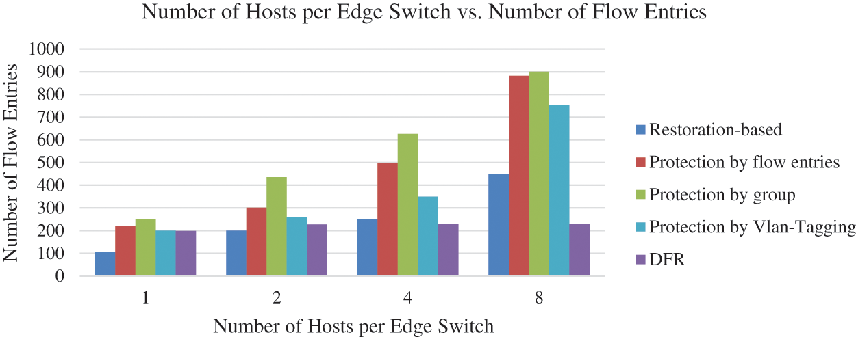
Figure 5: Number of hosts per edge switch vs. number of flow entries
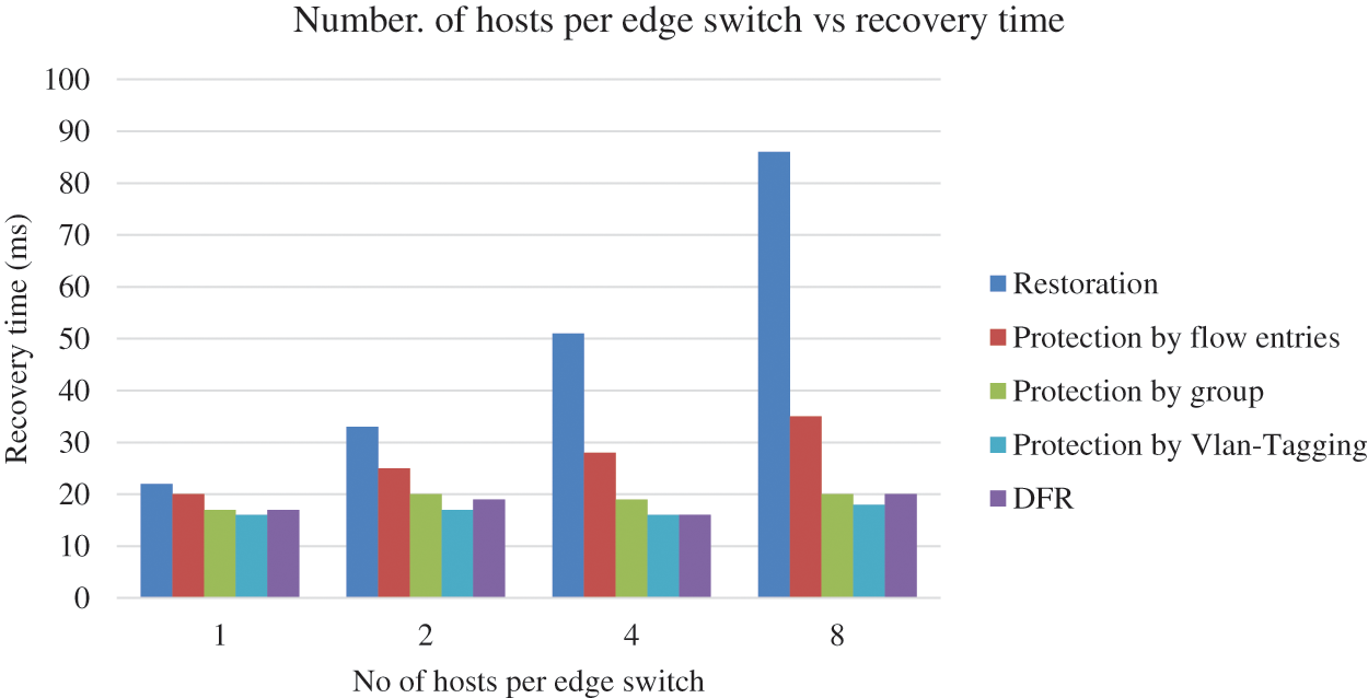
Figure 6: Number of hosts per edge switch vs. recovery time
Furthermore, the recovery time for DFR is also significantly lower compared to the restoration-based method and protection by flow entries method. In all scenarios, DFR shares almost the same recovery time as the protection by group method and protection by Vlan-Tagging, which ranges from 16 to 20 ms. In contrast, restoration-based recovery times range from 22 to 86 ms, and protection by flow entries recovery times range from 20 to 35 ms. This demonstrates that DFR is not only more efficient in terms of flow entry management but also provides faster recovery in the event of link failures.
5.2 The Relationship between the Number of Active Flows vs. the Number of Flow Entries, Recovery Time and the Number of Flow Updates
Understanding how the number of active flows affects recovery methods is essential for evaluating their scalability. This sub-section discusses the results of experiments examining the relationship between the number of active flows and the number of flow entries installed, along with recovery times. The comparison includes DFR and other methods.
The objective of these experiments is to investigate the relationship between the number of active flows running on the network and the number of flow entries installed at the data plane, as well as the recovery time of all affected flows by the failed link. The experiment was conducted for different configurations of the number of flows, and the results were averaged over 10 runs for each configuration to ensure accuracy and account for potential variability.
The graphs in Figs. 7 and 8, clearly demonstrate that DFR outperforms other link failure methods in both the number of installed flow entries and recovery time across different numbers of flows. When analyzing the number of installed flow entries, DFR consistently requires fewer entries than the restoration, protection by flow entries, protection by group and protection by Vlan-Tagging methods for all scenarios (12 to 60 flows). This indicates that DFR is more efficient in managing flow entries, leading to reduced resource consumption and improved scalability in the network.
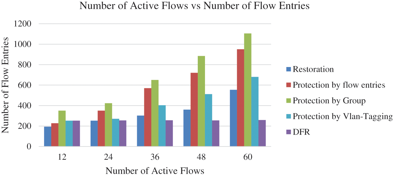
Figure 7: Number of active flows vs. number of flow entries
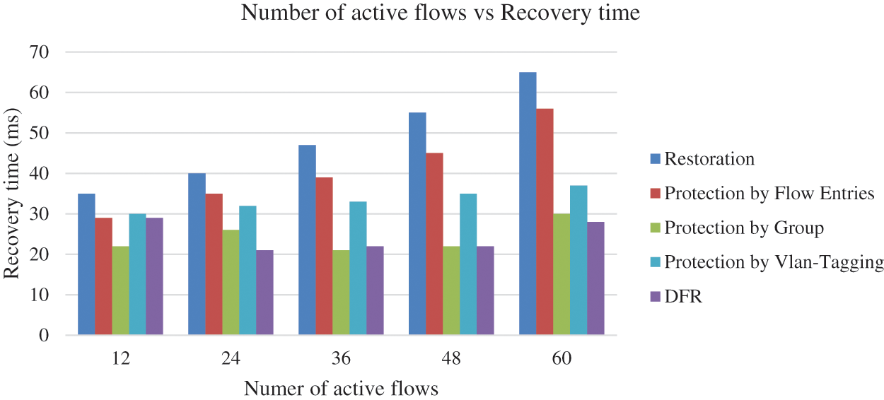
Figure 8: Number of active flows vs. recovery time
Furthermore, the recovery time for DFR is significantly lower compared to the other methods, including restoration, protection by flow entries. In all scenarios, DFR’s recovery times range from 21 to 29 ms, while the other methods exhibit higher recovery times. For instance, restoration-based recovery times range from 35 to 53.8 ms, protection by flow entries recovery times range from 49 to 69.1 ms, and protection by group recovery times range from 29 to 56 ms. This demonstrates that DFR not only provides better flow entry management but also ensures faster recovery in the event of link failures.
Fig. 9 illustrates the number of flow updates required to recover from a failure using various different methods across varying numbers of active flows in the network. As the number of active flows increases from 12 to 60, the number of flow updates needed for Restoration rises from 20 to 62. Similarly, Protection by Flow entries requires an increasing number of flow updates, starting at 15 for 12 flows and reaching 46 for 60 flows. Notably, the Protection by Group, Protection by Vlan-Tagging and DFR consistently require zero flow updates regardless of the number of active flows because the links are proactively protected. This indicates that while Restoration and Protection by Flow methods necessitate progressively more updates as the network activity increases, the Protection by Group, Protection by Vlan-Tagging and DFR method maintains its efficiency with no additional updates needed after a failure, which reduces the overload on the controller and the recovery time considerably.
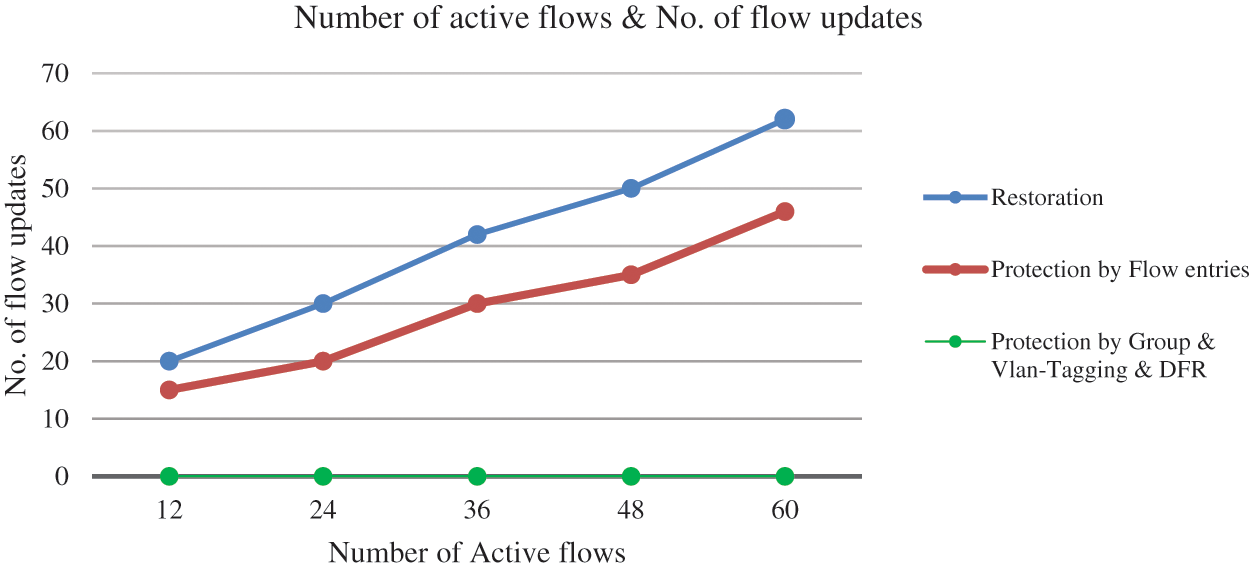
Figure 9: Number of active flows vs. number of flow updates
5.3 Network Size vs. Number of Flow Entries, Recovery Time and the Number of Flow Updates
Network size, defined by the number of pods and density, is a critical factor in the performance of recovery methods. This sub-section presents the results of experiments exploring the impact of network size on the number of flow entries and recovery times. We evaluate DFR’s performance relative to other methods, emphasizing its robustness and efficiency in larger network configurations.
The objective of these experiments is to investigate the relationship between network size (in terms of pods and density) and the number of flow entries installed at the data plane, as well as the recovery time of all affected flows by the failed link. Table 4 presents the Fattree topologies that are evaluated and the number of core switches, aggregation switches, edge switches and hosts for each topology. The experiment was conducted for different configurations of network size, and the results were averaged over 10 runs for each configuration to ensure accuracy and account for potential variability.

Figs. 10 and 11 demonstrate that DFR approach consistently outperforms other link failure methods in terms of both the number of installed flow entries and recovery times across various network configurations. In terms of installed flow entries, DFR exhibits superior efficiency across all network topologies. DFR requires fewer flow entries compared to restoration, protection by flow entries, protection by group and Protection by Vlan-Tagging methods leading to reduced resource consumption and improved network scalability.
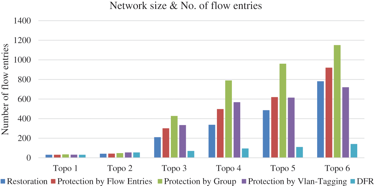
Figure 10: Network size vs. number of flow entries
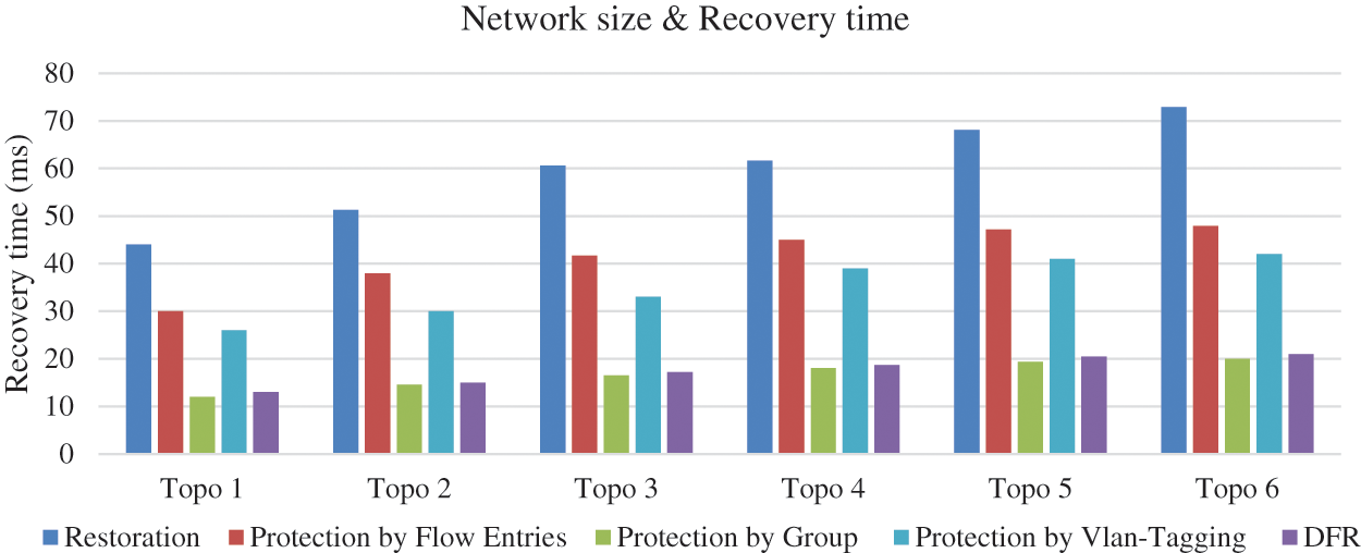
Figure 11: Network size vs. recovery time
Additionally, the recovery times for DFR are consistently lower than those of the restoration, protection by flow entries and Protection by Vlan-Tagging for all network configurations. While the recovery times for other methods increase as network size grows, DFR and Protection by group entries maintains relatively stable recovery times, ranging from 12 to 21 ms.
In conclusion, the proposed model (DFR) has proven to be an efficient and scalable model for managing link failures in software-defined DCNs, as demonstrated by the results. The DFR model’s efficiency stems from several key contributions:
1. Autonomous Traffic Rerouting: DFR introduces a decentralized approach that allows forwarding devices to autonomously reroute affected traffic upon link failures, eliminating the need for controller intervention and thereby reducing recovery delays.
2. Efficient Flow Entry Aggregation: We developed an innovative method to aggregate flow entries by matching packets to the destination switch’s MAC address rather than the destination host’s MAC address. This approach significantly reduces the number of flow entries required, addressing TCAM limitations in switches and improving resource efficiency.
3. Proactive Installation of Backup Paths: By proactively installing backup paths using the k-shortest path algorithm and employing Fast-Failover groups, DFR ensures immediate local recovery, meeting carrier-grade network requirements for minimal recovery times.
The DFR method also takes advantage of software-defined networking (SDN) features by leveraging the destination switch’s MAC address instead of the destination host’s MAC address. This modification further improves efficiency by enabling flow aggregation, thereby reducing the number of flow entries required. Our comprehensive evaluations demonstrate that the DFR model consistently outperforms other link failure recovery methods—including Restoration-based, Protection by Flow Entries, Protection by Group Entries, and Protection by VLAN-Tagging—across various scenarios and network configurations.
In summary, the Decentralized Failure Recovery (DFR) approach outperforms other link failure methods including: Restoration-based, Protection by flow entries, and Protection by group and Vlan-Tagging approaches by achieving less than 20 ms of recovery time in CGN networks for all the network and traffic load configurations. DFR achieves recovery times under 20 ms in all tested scenarios, meeting Carrier-Grade Network (CGN) requirements for recovery times under 50 ms. In respect to the number of flow entries which represents the TCAM size of switches, the evaluation proves that DFR is efficient and scalable and could be used for different network size and traffic load configurations. This substantial reduction contributes to improved resource efficiency, making DFR especially beneficial for large-scale networks with limited TCAM resources.
Future work should explore extending the proposed model’s capabilities to operate in various network topologies. Expanding the DFR model’s capabilities to operate effectively in other network topologies beyond Fat-Tree structures, such as Spine-Leaf and Mesh topologies, could further its applicability. Additionally, more comprehensive evaluations under diverse network conditions, including dynamic traffic patterns and different failure scenarios, will validate the model’s efficiency and scalability in real-world environments. Future enhancements will expand the applicability to various software-defined environments other Datacenters. These enhancements may also involve operating DFR across other environments beyond data centers, such as satellite networks and vehicular networks.
Acknowledgement: None.
Funding Statement: The authors received no specific funding for this study.
Author Contributions: Suheib Alhiyari contributed to the writing, design, implementation, and experimental result analysis of the proposed work. Siti Hafizah AB Hamid and Nur Nasuha Daud contributed to leading, reviewing, and removing grammatical problems. Each author participated sufficiently in the production to take public responsibility for the relevant percentage of the content. All authors reviewed the results and approved the final version of the manuscript.
Availability of Data and Materials: This article does not involve data availability, and this section is not applicable.
Ethics Approval: Not applicable.
Conflicts of Interest: The authors declare no conflicts of interest to report regarding the present study.
References
1. W. Rafique, L. Qi, I. Yaqoob, M. Imran, R. U. Rasool and W. Dou, “Complementing IoT services through software defined networking and edge computing: A comprehensive survey,” IEEE Commun. Surv. Tut., vol. 22, no. 3, pp. 1761–1804, 2020. doi: 10.1109/COMST.2020.2997475. [Google Scholar] [CrossRef]
2. T. Semong et al., “A review on software defined networking as a solution to link failures,” Sci. Afr., vol. 21, 2023, Art. no. e01865. doi: 10.1016/j.sciaf.2023.e01865. [Google Scholar] [CrossRef]
3. D. Turner, K. Levchenko, A. C. Snoeren, and S. Savage, “California fault lines: Understanding the causes and impact of network failures,” Comput. Commun. Rev., vol. 40, no. 4, pp. 315–326, 2010. doi: 10.1145/1851275.1851220. [Google Scholar] [CrossRef]
4. T. Zhang, Y. Lei, Q. Zhang, S. Zou, J. Huang and F. Li, “Fine-grained load balancing with traffic-aware rerouting in datacenter networks,” J. Cloud Comput., vol. 10, 2021, Art. no. 37. 2021. doi: 10.1186/s13677-021-00252-8. [Google Scholar] [CrossRef]
5. ITU-T, G.1010: End-User Multimedia QoS Categories. Geneva, Switzerland: ITU-T. 2001. [Google Scholar]
6. R. Govindan, I. Minei, M. Kallahalla, B. Koley, and A. Vahdat, “Evolve or die: High-availability design principles drawn from Google’s network infrastructure,” in SIGCOMM 2016-Proc. 2016 ACM Conf. Spec. Interes. Gr. Data Commun., 2016, pp. 58–72. doi: 10.1145/2934872.2934891. [Google Scholar] [CrossRef]
7. S. Sharma, D. Staessens, D. Colle, M. Pickavet, and P. Demeester, “In-band control, queuing, and failure recovery functionalities for openflow,” IEEE Netw., vol. 30, no. 1, pp. 106–112, 2016. doi: 10.1109/MNET.2016.7389839. [Google Scholar] [CrossRef]
8. W. Jiang, “Software defined satellite networks: A survey,” Digit. Commun. Netw., vol. 9, no. 6, pp. 1243–1264, Dec. 2023. doi: 10.1016/j.dcan.2023.01.016. [Google Scholar] [CrossRef]
9. B. Ravi et al., “Stochastic modeling for intelligent software-defined vehicular networks: A survey,” Computers, vol. 12, no. 8, 2023, Art. no. 162. doi: 10.3390/computers12080162. [Google Scholar] [CrossRef]
10. N. Khan, R. Bin Salleh, A. Koubaa, Z. Khan, M. K. Khan and I. Ali, “Data plane failure and its recovery techniques in SDN: A systematic literature review,” J. King Saud Univ.-Comput. Inf. Sci., vol. 35, no. 3, pp. 176–201, 2023. doi: 10.1016/j.jksuci.2023.02.001. [Google Scholar] [CrossRef]
11. S. Sharma, D. Staessens, D. Colle, M. Pickavet, and P. Demeester, “Enabling fast failure recovery in OpenFlow networks,” in 2011 8th Int. Workshop Design Reliable Commun. Netw. (DRCN), Krakow, Poland, 2011, pp. 164–171. [Google Scholar]
12. V. Muthumanikandan and C. Valliyammai, “Link failure recovery using shortest path fast rerouting technique in SDN,” Wirel. Pers. Commun., vol. 97, no. 2, pp. 2475–2495, 2017. doi: 10.1007/s11277-017-4618-0. [Google Scholar] [CrossRef]
13. H. Nurwarsito and G. Prasetyo, “Implementation failure recovery mechanism using VLAN ID in software defined networks,” Int. J. Adv. Comput. Sci. Appl., vol. 14, no. 1, pp. 709–714, 2023. doi: 10.14569/issn.2156-5570. [Google Scholar] [CrossRef]
14. S. Sharma, D. Staessens, D. Colle, M. Pickavet, and P. Demeester, “OpenFlow: Meeting carrier-grade recovery requirements,” Comput. Commun., vol. 36, no. 6, pp. 656–665, 2013. doi: 10.1016/j.comcom.2012.09.011. [Google Scholar] [CrossRef]
15. B. Raeisi and A. Giorgetti, “Software-based fast failure recovery in load balanced SDN-based datacenter networks,” in Proc. 6th Int. Conf. Inf. Commun. Manage. ICICM 2016, 2016, pp. 95–99. doi: 10.1109/INFOCOMAN.2016.7784222. [Google Scholar] [CrossRef]
16. B. Isyaku, K. B. A. Bakar, M. N. Yusuf, and M. S. M. Zahid, “Software defined networking failure recovery with flow table aware and flows classification,” in ISCAIE 2021-IEEE 11th Symp. Comput. Appl. Ind. Electron., 2021, pp. 337–342. doi: 10.1109/ISCAIE51753.2021.9431786. [Google Scholar] [CrossRef]
17. A. Vishnoi, R. Poddar, V. Mann, and S. Bhattacharya, “Effective switch memory management in OpenFlow networks,” in DEBS 2014-Proc. 8th ACM Int. Conf. Distrib. Event-Based Syst., 2014, pp. 177–188. doi: 10.1145/2611286.2611301. [Google Scholar] [CrossRef]
18. Z. Liu, M. Lian, J. Guo, and G. Wang, “An efficient flow detection and scheduling method in data center networks,” in ACM Int. Conf. Proc. Ser., 2021, Art. no. 89. doi: 10.1145/3448734. [Google Scholar] [CrossRef]
19. N. M. Sahri and K. Okamura, “Fast failover mechanism for software defined networking-openflow based,” in ACM Int. Conf. Proc. Ser., 2014, Art. no. 16. doi: 10.1145/2619287.2619303. [Google Scholar] [CrossRef]
20. P. Thorat, S. Jeon, and H. Choo, “Enhanced local detouring mechanisms for rapid and lightweight failure recovery in OpenFlow networks,” Comput. Commun., vol. 108, pp. 78–93, 2017. doi: 10.1016/j.comcom.2017.04.005. [Google Scholar] [CrossRef]
21. S. Petale and J. Thangaraj, “Link failure recovery mechanism in software defined networks,” IEEE J. Sel. Areas Commun., vol. 38, no. 7, pp. 1285–1292, Jul. 2020. doi: 10.1109/JSAC.2020.2986668. [Google Scholar] [CrossRef]
22. Z. Zhu, H. Yu, Q. Liu, D. Liu, and B. Mei, “FFRLI: Fast fault recovery scheme based on link importance for data plane in SDN,” Comput. Netw., vol. 237, 2023, Art. no. 110062. doi: 10.1016/j.comnet.2023.110062. [Google Scholar] [CrossRef]
23. S. S. Kumar, S. Sharathkumar, R. Scholar, and N. Sreenath, “A fast failover technique for link failures and proactive controller based fault recovery mechanism in software deened networks a fast failover technique for link failures and proactive controller based fault recovery mechanism in software defined network,” 2022. doi: 10.21203/rs.3.rs-1975833/v1. [Google Scholar] [CrossRef]
24. R. Di Lallo, G. Lospoto, M. Rimondini, and G. Di Battista, “How to handle ARP in a software-defined network,” in 2016 IEEE NetSoft Conf. Workshops (NetSoft), Seoul, Republic of Korea, 2016, pp. 63–67. doi: 10.1109/NETSOFT.2016.7502444. [Google Scholar] [CrossRef]
25. A. Banjar, P. Pupatwibul, and R. Braun, “Comparison of TCP/IP routing versus OpenFlow table and implementation of intelligent computational model to provide autonomous behavior,” in Computational Intelligence and Efficiency in Engineering Systems. Cham: Springer, 2015, vol. 595, pp. 121–142. doi: 10.1007/978-3-319-15720-7_9. [Google Scholar] [CrossRef]
26. D. Guo, “State-of-the-art DCN topologies,” in Data Center Networking. Singapore: Springer Nature Singapore, 2022, pp. 25–56. doi: 10.1007/978-981-16-9368-7_2. [Google Scholar] [CrossRef]
27. A. Botta, A. Dainotti, and A. Pescapé, “A tool for the generation of realistic network workload for emerging networking scenarios,” Comput. Netw., vol. 56, no. 15, pp. 3531–3547, 2012. doi: 10.1016/j.comnet.2012.02.019. [Google Scholar] [CrossRef]
28. The Wireshark Foundation. Wireshark (Version 4.0.8) [software]. Accessed: Jan. 1, 2024. Available: https://www.wireshark.org/ [Google Scholar]
29. P. Thorat, S. M. Raza, D. S. Kim, and H. Choo, “Rapid recovery from link failures in software-defined networks,” J. Commun. Netw., vol. 19, no. 6, pp. 648–665, 2017. doi: 10.1109/JCN.2017.000105. [Google Scholar] [CrossRef]
30. H. Amarasinghe, A. Jarray, and A. Karmouch, “Fault-tolerant IaaS management for networked cloud infrastructure with SDN,” in IEEE Int. Conf. Commun., Paris, France, 2017, pp. 1–7. doi: 10.1109/ICC.2017.7996342. [Google Scholar] [CrossRef]
Cite This Article
 Copyright © 2025 The Author(s). Published by Tech Science Press.
This work is licensed under a Creative Commons Attribution 4.0 International License , which permits unrestricted use, distribution, and reproduction in any medium, provided the original work is properly cited.


 Submit a Paper
 Propose a Special lssue
 View Full Text
 Download PDF
 Downloads
 Citation Tools