 Open Access
ARTICLE
A Lightweight UAV Visual Obstacle Avoidance Algorithm Based on Improved YOLOv8
1 College of Computer Science and Technology, Xinjiang University, Urumqi, 830046, China
2 Signal Detection and Processing Autonomous Region Key Laboratory, Xinjiang University, Urumqi, 830046, China
3 Xinjiang Uygur Autonomous Region Research Institute of Measurement and Testing, Urumqi, 830000, China
* Corresponding Author: Zhenhong Jia. Email:
Computers, Materials & Continua 2024, 81(2), 2607-2627. https://doi.org/10.32604/cmc.2024.056616
Received 26 July 2024; Accepted 25 September 2024; Issue published 18 November 2024
Abstract
The importance of unmanned aerial vehicle (UAV) obstacle avoidance algorithms lies in their ability to ensure flight safety and collision avoidance, thereby protecting people and property. We propose UAD-YOLOv8, a lightweight YOLOv8-based obstacle detection algorithm optimized for UAV obstacle avoidance. The algorithm enhances the detection capability for small and irregular obstacles by removing the P5 feature layer and introducing deformable convolution v2 (DCNv2) to optimize the cross stage partial bottleneck with 2 convolutions and fusion (C2f) module. Additionally, it reduces the model’s parameter count and computational load by constructing the unite ghost and depth-wise separable convolution (UGDConv) series of lightweight convolutions and a lightweight detection head. Based on this, we designed a visual obstacle avoidance algorithm that can improve the obstacle avoidance performance of UAVs in different environments. In particular, we propose an adaptive distance detection algorithm based on obstacle attributes to solve the ranging problem for multiple types and irregular obstacles to further enhance the UAV’s obstacle avoidance capability. To verify the effectiveness of the algorithm, the UAV obstacle detection (UAD) dataset was created. The experimental results show that UAD-YOLOv8 improves mAP50 by 3.4% and reduces GFLOPs by 34.5% compared to YOLOv8n while reducing the number of parameters by 77.4% and the model size by 73%. These improvements significantly enhance the UAV’s obstacle avoidance performance in complex environments, demonstrating its wide range of applications.Keywords
Obstacle avoidance algorithms can assist UAVs to navigate autonomously in complex environments and avoid collision and damage, which is particularly important in fields such as industrial inspection, agricultural monitoring and disaster assessment. UAV obstacle avoidance algorithms include vision-based and non-vision-based algorithms. Among them, vision-based obstacle avoidance algorithms have become the focus of research because they can obtain rich environmental information and are applicable to a variety of application scenarios. The common visual obstacle avoidance algorithms include Optical Flow-based obstacle avoidance [1], structured light [2] and deep learning-based obstacle avoidance algorithms. Deep learning-based visual obstacle avoidance algorithms have higher robustness in complex environments due to their powerful feature extraction and classification capabilities.
Monocular cameras are widely used due to their low cost, small size, light weight, and inclusion of rich RGB image information. For example, Capi et al. proposed an algorithm that trains collision data through a convolutional neural network and returns the probabilities of the corresponding control actions [3]. Dai et al. trained an unmanned and collision dataset with a convolutional neural network, outputting steering angles and collision probabilities, which were mapped to UAV yaw angles and linear velocities [4]. Akremi et al. realized UAV obstacle avoidance in indoor corridors by classifying UAV obstacle avoidance actions as left, right, and forward through deep learning [5]. Because end-to-end obstacle avoidance algorithms do not explicitly measure the distance to obstacles, they may result in the drone either getting too close to obstacles or prematurely executing flight maneuvers during the avoidance process. Additionally, shallow convolutional neural networks have limited adaptability in handling complex environments.
Monocular cameras can estimate the relative distance between a UAV and obstacles through depth estimation. Mancini et al. constructed a depth network that combines depth estimation and obstacle detection [6]. Zhang et al. estimated depth from RGB images via a convolutional neural network and passed it to an obstacle avoidance system [7]. Yang et al. proposed an online adaptive CNN to enhance the performance of monocular depth estimation and transformed the depth map into Ego Dynamic Space for obstacle avoidance planning [8]. While depth estimation aids in obstacle avoidance, monocular depth estimation is prone to high error, noise, and challenges in balancing real-time performance with accuracy. In contrast, RGB-D cameras provide direct depth information, enhancing the reliability of obstacle avoidance. Deep reinforcement learning (DRL) algorithms have been widely explored in the fields of self-directed UAV navigation and obstacle avoidance. Shen et al. utilized point clouds for outdoor obstacle detection, obstacle avoidance, and pathfinding [9]. Xue et al. used soft-actor-critic algorithm to train UAVs bypass obstacles within a continuous motion spatial [10]. Kalidas et al. investigated Deep Q-Networks and proximal policy optimization and soft-actor-critic, which are DRL algorithms for UAV obstacle avoidance using only image data [11]. In virtual environments, UAVs can navigate through simulations and interact with the environment repeatedly to continuously optimize their strategies in a trial-and-error manner. However, RGB-D cameras are expensive, and transferring deep reinforcement learning algorithms from simulation to real-world applications presents additional challenges.
Target detection algorithms are widely used on UAVs. Levkovits-Scherer et al. used MobileNet-SSD model to detect and avoid obstacles in outdoor environments without relying on GPS [12]. Lee et al. used Faster R-CNN for tree detection and avoidance with a set control strategy in order to make the UAV fly safely in the woods, using tree detection frame image height to represent their distance from the UAV and the image width between trees to find the widest obstacle-free zone [13]. YOLO series algorithm [14–18] can quickly obtain the most useful information from the rich RGB images, and are suitable for target detection in UAV viewpoints in terms of real-time and accuracy. Zhang proposed Drone-YOLO based on the YOLOv8 algorithm to solve the problem of the difficulty of detecting small targets in large scenes in UAVs [19]. Tahir et al. proposed PVswin-YOLOv8s based on YOLOv8s by combining Swin Transformer module with convolutional block attention module (CBAM) and Soft-NMS to solve the problem of difficult detection of small targets and occluded objects in UAV detection [20]. Fu et al. proposed DLSW-YOLOv8n algorithm combining deformable large kernel network, SPD-Conv, and Wise-IOU to improve the detection accuracy of UAV sea rescue missions [21]. Target detection algorithms often face a trade-off between speed and accuracy. The lightweight models of the YOLO family of algorithms strike a good balance between the two, providing relatively high accuracy and relatively good real-time performance. However, these lightweight models still face the challenges of large parameter counts and high computational effort.
To overcome the problems of large depth estimation error of monocular camera and high cost of RGB-D camera, we use binocular camera for detection and depth information acquisition. To address the problems of the YOLO algorithm’s large parameter count, large model, and poor detection of small targets and occlusions, we make several improvements to YOLOv8n. By removing the P5 feature layer, adding a layer of C2f module after the first standard convolution, performing layer-specific substitutions of the convolutions in the network by the constructed UGDConv series of convolutions, as well as replacing C2f with C2f-DCNv2 and using a lightweight detection head, we constructed a UAD-YOLOv8 that is both performant and lightweight. Based on the model, we designed an obstacle avoidance algorithm that can obtain the type and relative position of obstacles, within a set detection range, so that the UAV can detect and avoid obstacles and adapt to a variety of complex environments. The contributions of this thesis can be summarized as follows:
1) A lightweight UAD-YOLOv8 obstacle detection network with a very small number of model parameters and model size is proposed. It has no increase in computational effort with a significant reduction in the number of parameters, and the number of detection head parameters is extremely small.
2) UAD-YOLOv8 still achieves improved accuracy on a lightweight basis and is suitable for UAVs with limited computing resources.
3) The UAV visual obstacle avoidance algorithm was designed, and an adaptive distance detection algorithm based on obstacle attributes and a specific obstacle avoidance strategy generation method were proposed. The UAV common obstacle detection (UAD) dataset was produced.
The rest of the paper is organized as follows. Section 2 presents related work. Section 3 describes the lightweight UAD-YOLOv8 and visual obstacle avoidance algorithms as well as the adaptive distance detection algorithm based on obstacle attributes. Section 4 discusses the experimental dataset and experimental results. Finally, Section 5 gives conclusion and future work.
2.1 YOLO Algorithm for UAV Obstacle Avoidance
The YOLO family of algorithms significantly improves the safety of UAV navigation through the fast identification of obstacles. Zhang et al. combined YOLOv3 with the traditional method of speckle detection for UAV environment sensing [22]. She et al. used YOLOv3 to detect the area of obstacles and determine the obstacles through the principle of vision expansion [23]. Wang et al. combined the depth information obtained from an RGB-D depth camera with YOLOv3 to set up an obstacle avoidance strategy for UAV obstacle avoidance planning with respect to common obstacles in farmland [24]. Canh et al. used an RGB-D camera to recognize obstacles through YOLOv8 and clustered the point clouds corresponding to the obstacles and combined them with 2D metric maps to generate a probability map for obstacle avoidance path planning [25]. Liu et al. used YOLOv8 in the environment sensing module of UAV in order to solve the effect of the variability between obstacles on path planning. Based on the detection results, an environment-based adaptive optimal threat distance calculation module was established and applied to the improved path planning algorithm [26].
In order to improve the efficiency of UAV obstacle detection, existing target detection algorithms are difficult to balance between accuracy and lightweight. The lightweight improvement study for YOLOv8 shows that through reasonable module design and optimization, the YOLOv8 variant can achieve efficient detection while ensuring lightweight. For example, Ma et al. constructed a lightweight model by improving the Backbone part through the ShuffleNetv2 basic module, using the Ghost module instead of Conv, the C2f module in the Neck part replaced by C2f-Ghost, and adding the SE module into the network structure at the same time [27]. Du et al. added Partial Convolution (PConv) into the detection head part and used DCNv2 for C2f to achieve the purpose of recognizing irregular defects in Printed Circuit Boards [28]. Huangfu et al. constructed LW-YOLOv8 for detecting small targets in UAV aerial photography by introducing SE module and using GSConv convolution [29]. Yue et al. designed LHGNet backbone network based on depth-wise separable convolution with channel scrubbing module in order to increase the detection accuracy while lightweighting, and introduced LGS bottleneck and LGSCSP fusion module to construct the LE-YOLO [30].
In this paper, the proposed method differs from previous methods in the following ways:
1) Lightweight UAD-YOLOv8 for obstacle detection by deleting the P5 feature layer, the constructed UGDConv series of lightweight convolution only targeted replacement of the convolutional layers in the network, the network structure does not rely on the addition of the attention mechanism.
2) The UAV only needs to be equipped with a simple, low-cost binocular camera combined with a UAV visual obstacle avoidance algorithm based on the lightweight UAD-YOLOv8 for obstacle recognition and avoidance, without the need to generate any 3D maps.
3) The visual obstacle avoidance algorithm in this paper is not limited to obstacle detection, but can also avoid obstacles based on the depth value of the set center area. In view of the concavity and convexity of the obstacles and the possible outliers in the depth values, we filter and average the depth values corresponding to the center point of the obstacle and its surrounding points as the distance between the UAV and the obstacle.
Autonomous obstacle avoidance algorithms are particularly important when UAVs perform tasks such as autonomous inspections, where they often encounter unexpected or unintended obstacles. Target detection algorithms are well suited for detecting obstacles in flight, and fast and lightweight detection algorithms are of great interest. To meet these needs, we have improved the YOLOv8 algorithm and designed a UAV visual obstacle avoidance algorithm based on it.
YOLOv8n, the smallest version of the YOLOv8 series, has gained much attention for its excellent performance on mobile devices with limited computational resources. However, YOLOv8n still has a high number of parameters and a large model size. Additionally, like most existing detection algorithms, the YOLOv8 family is prone to miss small-target obstacles in UAV obstacle detection tasks and suffer from degraded detection accuracy in the face of dense obstacle occlusion. Therefore, we propose a lightweight target detection algorithm UAD-YOLOv8 based on YOLOv8n for UAV obstacle detection. As shown in Fig. 1, the proposed network is divided into three parts, backbone, neck module and detection head.
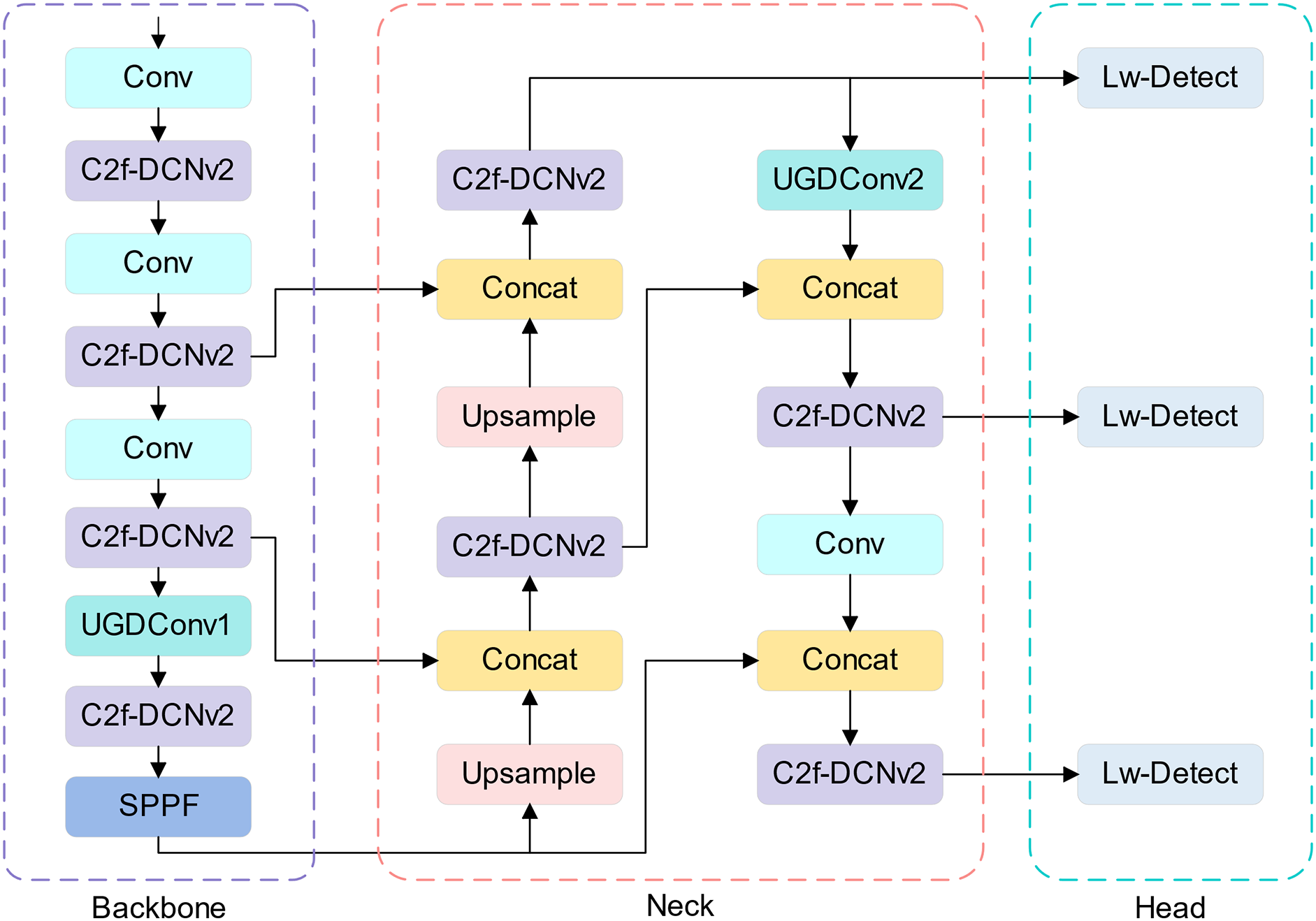
Figure 1: UAD-YOLOv8 network structure diagram
First, we delete the P5 feature layer in the original network structure, which is mainly considered that most of the images in the UAV view are small targets. To compensate for the effect of deleting the P5 feature layer, we add the C2f module after the first convolution. This adjustment enhances the feature extraction capability with little change in computation. There will be irregular features in obstacles, and the mutual occlusion of obstacles will lead to the incomplete shape and lead to the irregularity of perception. At the same time, due to the instability of the UAV in the air, this can lead to distortion in the detection image. Since standard convolution is weak to irregular features, we use DCNv2 [31] to replace the second standard convolutional layer in Bottleneck of C2f. The structure of C2f-DCNv2 is shown in Fig. 2. This improves the extraction ability of irregular features while enhancing the C2f module’s detection capability for small targets, which makes the feature fusion performance of the C2f module more powerful, thus helping the UAV to better perceive the surrounding environment. In addition, to achieve the ultimate lightweight of the model, we replace the original detection head with Lw-Detect and replace the standard convolution of specific layers in the network structure with UGDConv.

Figure 2: C2f-DCNv2 structure diagram
3.2 UGDConv Series of Lightweight Convolution and Lw-Detect Head
Ghost convolution [32] is widely used by everyone due to its great savings in the number of parameters and Floating Point Operations (FLOPs). Suppose, the input data is
Depth-wise separable convolution consists of depth-wise convolution and point-wise convolution, which is an efficient convolutional algorithm [33]. The parametric quantity of the depth-wise convolution can be denoted as
We combine the advantages of Ghost convolution and depth-wise separable convolution to build a highly efficient convolution module UGDConv1. In contrast to the operation of joining two parts in Ghost convolution, we directly connect the outputs of the two sub-parts in series to the depth-wise separable convolution part, which is optimized to form the convolution module UGDConv2. In UGDConv2, the second depth-wise separable convolution uses grouped convolution [34] due to the different number of input channels and output channels. The UGDConv series of lightweight convolution structures is shown in Fig. 3 below.
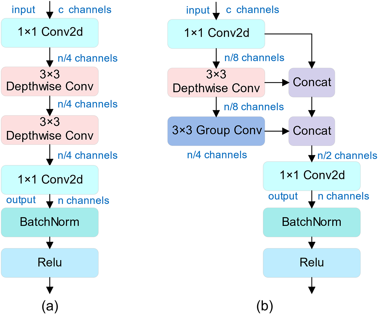
Figure 3: (a) UGDConv1 (b) UGDConv2
The parametric quantities and calculations (both ignored Batch Normalization and Relu) for UGDConv1 and UGDConv2 are shown in Eqs. (7)–(10).
We apply UGDConv1 to the last convolutional layer of the Backbone part of UAD-YOLOv8, which not only reduces the redundant feature maps in the feature extraction part but also maintains a high feature expressiveness. We also use the UGDConv2 module to replace the standard convolution in the 16th layer in the Neck, which further reduces the number of parameters. We use the UGDConv2 module for the detection head part by first deleting one of the two standard convolutions. Then, the remaining standard convolution is replaced by UGDConv2 to form a kind of lightweight detection head, Lw-Detect, which is structured as shown in Fig. 4 below.

Figure 4: Lw-Detect head structure
We set the ratio of the number of parameters in the normal convolution to the number of parameters in the UGDConv1, UGDConv2, Ghost convolution, and depth-wise separable convolution to
In our structure, at the 7th convolutional layer, when
3.3 Overview of UAV Obstacle Avoidance Algorithm
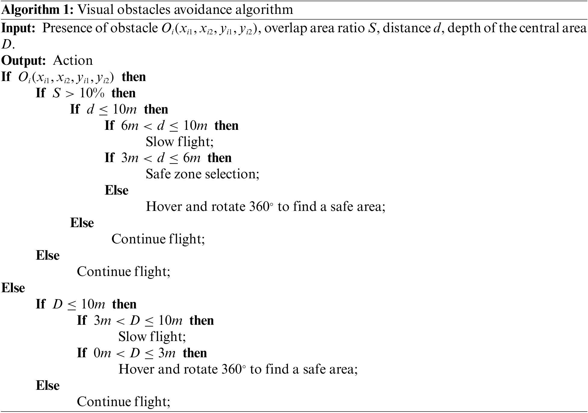
The overall framework of UAV obstacle avoidance is shown in Fig. 5. The UAV visual obstacle avoidance algorithm based on UAD-YOLOv8 is shown in Algorithm 1. Algorithm 1 flowchart is shown in Fig. 6. The UAD-YOLOv8 algorithm is used to detect common obstacles, obtain depth information by binocular camera, and then fusion the detection information and depth information. After the obstacle type and position information obtained by the UAD-YOLOv8 algorithm, the corresponding depth information is called up, and the distance between the UAV and the obstacle is obtained by our proposed adaptive distance detection algorithm, and the relative positional relationship between the obstacle and the UAV is further obtained, so as to perform obstacle avoidance.

Figure 5: Overall framework of UAV visual obstacle avoidance based on UAD-YOLOv8
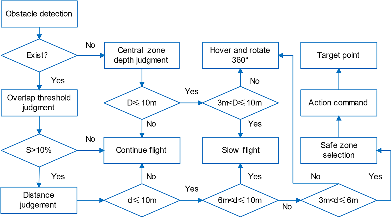
Figure 6: The flow chart of Algorithm 1
3.3.2 UAV Obstacle Distance Detection
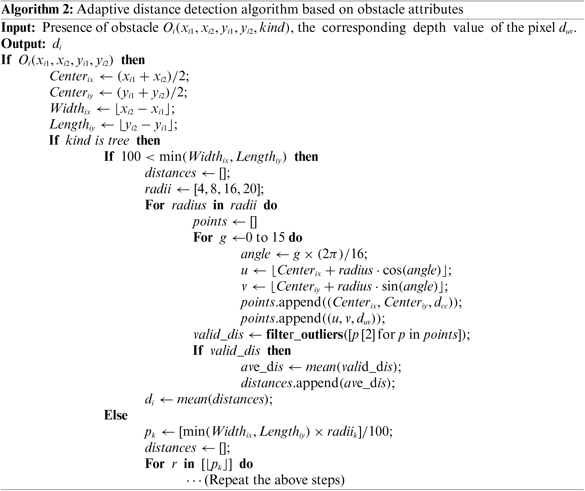
We use the Semi-Global Block Matching algorithm (SGBM) [35] with a binocular camera for UAV-to-obstacle distance detection. However, the SGBM algorithm may have too large or too small distance measurements in practical applications and is affected by lighting and camera jitter. To tackle these problems, we propose an adaptive distance detection algorithm based on obstacle attributes (see Algorithm 2). The algorithm takes the center point of the obstacle detection box as the center of the circle and selects a specific pixel circle radius based on the attributes of the obstacle. Subsequently, the radius of the circle is scaled based on the size of the detection box. After selecting the depth values corresponding to the pixel points on the circle and at the center of the circle, the algorithm performs outlier removal and averaging as shown in Algorithm 2. Fig. 7 shows the flowchart of Algorithm 2.

Figure 7: The flow chart of Algorithm 2
3.3.3 Selection of Safe Areas for Drones
After obstacle detection, it is also necessary to select the next safe region for the drone. We set a central region in the left camera field of view of the drone, which projects a region with a side length of 1 meter 3 meters in front of the drone to the center of the field of view and performs an expansion of the drone volume. The drone searches for the largest area free of obstacles and uses the center of this area as the next navigation point for the drone to return to the preset path. The UAV viewpoint diagram is shown in Fig. 8. The division of obstacle avoidance ranges for UAVs is shown in Fig. 9a.
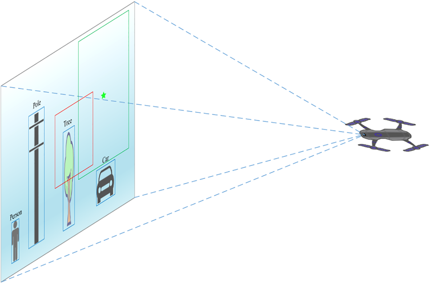
Figure 8: UAV viewpoint diagram. The red line area is the center area of the setup, the green line area is the safe flight area, the green pentagram indicates the safe flight center
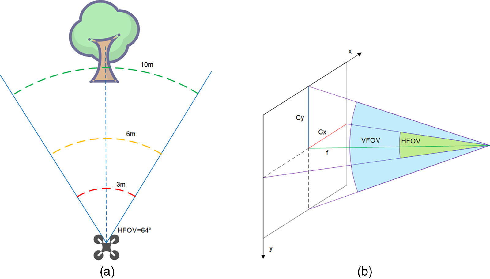
Figure 9: (a) Dividing the obstacle avoidance range for the UAV. We set 10 m as the safety threshold and divide 10 m into 3 parts, the first part is 10–6 m is the deceleration range, the second part is 6–3 m is the range to find the safe flight area, and the third part is 3–0 m is the danger range. (b) Horizontal field of view and vertical field of view of the camera
During UAV flight, special situations may be encountered, such as the viewpoint being completely occupied by a wall, which invalidates obstacle detection. When no obstacle is detected in the UAV viewpoint, we determine the depth value
3.3.4 UAV Obstacle Avoidance Action Command
Based on the difference between the pixel value of the center point of the largest area without obstacles and the center point of the imaging, and the horizontal field of view (HFOV), the value of the change in yaw angle is obtained in the next step, and the field of view is shown in Fig. 9b. The UAV field of view is shown in Eqs. (11) and (12).
The
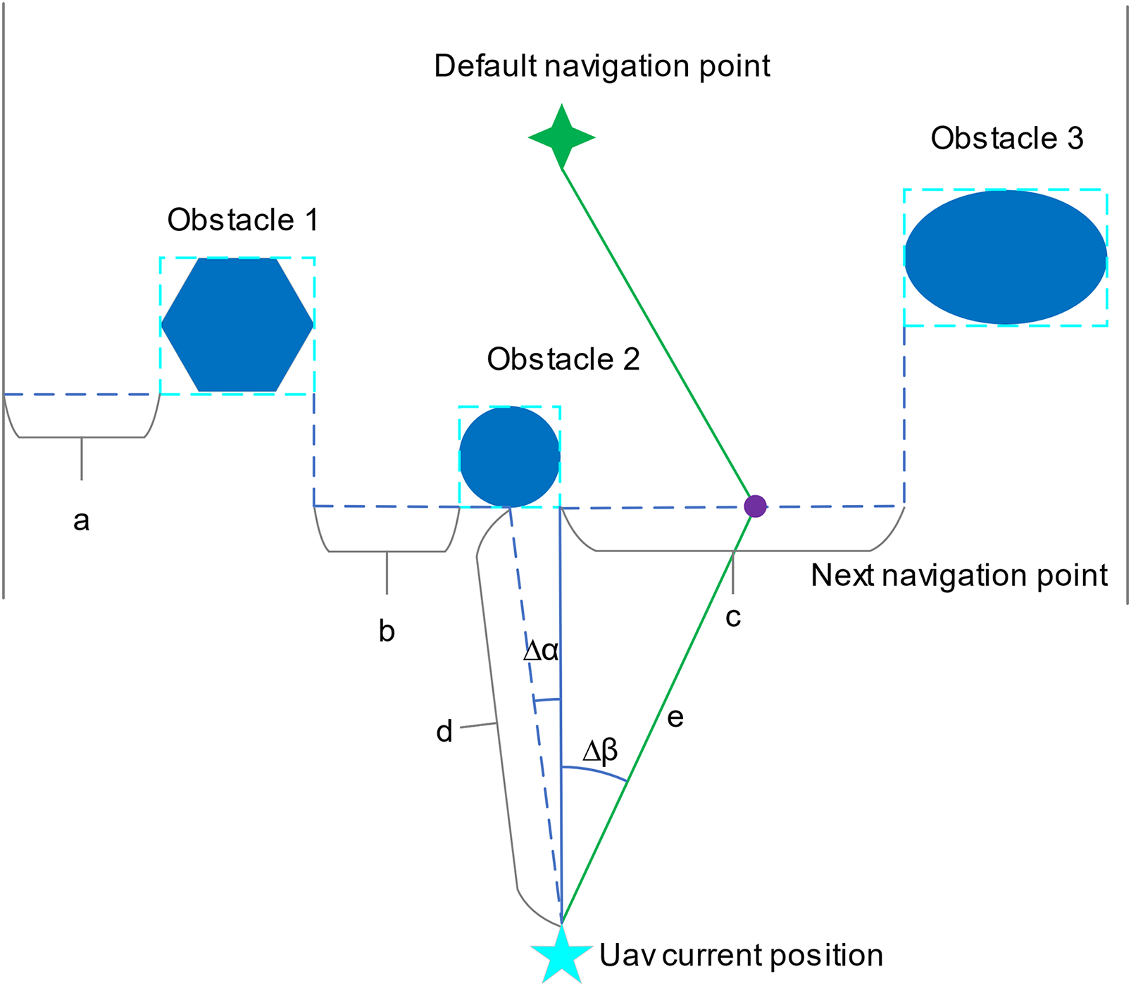
Figure 10: Schematic diagram of UAV obstacle avoidance based on action commands, shown in top view. a, b, c are the widths of the area where no obstacle is detected, c is the width corresponding to the area with the largest area, d is the distance from the UAV to the obstacle
Based on the obstacle distance as well as the focal length get the value of whether to go up or down next.
4 Experimental Results and Discussion
In this section, we evaluate UAD-YOLOv8 on the proposed UAD dataset and conduct comparisons with Gold-YOLO [14], YOLOv5, YOlOv6 [15], YOLOv7 [16], YOLOv8, YOLOv9 [17],and YOLOv10 [18]. Comprehensive ablation experiments are also conducted on the improvements of UAD-YOLOv8 relative to YOLOv8n, demonstrating the effectiveness of the improvements at each step. We also outline the specifics of the constructed UAD dataset and the details of the training process, and utilize the improved ranging method for obstacles at different distances as well as for obtaining obstacle avoidance commands through the visual obstacle avoidance algorithm.
Since there is no publicly available UAV obstacle dataset, in order to train and evaluate our designed network, we built a new high-quality UAV obstacle dataset. Specifically, our dataset consists of 3636 obstacle images taken in different seasons and environments. These images were taken by us or collected from the Internet. Considering the importance of accurate labeling for the target detection task, we manually labeled the UAD dataset in YOLO format using the LabelImg tool. We ensured high-quality and careful labeling despite the heavy occlusion of common obstacles and the small size of the targets. After labeling these 3636 images, we obtained 19,112 true bounding boxes.
To train UAD-YOLOv8, we divide the UAD dataset into training, validation and test sets according to 7:2:1, as illustrated in Table 1. In the dataset, there are different kinds of trees, different categories of poles, different colors and sizes of cars, and different postures of people. Since we are concerned with the task of detecting obstacles, they are subcategorized into one category. The UAD was used to train UAD-YOLOv8 in a variety of scenarios. In addition, in order to demonstrate our dataset more intuitively and clearly, example images of UAV obstacles in different scenarios are shown in Fig. 11.

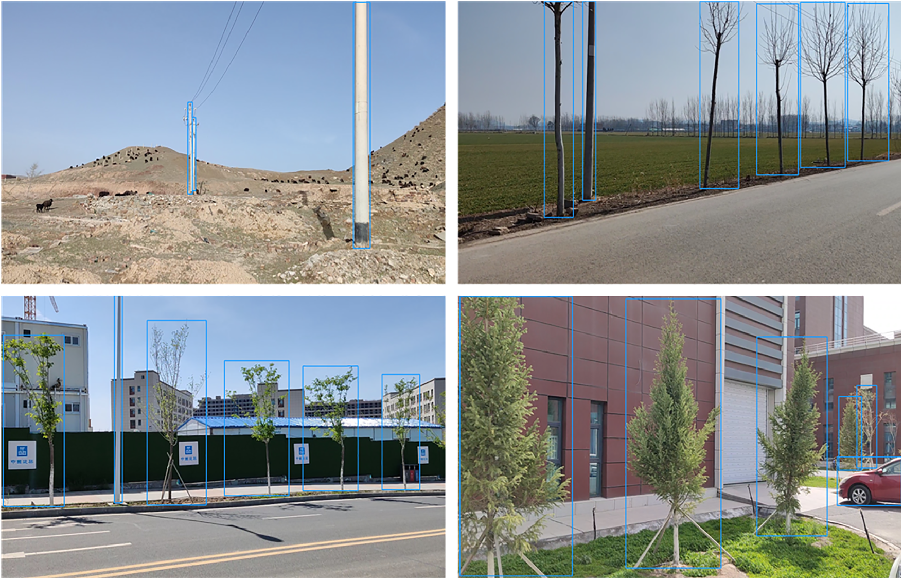
Figure 11: Examples of different scenarios with the UAD dataset, where the blue box indicates the obstacle true labeling box
Experiments were conducted to refine the YOLOv8n model with the help of the PyTorch 1.10 deep learning framework. All experiments were conducted on a server equipped with multiple Nvidia A40 graphics cards running Ubuntu 22.04.4 LTS. To optimize the model, the SGD optimizer was applied with an original learning rate of 0.01, a batch size of 8, and a total of 300 training epochs. The momentum parameter was set to 0.937, while the weight decay parameter was set to 0.0005.
To conduct a quantitative analysis of the performance of UAD-YOLOv8, we used mAP50 as the primary accuracy evaluation metric, and Parameters along with Giga Floating Point Operations (GFLOPs) as key metrics for lightweighting. To better demonstrate the performance improvements of UAD-YOLOv8 compared to baseline YOLOv8n and other YOLO versions, we also compared metrics such as Precision (P), Recall (R), F1-Score, mAP50-95, model size, and Frames Per Second (FPS).
Precision is defined by Eq. (16), and Recall is defined by Eq. (17). Precision and Recall have a tradeoff, which is balanced using the F1-Score, as shown in Eq. (18). Model size is critical for resource-limited device deployments, and FPS is used to measure model inference speed.
where TP represents true positive instances, FP represents false positive instances and FN represents false negative instances. N represents the number of species, AP represents Average Precision, and mAP represents mean Average Precision. The formula for mAP is provided in Eq. (19).
We tested UAD-YOLO on the UAD test set, Gold-YOLO [14], YOLOv5, YOLOv6 [15], YOLOv7 [16], YOLOv8, YOLOv9 [17] and YOLOv10 [18] were tested and published metrics for P, R, F1-Score, mAP50, mAP50-95, Parameters, Model Size, GFLOPs, and FPS. To ensure a fair comparison, all methods were trained on the UAD dataset under identical experimental conditions.
The results in Table 2 indicate that UAD-YOLOv8 has a smaller model size and fewer parameters compared to the other methods. The p-value of UAD-YOLOv8 is slightly lower than that of YOLOv5n, which is due to the deletion of the large-target feature extraction layer P5 in UAD-YOLOv8, but its mAP50 and mAP50-95 are higher than that of YOLOv5n. The mAP50-95 of our model is slightly lower than YOLOv9t, which is due to the reduced in computation. By introducing DCNv2 in C2f, DCNv2 adds computational and memory access overhead due to irregular sampling caused by offset, which reduces computing efficiency and thus inference speed, UAD-YOLOv8 still maintains real-time performance. UAD-YOLOv8 balances both precision and recall with an F1-Score of 0.771. UAD-YOLOv8 achieves a good parameter performance tradeoff, reaching 80.3 mAP50, with a parameter count of only 0.68 M.

To further validate the effectiveness of the proposed UAD-YOLOv8, we performed a comprehensive ablation study to analyze the different improved operations. We begin by building the base model, using the original YOLOv8n as the baseline for the detection network. The Backbone portion of the original YOLOv8n contains smaller resolution P5 feature layers, and the network employs a C2f module for feature fusion and larger detection head parameters. The improvement steps are shown below:
1) Base model + delete P5 feature layer + add C2f module after P1 feature layer → V1
2) All C2f modules in Base model are replaced with C2f-DCNv2 → V2
3) All C2f modules in V1 are replaced with C2f-DCNv2 → V3
4) The detection head in V3 is replaced with Lw-Detect, Layer 7 Conv is replaced with UGDConv1, and Layer 16 Conv is replaced with UGDConv2 → V4 (the complete model).
All of the models were retrained in the same manner and then tested on the UAD test set. As shown in Table 3, each improvement step in UAD-YOLOv8 contributes to target detection. A 1.1% mAP50 improvement relative to the base model is obtained by tweaking the network structure, and the number of parameters is reduced by about

Finally, it can be found that the network structure consisting of the improvements of all three operations has the best detection power, suggesting that the improvements of the three operations are complementary.
4.5 UAV Obstacle Detection and Obstacle Avoidance Command Acquisition
The effectiveness of the proposed adaptive distance detection algorithm based on obstacle attributes is further verified by performing distance calculations at different distances from the obstacles. The specific experimental data for distance measurement is presented in Table 4.

The data in Table 4 shows that the adaptive distance detection algorithm based on obstacle attributes can be used for distance detection in the UAV obstacle avoidance process. Through real-world testing, the drone can detect the distance to obstacles and output obstacle avoidance commands to avoid obstacles in the preset route.
In Fig. 12, (a) the center region overlapping with the obstacle exceeds the threshold value, but the distance from the drone to the obstacle is equal to or greater than the set value, and the flight continues. (b) The overlapping area exceeds the threshold value and the distance is within the set range of 6–10 m, fly slowly. (c) The overlapping area exceeds the threshold value, and the distance is less than 6 m, the UAV sets the area of the largest undetected obstacle as the area that can be safely flown, and gives the value of the yaw angle change, the upward value, and the value of advancement for the next step. (d) In cases corresponding to scenarios (c), a special case is encountered, the region of undetected obstacles is a wall, when the distance from the drone to the wall is close to 3 m, the command to hover and rotate 360° is given to avoid getting into trouble.
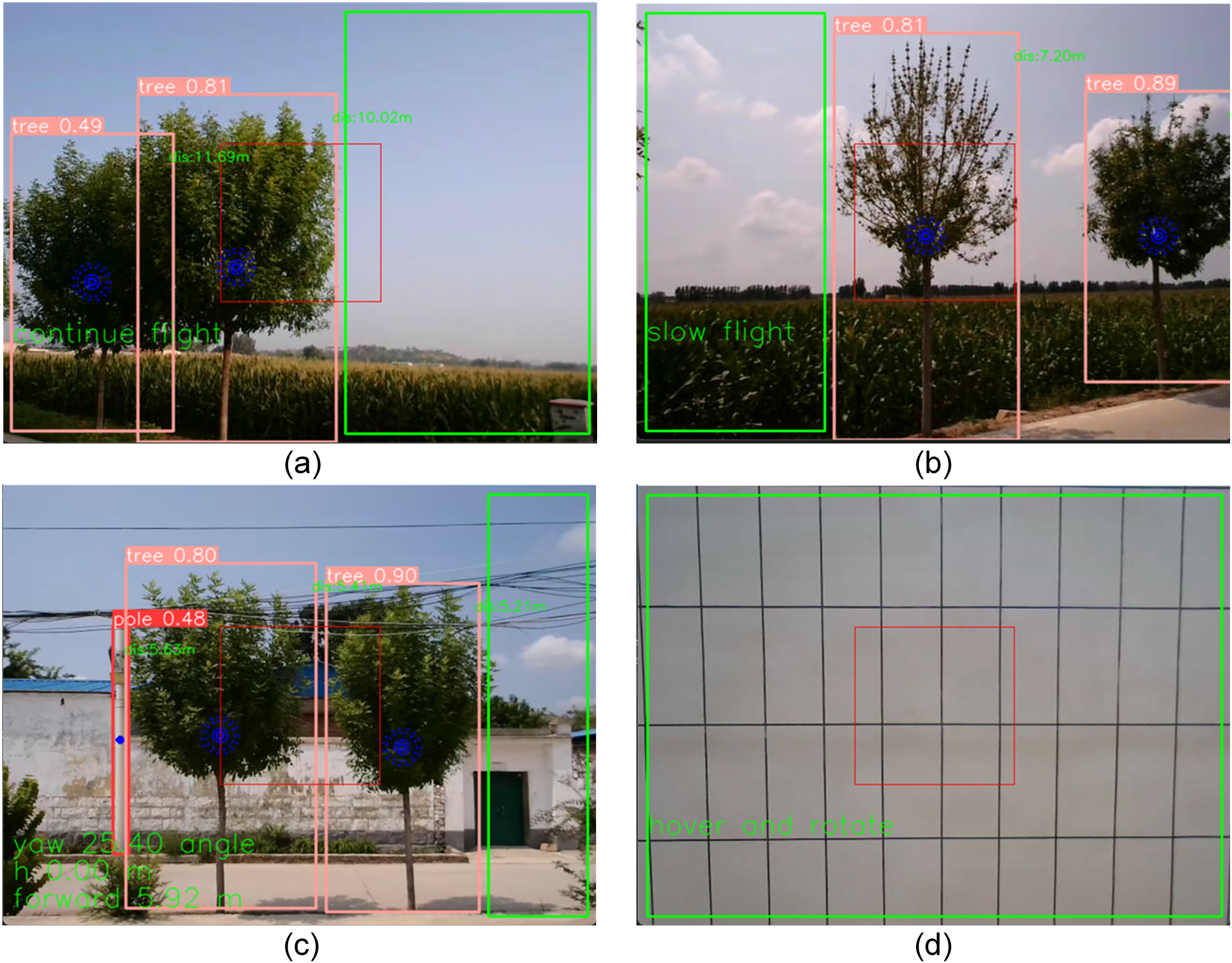
Figure 12: Real environment obstacle avoidance command acquisition. (a) Continuous flight command. (b) Slow flight command. (c) Next yaw angle and rise and forward command. (d) Hover and rotate commands. The blue points are the pixel points taken in the adaptive distance detection algorithm based on obstacle attributes. The red box area is the center area of the setup, and the green area is the maximum undetected obstacle area
In this work, we build a high-quality UAV obstacle dataset for UAV obstacle recognition. We propose a lightweight obstacle detection network, UAD-YOLOv8, for automatic detection of obstacles that may be encountered in UAVs flying at low altitude.
To address the issue of detecting small target obstacles and irregular obstacles in jittery images from the UAV viewpoint, we replace C2f with the C2f-DCNv2 module. Additionally, in order to minimize the quantity of network parameters as well as the model size, the network structure is adjusted, the UGDConv series of modules are constructed and used in the network structure, and a lightweight detection head is employed to substitute the original one. In addition, we designed a lightweight UAV visual obstacle avoidance algorithm based on the proposed UAD-YOLOv8. In visual obstacle distance detection, we propose an adaptive distance detection algorithm based on obstacle attributes, and we design specific obstacle avoidance strategies for situations encountered by UAVs flying at low altitude. Finally, extensive evaluations show that our UAD-YOLOv8 performs well and the visual obstacle avoidance algorithm can accurately obtain the next flight instructions.
In future work, we plan to explore more effective obstacle detection and UAV obstacle avoidance algorithms by fusing vision sensors with other sensors. Also we will further increase the variety of obstacles in the dataset to reduce the limitations of the algorithms. Since vision-based UAV obstacle avoidance algorithms are affected in both bright and low light situations, combining the advantages of multiple sensors can realize complementary data, for example, combining vision sensors with lightweight LIDAR to reduce the impact of light changes, further enhancing the UAV’s ability to perceive the external environment and thus realizing UAV obstacle avoidance in a variety of complex situations. UAV obstacle avoidance algorithms can improve the safety and reliability of low-altitude inspection and logistics distribution tasks in the real world. Our UAV visual obstacle avoidance algorithms still have limitations in real-world applications. Multi-sensor data fusion can enable UAVs to operate under different lighting conditions and detect obstacles with high accuracy in emergency response situations such as search and aid missions, which is critical for timely and safe mission execution.
Acknowledgement: This work was supported by Xinjiang Uygur Autonomous Region Metrology and Testing Institute and Tianshan Talent Training Project–Xinjiang Science and Technology Innovation Team.
Funding Statement: This work was supported by Xinjiang Uygur Autonomous Region Metrology and Testing Institute Project (Grant No. XJRIMT2022-5) and Tianshan Talent Training Project–Xinjiang Science and Technology Innovation Team Program (2023TSYCTD0012).
Author Contributions: The authors confirm contribution to the paper as follows: study conception and design: Zongdong Du, Zhenhong Jia, Xuefeng Feng; data collection: Zongdong Du, Feng Li, Qinglong Xian; analysis and interpretation of results: Zongdong Du, Xuefeng Feng, Feng Li; draft manuscript preparation: Zongdong Du, Zhenhong Jia. All authors reviewed the results and approved the final version of the manuscript.
Availability of Data and Materials: The UAD dataset is available at the link below https://drive.google.com/file/d/1X0KVrlNxHznbQTy0c3aelDLHGorEEfO5/view?usp=sharing (accessed on 24 September 2024).
Ethics Approval: Not applicable.
Conflicts of Interest: The authors declare that they have no conflicts of interest to report regarding the present study.
References
1. D. Vera-Yanez, A. Pereira, N. Rodrigues, J. P. Molina, A. S. García and A. Fernández-Caballero, “Optical flow-based obstacle detection for mid-air collision avoidance,” Sensors, vol. 24, no. 10, May 2024, Art. no. 3016. doi: 10.3390/s24103016. [Google Scholar] [PubMed] [CrossRef]
2. Y. Wang, J. Liu, J. Wang, Q. Zeng, X. Shen and Y. Zhang, “Micro aerial vehicle navigation with visual-inertial integration aided by structured light,” J. Navig., vol. 73, no. 1, pp. 16–36, Jan. 2020. doi: 10.1017/S0373463319000511. [Google Scholar] [CrossRef]
3. G. Capi, N. Sugiyama, and S. Kaneko, “Application of deep learning for drone obstacle avoidance and goal directed navigation,” in 2021 Int. Conf. Ubiquitous Robots (UR), Gangneung, Republic of Korea, Jul. 12–14, 2021, pp. 453–457. [Google Scholar]
4. X. Dai, Y. Mao, T. Huang, N. Qin, D. Huang and Y. Li, “Automatic obstacle avoidance of quadrotor UAV via CNN-based learning,” Neurocomputing, vol. 402, no. 5, pp. 346–358, Apr. 2020. doi: 10.1016/j.neucom.2020.04.020. [Google Scholar] [CrossRef]
5. M. S. Akremi, N. Neji, and H. Tabia, “Visual navigation of uavs in indoor corridor environments using deep learning,” in 2023 Integr. Commun. Navig. Surveill. Conf. (ICNS), Herndon, VA, USA, Apr. 18–20, 2023, pp. 1–6. [Google Scholar]
6. M. Mancini, G. Costante, P. Valigi, and T. A. Ciarfuglia, “J-MOD2: Joint monocular obstacle detection and depth estimation,” IEEE Robot. Autom. Lett., vol. 3, no. 3, pp. 1490–1497, Jan. 2018. doi: 10.1109/LRA.2018.2800083. [Google Scholar] [CrossRef]
7. Z. Zhang, M. Xiong, and H. Xiong, “Monocular depth estimation for UAV obstacle avoidance,” in 2019 4th Int. Conf. Cloud Comput. Internet Things (CCIOT), Tokyo, Japan, Sep. 20–22, 2019, pp. 43–47. [Google Scholar]
8. X. Dai, Y. Mao, T. Huang, N. Qin, D. Huang and Y. Li, “Reactive obstacle avoidance of monocular quadrotors with online adapted depth prediction network,” Neurocomputing, vol. 325, no. 3, pp. 142–158, Jan. 2019. doi: 10.1016/j.neucom.2018.10.019. [Google Scholar] [CrossRef]
9. N. Shen, J. Cao, M. Zipp, and W. Stork, “Autonomous obstacle avoidance for UAV based on point cloud,” in 2022 Int. Conf. Unmanned Aircraft Syst. (ICUAS), Dubrovnik, Croatia, Jun. 21–24, 2022, pp. 1580–1585. [Google Scholar]
10. Z. Xue and T. Gonsalves, “Vision based drone obstacle avoidance by deep reinforcement learning,” AI, vol. 2, no. 3, pp. 366–380, Aug. 2021. doi: 10.3390/ai2030023. [Google Scholar] [CrossRef]
11. A. P. Kalidas, C. J. Joshua, A. Q. Md, S. Basheer, S. Mohan and S. Sakri, “Deep reinforcement learning for vision-based navigation of UAVs in avoiding stationary and mobile obstacles,” Drones, vol. 7, no. 4, Apr. 2023, Art. no. 245. doi: 10.3390/drones7040245. [Google Scholar] [CrossRef]
12. D. S. Levkovits-Scherer, I. Cruz-Vega, and J. Martinez-Carranza, “Real-time monocular vision-based UAV obstacle detection and collision avoidance in GPS-denied outdoor environments using CNN MobileNet-SSD,” in Adv. Soft Comput.: 18th Mex. Int. Conf. Artif. Intell., MICAI 2019, Xalapa, Mexico, Oct. 27–Nov. 2, 2019, pp. 613–621. [Google Scholar]
13. H. Y. Lee, H. W. Ho, and Y. Zhou, “Deep learning-based monocular obstacle avoidance for unmanned aerial vehicle navigation in tree plantations: Faster region-based convolutional neural network approach,” J. Intell. Robot. Syst., vol. 101, no. 1, Dec. 2021, Art. no. 5. doi: 10.1007/s10846-020-01284-z. [Google Scholar] [CrossRef]
14. C. Wang et al., “Gold-YOLO: Efficient object detector via gather-and-distribute mechanism,” in Adv. Neural. Inf. Process. Syst., New Orleans, LA, USA, Dec. 10–16, 2023. [Google Scholar]
15. C. Li et al., “YOLOv6 v3.0: A full-scale reloading,” 2023, arXiv:2301.05586. [Google Scholar]
16. C. Wang, A. Bochkovskiy, and H. Liao, “YOLOv7: Trainable bag-of-freebies sets new state-of-the-art for real-time object detectors,” in Proc. IEEE/CVF Conf. Comput. Vis. Pattern Recognit, Vancouver, BC, Canada, Jun. 17–24, 2023, pp. 7464–7475. [Google Scholar]
17. C. -Y. Wang, I. -H. Yeh, and H. -Y. M. Liao, “YOLOv9: Learning what you want to learn using programmable gradient information,” 2024, arXiv:2402.13616. [Google Scholar]
18. A. Wang et al., “YOLOv10: Real-time end-to-end object detection,” 2024, arXiv:2405.14458. [Google Scholar]
19. Z. Zhang, “Drone-YOLO: An efficient neural network method for target detection in drone images,” Drones, vol. 7, no. 8, Aug. 2023, Art. no. 526. doi: 10.3390/drones7080526. [Google Scholar] [CrossRef]
20. N. U. A. Tahir, Z. Long, Z. Zhang, M. Asim, and M. ELAffendi, “PVswin-YOLOv8s: UAV-based pedestrian and vehicle detection for traffic management in smart cities using improved YOLOv8,” Drones, vol. 8, no. 3, Feb. 2024, Art. no. 84. doi: 10.3390/drones8030084. [Google Scholar] [CrossRef]
21. Z. Fu, Y. Xiao, F. Tao, P. Si, and L. Zhu, “DLSW-YOLOv8n: A novel small maritime search and rescue object detection framework for UAV images with deformable large kernel net,” Drones, vol. 8, no. 7, Jul. 2024, Art. no. 310. doi: 10.3390/drones8070310. [Google Scholar] [CrossRef]
22. T. Zhang, X. Hu, J. Xiao, and G. Zhang, “A machine learning method for vision-based unmanned aerial vehicle systems to understand unknown environments,” Sensors, vol. 20, no. 11, Jun. 2020, Art. no. 3245. doi: 10.3390/s20113245. [Google Scholar] [PubMed] [CrossRef]
23. X. She, D. Huang, C. Song, N. Qin, and T. Zhou, “Multi-obstacle detection based on monocular vision for UAV,” in 2021 IEEE 16th Conf. Industr. Electron. Appl. (ICIEA), Chengdu, China, Aug. 1–4, 2021, pp. 1067–1072. [Google Scholar]
24. D. Wang, W. Li, X. Liu, N. Li, and C. Zhang, “UAV environmental perception and autonomous obstacle avoidance: A deep learning and depth camera combined solution,” Comput. Electron. Agric., vol. 175, no. 3–4, Aug. 2020, Art. no. 105523. doi: 10.1016/j.compag.2020.105523. [Google Scholar] [CrossRef]
25. T. N. Canh, A. Elibol, N. Y. Chong, and X. HoangVan, “Object-oriented semantic mapping for reliable UAVs navigation,” in 2023 12th Int. Conf. Control Autom. Inf. Sci. (ICCAIS), Hanoi, Vietnam, Nov. 27–29, 2023, pp. 139–144. [Google Scholar]
26. J. Liu, Y. Yan, Y. Yang, and J. Li, “An improved artificial potential field UAV path planning algorithm guided by RRT under environment-aware modeling: Theory and simulation,” IEEE Access, vol. 12, no. 3, pp. 12080–12097, Jan. 2024. doi: 10.1109/ACCESS.2024.3355275. [Google Scholar] [CrossRef]
27. B. Ma et al., “Using an improved lightweight YOLOv8 model for real-time detection of multi-stage apple fruit in complex orchard environments,” Artif. Intell. Agric., vol. 11, no. 4, pp. 70–82, Mar. 2024. doi: 10.1016/j.aiia.2024.02.001. [Google Scholar] [CrossRef]
28. P. Du and X. Song, “Lightweight target detection: An improved YOLOv8 for small target defect detection on printed circuit boards,” in 2024 Int. Conf. Generative Artif. Intell. Inf. Security, Kuala Lumpur, Malaysia, May 10–12, 2024, pp. 329–334. [Google Scholar]
29. Z. Huangfu and S. Li, “Lightweight you only look once v8: An upgraded you only look once v8 algorithm for small object identification in unmanned aerial vehicle images,” Appl. Sci., vol. 13, no. 22, Nov. 2023, Art. no. 12369. doi: 10.3390/app132212369. [Google Scholar] [CrossRef]
30. M. Yue, L. Zhang, J. Huang, and H. Zhang, “Lightweight and efficient tiny-object detection based on improved YOLOv8n for UAV aerial images,” Drones, vol. 8, no. 7, Jun. 2024, Art. no. 276. doi: 10.3390/drones8070276. [Google Scholar] [CrossRef]
31. X. Zhu, H. Hu, S. Lin, and J. Dai, “Deformable convnets v2: More deformable, better results,” in Proc. IEEE/CVF Conf. Comput. Vis. Pattern Recognit, Long Beach, CA, USA, Jun. 15–20, 2019, 9308–9316. [Google Scholar]
32. K. Han, Y. Wang, Q. Tian, J. Guo, C. Xu and C. Xu, “GhostNet: More features from cheap operations,” in Proc. IEEE/CVF Conf. Comput. Vision Pattern Recognit, Seattle, WA, USA, Jun. 13–19, 2020, 1580–1589. [Google Scholar]
33. A. G. Howard et al., “MobileNets: Efficient convolutional neural networks for mobile vision applications,” 2017, arXiv:1704.04861. [Google Scholar]
34. A. Krizhevsky, I. Sutskever, and G. E. Hinton, “ImageNet classification with deep convolutional neural networks,” in Adv. Neural Inf. Process. Syst., Lake Tahoe, NV, USA, 2012, vol. 25. [Google Scholar]
35. H. Hirschmuller, “Accurate and efficient stereo processing by semi-global matching and mutual information,” in 2005 IEEE Comput. Soc. Conf. Comput. Vis. Pattern Recognit. (CVPR’05), San Diego, CA, USA, Jun. 20–25, 2005, pp. 807–814. [Google Scholar]
Cite This Article
 Copyright © 2024 The Author(s). Published by Tech Science Press.
This work is licensed under a Creative Commons Attribution 4.0 International License , which permits unrestricted use, distribution, and reproduction in any medium, provided the original work is properly cited.


 Submit a Paper
 Propose a Special lssue
 View Full Text
 Download PDF
 Downloads
 Citation Tools