 Open Access
ARTICLE
Fuzzy Control Optimization of Loading Paths for Hydroforming of Variable Diameter Tubes
1 College of Metallurgy and Energy, North China University of Science and Technology, Tangshan, 063210, China
2 Shi-Changxu Innovation Center for Advanced Materials, Institute of Metal Research, Chinese Academy of Sciences, Shenyang, 110000, China
3 Shenyang Duoyuan Mechanical & Electrical Equipment Co., Ltd., Shenyang, 110000, China
* Corresponding Author: Wenlong Xie. Email:
(This article belongs to the Special Issue: Emerging Trends in Fuzzy Logic)
Computers, Materials & Continua 2024, 81(2), 2753-2768. https://doi.org/10.32604/cmc.2024.055408
Received 26 June 2024; Accepted 14 September 2024; Issue published 18 November 2024
Abstract
The design of the loading path is one of the important research contents of the tube hydroforming process. Optimization of loading paths using optimization algorithms has received attention due to the inefficiency of only finite element optimization. In this paper, the hydroforming process of 5A02 aluminum alloy variable diameter tube was as the research object. Fuzzy control was used to optimize the loading path, and the fuzzy rule base was established based on FEM. The minimum wall thickness and wall thickness reduction rate were determined as input membership functions, and the axial feeds variable value of the next step was used as output membership functions. The results show that the optimized loading path greatly improves the uniformity of wall thickness and the forming effect compared with the linear loading path. The round corner lamination rate of the tube is 91.2% under the fuzzy control optimized loading path, which was increased by 47.1% and 22.6% compared with linear loading Path 1 and Path 2, respectively. Based on the optimized loading path in the experiment, the minimum wall thickness of the variable diameter tube was 1.32 mm and the maximum thinning rate was 12.4%. The experimental results were consistent with the simulation results, which verified the accuracy of fuzzy control. The research results provide a reference for improving the forming quality of thin-walled tubes and plates.Keywords
The tube hydroforming process is a kind of processing technology using liquid as a pressure transmitting medium to form complex tube parts. It has the advantages of reducing the weight of parts, and improving material utilization and structural strength and stiffness [1,2]. The matching relationship between the internal liquid pressure and the axial feeds, that is, the loading path, is crucial in the tube hydroforming process. Forming defects such as wrinkling, buckling, and cracking are easy to occur when the loading path is not suitable [3,4]. Therefore, it is of great significance to optimize the loading path of the tube hydroforming process. Two kinds of optimization methods, including the adaptive feeds method and optimization algorithm based on optimization [5,6], are often used in loading path optimization of the tube hydroforming process.
Aue-U-Lan et al. [7] proposed a self-feeding optimization method based on experimental results, which was mainly used to determine the natural relationship between internal pressure and axial feed and the adjustment coefficient. The advantage of this method is that a relatively reasonable loading curve can be obtained quickly. However, it lacked sufficient theoretical support and was only applicable to straight shaft type tube parts with simple morphology. Yang et al. [8] used the degree of uniformity in tube wall thickness distribution as the objective function and film-forming adhesion as the constraint function, and a set of loading path parameters was summarized to guide the hydroforming process after sensitivity analysis of node variables. Lorenzo et al. [9] adopted the most rapid descent method to optimize the loading path, in which the expansion height of the branch tube was an objective function. By comparing the results of the static iteration method and dynamic iteration method, a more optimized dynamic iteration method is derived. Di Lorenzo et al. [10] optimized the matching relationship between internal pressure and axial feeds using a genetic algorithm. The maximum displacement forming limit diagram of the feature point was used as a fracture evaluation index. Mohammadi et al. [11] proposed a calibration indicator for crack prediction, which was applied to increase the axial feeds and decrease the internal pressure during hydroforming. By communicating with the kernel function of software and fuzzy controller, the effect of the loading path was analyzed and it was found that necking was an irreversible defect and wrinkling was a repairable defect. Manabe et al. [12] proposed a “virtual control system” that includes fuzzy algorithms and evaluation functions. A new evaluation function for the flexion of the shoulder of the T-type tee tube branch and the contact of the counter-convex die was proposed. A new fuzzy control path was obtained by using a virtual control system.
The loading path optimization based on gradient or evolutionary algorithms also has certain drawbacks, for example, it is difficult to obtain the globally optimal loading paths, and the optimization process requires a large amount of time and cost. Fuzzy control is an intelligent and nonlinear control method. Zhang et al. [13] used an inverse model to capture the output lag phenomenon and solved the problem of adaptive fuzzy rule-defined time tracking for nonlinear systems with output lags. An adaptive fuzzy control scheme based on an inverse-step framework was proposed by using a predefined time-stability criterion. Cui et al. [14] developed an adaptive fixed-time tracking control strategy by using fuzzy control combined with dynamic surface techniques and inverse stepping methods. In addition, an improved mode-dependent average dwell-time switching rule was also introduced to ensure the stability of switched nonlinear systems with unstable subsystems. Teng et al. [15] used an adaptive simulation method combined with a fuzzy control algorithm to optimize the loading path of T-tube hydroforming in order to avoid wrinkling. In this paper, an adaptive simulation method based on fuzzy control combined with finite element simulation was proposed in this paper. The object of loading path optimization was the variable diameter tube hydroforming process [16,17]. The fuzzy control process simulation was achieved by using the fuzzy controller, where the fuzzy rule base was based on engineering experience. The inputs of the control system were extracted directly from the finite element software and processed by the fuzzy controller. The resulting outputs were used as inputs for the finite element simulation, enabling the data exchange between fuzzy control and hydraulic forming process feedback. The optimized loading paths were obtained, which can reduce the risk of wrinkling or cracking. The research results provide a reference for improving the forming quality of thin-walled tubes and plates [18].
2 Experimental Materials and Method
In this paper, 5A02 aluminum alloy tube was used as the research object, the mechanical property parameters are shown in Table 1. The initial outer diameter D of the tube was 45 mm and the wall thickness was 1.5 mm.

Hydroforming equipment and forming molds are shown in Fig. 1, The equipment is 315t special hydraulic molding equipment, driven by servo motors, which not only has low energy consumption, low noise, but also has high control precision. The experimental equipment utilizes PLC control to achieve pressure, speed, and displacement servo-proportional numerical control. The equipment also allows for real-time display and modification of the pressure and displacement of the push head. The forming die mainly consists of left and right push heads, upper and lower dies, and the experimental process uses tensile oil as a lubricant between the tube and the die. The target molding dimensions are shown in Fig. 2. The initial outer diameter

Figure 1: Servo hydroforming equipment and molds
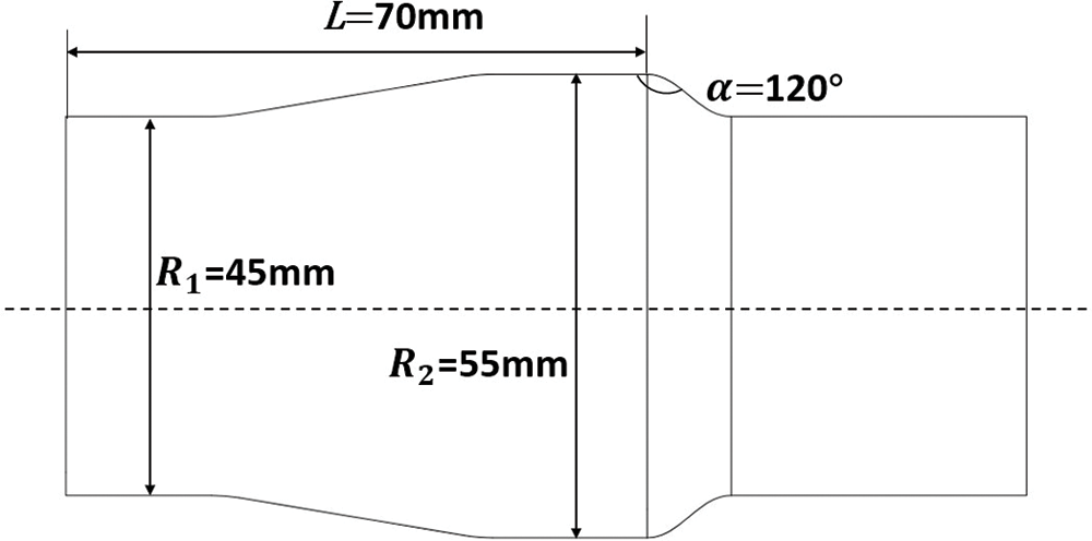
Figure 2: Schematic of the dimensions of the target molded part
There are many factors that affect the forming quality of variable diameter tube during hydroforming. Therefore, it is necessary to numerically simulate and analyze the forming process of tube in order to determine the factors affecting the forming results of variable diameter tube, and at the same time to reduce the material waste and time cost caused by a large number of experiments. In the fuzzy control, the wall thickness and its change rate at the maximum thinning of the bulging zone of the tube are needed as input functions, but it is difficult to obtained through the sensor in the experiment. Therefore, the wall thickness distribution and the rate of wall thickness change for each work step from the post-processed are obtained from the finite element simulation. According to the actual forming device, the simulation model is established as shown in Fig. 3. The tube material was a 5A02 aluminum alloy tube used as the initial outer diameter of 45 mm, a wall thickness of 1.5 mm, and a length of 145 mm, mechanical properties are listed in Table 1. The pressure in the axial feeds direction is directly applied to the end of the tube, which aims to simplify the simulation model for the convenience of feeds, approximate to 1 mm tube grid size, grid type for tetrahedron grid, grid cell properties for S4R. The hydraulic die is set as a free constraint, the tube property is set as a deformable body, the length of the deformable zone is 12 mm, and the dynamic friction factor coefficient between the tube and the die is set to 0.1 [19,20].
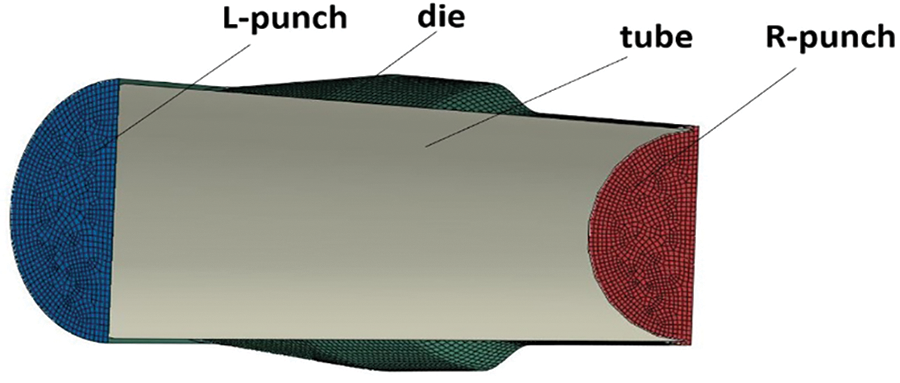
Figure 3: Finite element model
Fuzzy control is a kind of computer digital control technology based on fuzzy set theory, fuzzy linguistic variables and fuzzy logic reasoning. The advantage is that there is no need to build an accurate mathematical model to solve the engineering problem. Only a simple understanding of the specific influencing factors of the control variable on the controlled variable is required, which is often referred to as expert experience, mainly applied to solve real can’t use a specific mathematical model to solve the problem [21].
The core of fuzzy control is fuzzy controller, which is mainly composed of four parts: fuzzy rule base, fuzzy inference rule, input fuzzification and output defuzzification [15]. The control flow chart of loading paths optimization using fuzzy control method is shown in Fig. 4.
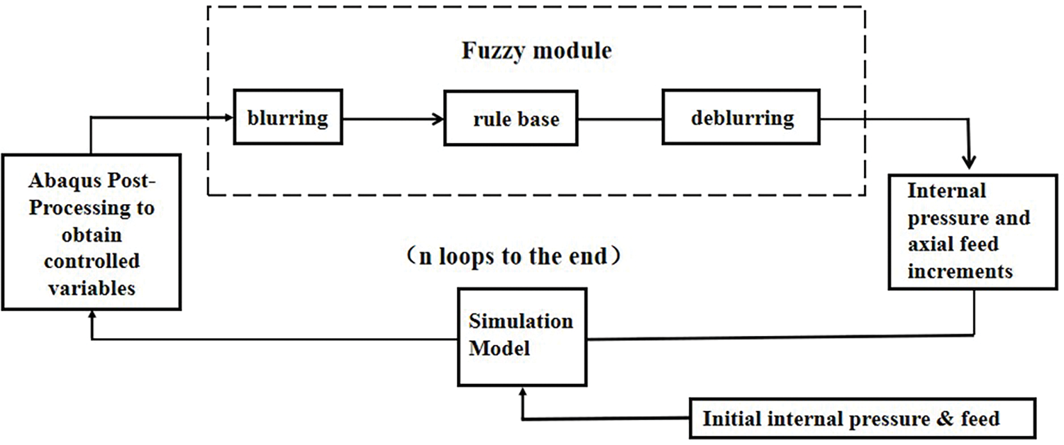
Figure 4: Loading paths loop control block diagram
The loading paths of the whole process of variable diameter tube hydroforming is divided into several separate loading steps to keep the internal pressure linear loading paths unchanged. The axial feeds rate has a great influence on the wall thickness variation of the tube. The simulation is carried out under the given initial internal pressure and feeds rate, and the required controlled variable results are obtained from the post-processing results, which are used as the input of the controller. Under the rules of the controller internal library core decision-making, the decision-making after the output is the next step loading of the axial feeds. This result is then used to simulate the next loading step and repeat the loop until the shaping is complete.
3.2 Entering Membership Function
For the selected research object, the most likely forming defect is rupture in the bulging zone, which is also the most serious place of tube hydroforming thinning, it can also reflect the distribution of wall thickness variation during the whole hydroforming stage. Therefore, the maximum thinning of bulging region is selected as the reference basis for fuzzy control research.
The minimum wall thickness of bulging zone in the hydroforming process of variable diameter tube is selected as the input membership function E, and the thickness change rate at this point is selected as the input membership function EC, the formula is as follows:
where
Change rate of the bulging zone extracted from the Abaqus finite element simulation are input into the fuzzy controller as parameter variables, that is the process of fuzzification of the variables. According to the relevant standards of hydroforming, the maximum thinning rate of more than 20% is considered as a defect leading to forming failure. The domain of discourse of input membership function
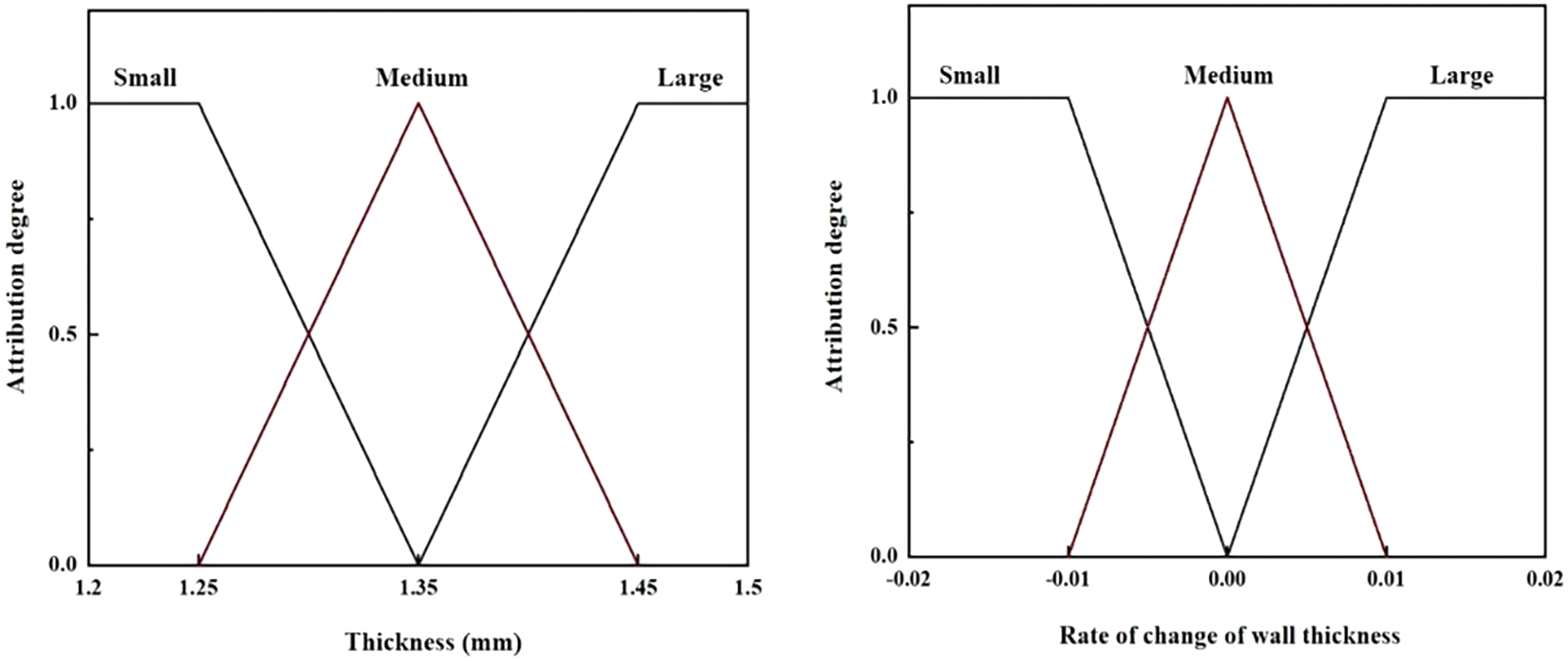
Figure 5: Inputting membership functions
where
The minimum thickness of the forming result of the variable diameter tube is selected as the optimization target, and the linear loading mode of the internal pressure is selected. The maximum pressure is taken as 44 MPa, the loading time is 10 s, and the output of the fuzzy control is the axial feeds. As the pressure inside the tube increases, it rapidly enters the stage of plastic deformation. With the continuous increase of internal pressure, the wall thickness of the bulging zone of the tube decreases continuously. In order to avoid the rupture of the side wall caused by the excessive change of internal pressure, it is necessary to feeds the axial feeds at the right end to increase the fluidity of the material in the bulging area and improve the bulging height. The minimum wall thickness and the rate of wall thickness change in the bulging zone are selected as the two inputs of the controller. According to the input membership function mentioned above, the minimum wall thickness of the input variable and the wall thickness change rate are divided into three levels of “small, medium and large”, and the axial feeds amount of the output variable is also divided into these three levels. The division of fuzzy intervals directly affects the control accuracy, the more fuzzy intervals are divided, the more accurate the controller is, but the disadvantage is that the number of fuzzy rules increases exponentially, which makes the design of control rules difficult. Considering the efficiency and accuracy of operation comprehensively, the input and output variables are divided into “small, medium and large” three levels [15].
The specific fuzzy rules are shown in Table 2. For example: for the first table in the upper left corner of the table, if the input

3.4 The Outputing Membership Function
In this paper, the center of gravity calculation method is selected for defuzzification, and the output obtained is a collection of several exact quantities. The center of gravity method is calculated as shown in Formula (4). Fig. 6 shows the output dependency function of the axial feeds increment “
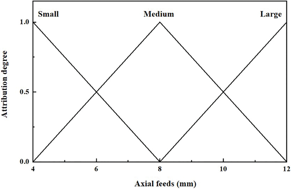
Figure 6: Outputting membership functions μ
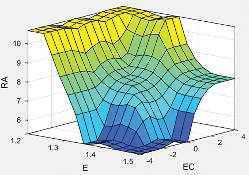
Figure 7: Fuzzy controller feature surface
where
4.1 Influence of Main Process Parameters on Molding Quality
For hydroforming of variable diameter tube, the matching relationship between left and right punch, friction coefficient and internal pressure are important factors in determining the loading paths. For 5A02 variable diameter tube forming, the internal pressure linear loading method is used to pressurize, and the axial feeds rate is constantly changed to shape the target tube fitting. For axisymmetric parts, Formulas (5) and (6) can be used to estimate the initial yield pressure
where
The specific loading paths design includes applying a uniform distribution of liquid pressure on the inner wall of the line, the right end of the tube is fed by unidirectional feeding, and the left end is fixed to carry out hydraulic bulging of the tube. The designed liquid pressure action time is 10 s in total, within 0∼8 s, the hydraulic pressure adopted the linear loading method, the axial feeding amount adopted the uniform feeding for the replenishment, after 8 s, the system entered the pressure holding state and stopped feeding until the forming was finished. The hydraulic pressure rise curve was divided into initial yield pressure

Figure 8: Maximum thinning of bulging zone under three different pressures (simulation)
The simulation result shows that on the premise of bulging pressure is constant, with the increase of axial feeding, tube bulging area maximum thinning and decreases. At the initial yield pressure when the axial charge is too large and the internal pressure is too small due to the fluidity of the material will eventually lead to the accumulation of material buckling and other material defects results as shown in Fig. 9 when the internal pressure is too large and the feeds is not enough, there is not enough time axis feeds in the hydraulic forming process, resulting in material defects such as cracking, and the final model is also in the state of uncoated.

Figure 9: Thickness distribution diagram: internal pressure of 10 MPa and axial feeds rate of 12 mm as shown in (a). Internal pressure of 40 MPa and axial feeds rate of 4 mm as shown in (b)
Therefore, the hydroforming process of tube is a dynamic process changing with time, and an accurate mathematical model or simple quantitative function cannot be used to accurately express the relationship between internal pressure and axial feeds rate. Based on the optimization simulation method based on fuzzy control combined with adaptive simulation proposed in this paper, the variable diameter tube is taken as the research object. The simulation of fuzzy control process is realized by fuzzy controller and the optimal process matching relationship between the internal pressure and the feeding amount is obtained, reduce tube wrinkling and cracking defects, to optimize the loading paths.
4.2 Applications of Fuzzy Control
Minimum wall thickness in the expansion zone of the reducer and fillet lamination rate as a measure of how well the reducer was formed. One aspect of optimizing tube hydroforming was achieved in the process of hydroforming tube in the mold rounded area of the final film state, the specific area as shown in Fig. 10. This was calculated by taking the ratio of the longitudinal distance of the model at the fillet to the distance of the mold in that direction as the fitting ratio at the fillet for the fitting. Specific calculation as shown in Formula (7):
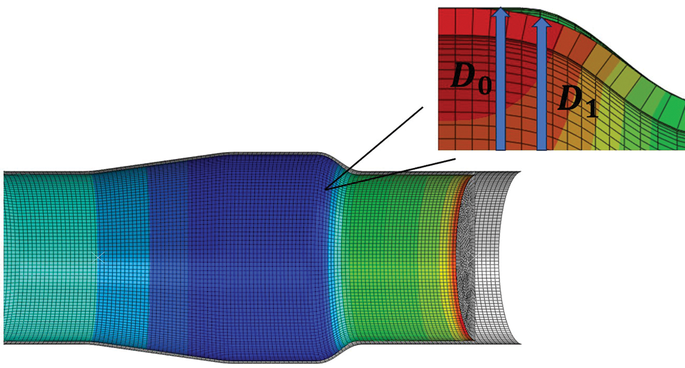
Figure 10: Unfitting area of rounded corners
where
To facilitate a more intuitive comparison of the fuzzy control optimization based on the effect of variable diameter tube forming, simulation results of variable diameter tubes under three loading paths were compared. Since the higher the pressure, the better the effect of tube fitting the forming die, the internal pressure was selected as 44 MPa considering the simulation results (Fig. 9) and the bearable pressure of the equipment. To achieve the thinning less than 0.2 mm, the feed ranges of 8.5 mm and 12.5 mm were selected. Within the parameter range, the optimized load path and linear path were shown in Fig. 11. From the Fig. 11, it can be seen that the loading paths of internal pressure and axial feeds optimized based on fuzzy control is the curve.
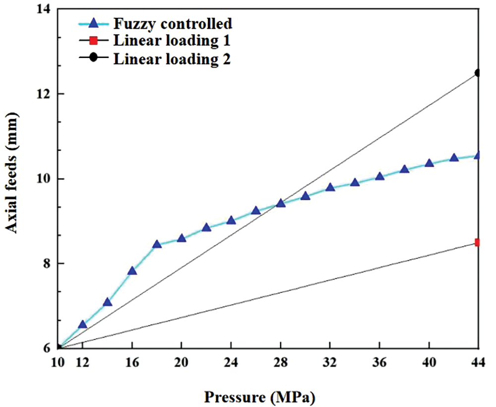
Figure 11: Axial feeds for three loading paths
Compared with linear loading Path 1 and linear loading Path 2, the loading path form fuzzy control optimization algorithm improved the accuracy of the filleting rate of rounded corners. The round corner lamination rate of the tube after fuzzy control optimization is 91.2%, while round corner lamination rate of linear loading Path 1 and Path 2 was 62% and 74.4%, and significantly improved by 47.1% and 22.6%, respectively.
Comparison of the molding effect under the three loading paths is shown in Fig. 12. During the initial loading phase, the rate of axial feeds growth exceeds that of internal pressure due to the tube’s recent plastic deformation. This requires a significant amount of feeds to achieve the film state. In the later stages of the loading paths, the axial feeds growth rate slows down compared to the earlier stages. This is because the model has already reached the film state and requires greater pressure for pressure-holding and shaping to achieve the final molding state. The simulation results obtained through fuzzy control optimization improve the uniformity of the wall thickness distribution of the tube under the loading paths compared to linear loading. The wall thickness distribution for the three loading paths is shown in Fig. 13.
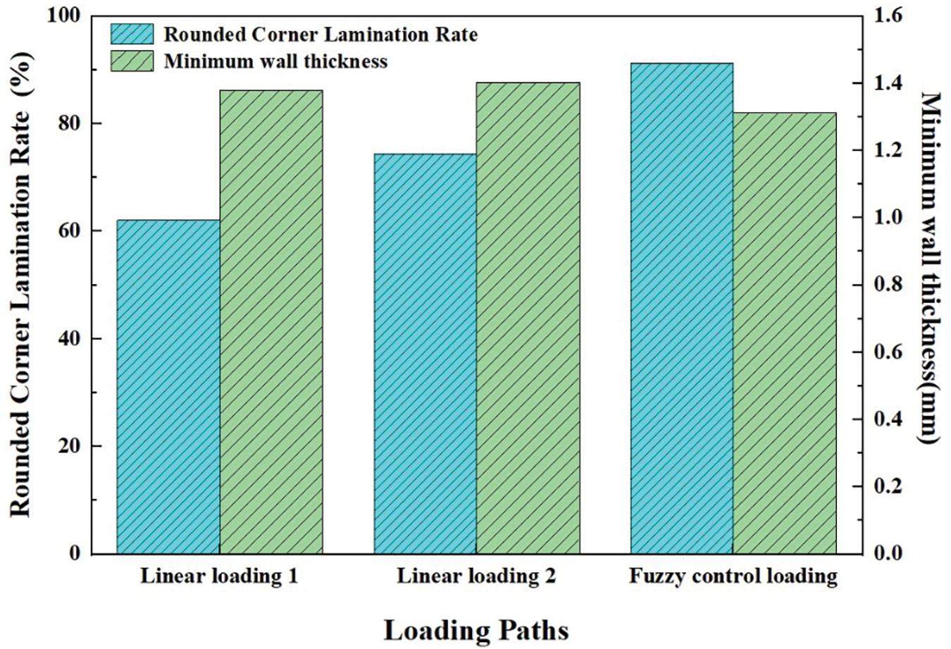
Figure 12: Comparison of forming results of different loading paths

Figure 13: Wall thickness distribution for three loading paths
Compared with linear loading Path 1 and linear loading Path 2, the loading path form fuzzy control optimization algorithm improved the accuracy of the filleting rate of rounded corners. The round corner lamination rate of the tube after fuzzy control optimization is 91.2%, while round corner lamination rate of linear loading Path 1 and Path 2 was 62% and 74.4%, and significantly improved by 47.1% and 22.6%, respectively. This is beneficial for the integration of fuzzy control and finite element analysis, and provides guidance for future experiments.
The ablative study of axial feed was carried out. The wall thickness distribution and fillet expansion rate were analyzed when pressure was 44 MPa without axial feeding shown in Fig. 14. It can be seen from the results that the wall thickness thinning was more serious, and the maximum thinning rate was 19.3%, the lamination rate at the rounded corners was 78%. The forming effect is not as good as that of fuzzy control optimization.
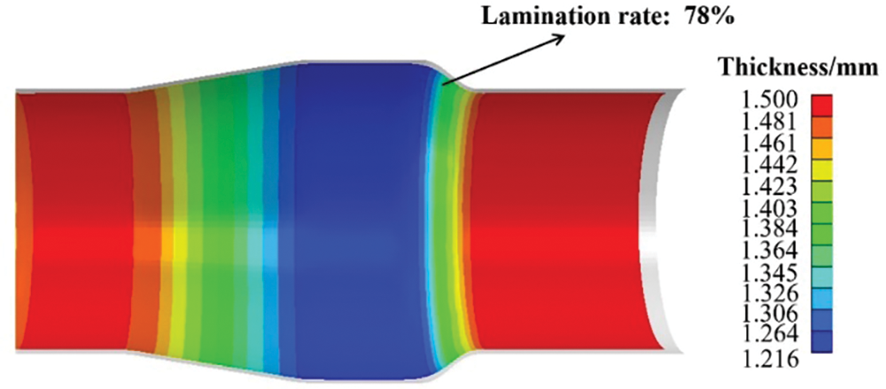
Figure 14: Wall thickness distribution for three loading paths
Analyzing the causes of the above results. During the tube forming stage, as internal pressure increases and the tube undergoes plastic deformation, the straight tube material of the reducer undergoes linear deformation, reaching the yield limit and entering the plastic deformation stage. As the material enters the expansion area and begins to expand. The internal pressure and replenishment process accelerates to meet the deformation requirements. However, the expansion process varies from one structure to another due to the different physical properties of the tubes and the structures of the parts targeted for final expansion. The relationship between the internal pressure and the amount of filler material used must be determined for each structure individually. Because of the left side of the tube centerline of the tube in the forming process due to the axial feeds led to a slight thickening of the wall thickness did not occur in other plastic deformation, the main expansion area occurs in the right side of the tube centerline, so in the pre-forming period to make the tube fittings right push the head to a larger axial feeds to ensure that when the internal pressure gradually increased to avoid the tube fittings to burst and other material defects in the behavior. Therefore, the axial feeds increases faster than the internal pressure in the early stage of modeling; In the late stage of forming, after the rapid increase of axial feeds in the pre-forming stage, wrinkles may appear in the straight tube area, and the wall thickness in the expansion area is too thin, at this time, the continued increasing of internal pressure will lead to the bursting of tube fittings, so it enters the pressure holding and forming stage to enable the tube fittings to achieve a more optimal state of the mold, and the growth of axial feeds and internal pressure is slowed down compared with the pre-forming stage. This proves that the loading paths obtained based on fuzzy control optimization is in accordance with the hydroforming mechanism of the variable diameter tube.
Compared with other optimization algorithms, such as self-feeding and optimization of loading paths by optimization seeking algorithm, fuzzy control method balance optimization accuracy and optimization efficiency. The change curve of tube pressure and natural feeding over time was recorded, and estimates the required minimum feeding amount according to the maximum thinning rate of the previous step in self-feeding method. The advantage of self-feeding method is that it can quickly obtain a more reasonable loading curve, but it is only applicable to the straight axis with simple geometry. In some studies [23], the number of optimization iterations of optimization seeking algorithm ranged from 200–320 in order to obtain better optimization accuracy, in which each iteration in the field of material forming requires the use of finite element analysis, and optimization is time-consuming.
4.3 Verification of Experimental Results
In order to verify the reliability of the simulation results, 5A02 thin-walled aluminum alloy tubes were subjected to variable diameter tube hydroforming experiments. The thickness of the final part of the tube hydroforming under three loading paths was tested and compared with the simulation. As shown in Fig. 15, the errors of both experimental verification and finite element simulation results can be controlled within 5%, which verifies the accuracy of the simulation results. Compared with other optimization methods, the fuzzy control optimized loading path improves the wall thickness uniformity and maximum thinning rate at rounded corners. The minimum wall thickness in the expansion area can be up to 1.32 mm, the maximum thinning rate is 12.4%, and the filming rate at the round corner is 90.4%.
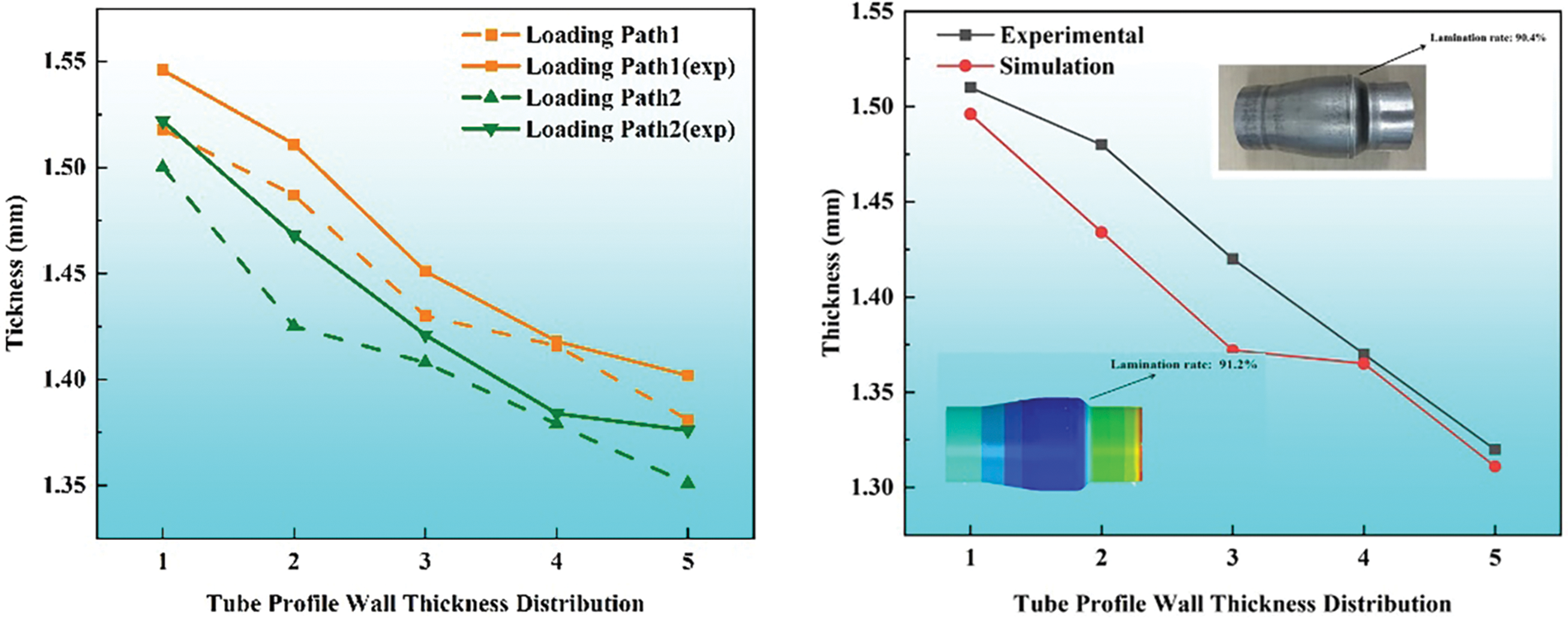
Figure 15: Comparison of experimental and simulation forming effects
The fuzzy control optimization method can provide reference for other types of materials forming through the following process: Firstly, an accurate finite element simulation model is established according to the tube forming process. Secondly, the value range of the parameters to be optimized is determined according to the pre-experiment, and then the fuzzy rule library is established to complete the design of the fuzzy rule controller. Finally, the loading path of materials forming is optimized and experimentally verified.
(1) Fuzzy control optimization of loading path of variable diameter tube hydroforming was carried out. Compared with the two linear loading paths, the optimized loading path improves the wall thickness uniformity and the forming effect greatly. The round corner lamination rate of the tube after fuzzy control optimization is 91.2%, which is significantly increased by 47.1% and 22.6% compared with linear loading Path 1 and Path 2, respectively.
(2) The minimum wall thickness of the reducer test guided by the simulation results of the loading paths obtained based on fuzzy control was 1.32 mm, the maximum thinning rate was 12.4%, and the lamination rate at the rounded corners was 90.4%.
(3) The real-time detection of forming parameters can be developed in the future, and the fuzzy control system can be embedded into the hydroforming machine as embedded software for the hydroforming process. Precise forming stages for differently shaped and more complex structural parts and the development of an adaptive fuzzy control designer by means of intelligent algorithms are possible.
Acknowledgement: The author would like to thank Foshan Yeyi Technology Co., Ltd. for experimental debugging.
Funding Statement: This research was supported by the Shenyang Science and Technology Program (grant number 22-301-1-10).
Author Contributions: Yong Xu: Methodology, Investigation, Funding Acquisition, Conceptualization, Supervision. Xuewei Zhang: Software, Investigation, Validation, Writing. Wenlong Xie: Methodology, Investigation, Conceptualization, Writing—Reviewing & Editing. Shihong Zhang: Conceptualization, Writing—Reviewing & Editing. Xinyue Huang: Methodology, Investigation. Yaqiang Tian: Methodology. Liansheng Chen: Writing—Reviewing & Editing. All authors reviewed the results and approved the final version of the manuscript.
Availability of Data and Materials: The data that support the findings of this study are available on request from the corresponding author, upon reasonable request.
Ethics Approval: The research contents of the article do not violate ethics.
Conflicts of Interest: The authors declare no conflicts of interest to report regarding the present study.
References
1. M. Zhan et al., “A method for establishing the plastic constitutive relationship of the weld bead and heat-affected zone of welded tubes based on the rule of mixtures and a microhardness test,” Mat Sci. Eng. A-Struct., vol. 527, no. 12, pp. 2864–2874, May 2010. doi: 10.1016/j.msea.2010.01.009. [Google Scholar] [CrossRef]
2. L. H. Lang et al., “Hydroforming highlights: Sheet hydroforming and tube hydroforming,” J. Mater. Process. Tech., vol. 151, no. 1–3, pp. 165–177, Sep. 2004. doi: 10.1016/j.jmatprotec.2004.04.032. [Google Scholar] [CrossRef]
3. B. Endelt, “In-process feedback control of tube hydro-forming process,” Int. J. Adv. Manuf. Tech., vol. 119, no. 11, pp. 7723–7733, Jan. 2022. doi: 10.1007/s00170-022-08683-6. [Google Scholar] [CrossRef]
4. R. Pourhamid and A. Shirazi, “A comprehensive damage criterion in tube hydroforming,” Proc. Inst. Mech. Eng. B: J. Eng. Manuf., vol. 235, no. 3, pp. 417–430, Oct. 2021. doi: 10.1177/0954405420962. [Google Scholar] [CrossRef]
5. S. H. Li, B. Yang, W. G. Zhang, and Z. Q. Lin, “Loading path prediction for tube hydroforming process using a fuzzy control strategy,” Mater. Design., vol. 29, no. 6, pp. 1110–1116, Jul. 2007. doi: 10.1016/j.matdes.2007.06.008. [Google Scholar] [CrossRef]
6. F. Dohmann and C. Hartl, “Hydroforming-a method to manufacture light-weight parts,” J. Mater. Process. Tech., vol. 60, no. 1–4, pp. 669–676, Jun. 1996. doi: 10.1016/0924-0136(96)02403-X. [Google Scholar] [CrossRef]
7. Y. Aue-U-Lan, G. Ngaile, and T. Altan, “Optimizing tube hydroforming using process simulation and experimental verification,” J. Mater. Process. Tech., vol. 146, no. 1, pp. 137–143, Feb. 2004. doi: 10.1016/S0924-0136(03)00854-9. [Google Scholar] [CrossRef]
8. J. B. Yang, B. H. Jeon, and S. I. Oh, “Design sensitivity analysis and optimization of the hydroforming process,” J. Mater. Process. Tech., vol. 113, no. 1–3, pp. 666–672, Jun. 2001. doi: 10.1016/S0924-0136(01)00670-7. [Google Scholar] [CrossRef]
9. R. Di Lorenzo, G. Ingarao, F. Gagliardi, and L. Filice, “Experimental validation of optimisation strategies in hydroforming of T-shaped tubes,” Int. J. Mater. Form., vol. 1, no. S1, pp. 323–326, Apr. 2008. doi: 10.1007/s12289-008-0060-x. [Google Scholar] [CrossRef]
10. R. Di Lorenzo, G. Ingarao, and F. Chinesta, “A gradient-based decomposition approach to optimize pressure path and counterpunch action in Y-shaped tube hydroforming operations,” Int. J. Adv. Manuf. Tech., vol. 44, pp. 49–60, Nov. 2008. doi: 10.1007/s00170-008-1813-x. [Google Scholar] [CrossRef]
11. F. Mohammadi and M. Mosavi Mashadi, “Determination of the loading path for tube hydroforming process of a copper joint using a fuzzy controller,” Int. J. Adv. Manuf. Tech., vol. 43, no. 1–2, pp. 1–10, Aug. 2008. doi: 10.1007/s00170-008-1697-9. [Google Scholar] [CrossRef]
12. K. Manabe, M. Suetake, H. Koyama, and M. Yang, “Hydroforming process optimization of aluminum alloy tube using intelligent control technique,” Int. J. Mach. Tool. Manu., vol. 46, no. 11, pp. 1207–1211, Sep. 2006. doi: 10.1016/j.ijmachtools.2006.01.028. [Google Scholar] [CrossRef]
13. Y. Zhang, C. Mohammed, and Z. R. Xiang, “Predefined-time adaptive fuzzy control for a class of nonlinear systems with output hysteresis,” IEEE Trans. Fuzzy. Syst., vol. 31, no. 8, pp. 2522–2531, Dec. 2022. doi: 10.1109/TFUZZ.2022.3228012. [Google Scholar] [CrossRef]
14. D. Cui, C. K. Ahn, and Z. R. Xiang, “Fault-tolerant fuzzy observer-based fixed-time tracking control for nonlinear switched systems,” IEEE Trans. Fuzzy. Syst., vol. 31, no. 12, pp. 4410–4420, Dec. 2023. doi: 10.1109/TFUZZ.2023.3284917. [Google Scholar] [CrossRef]
15. B. G. Teng, K. Li, and S. J. Yuan, “Optimization of loading path in hydroforming T-shape using fuzzy control algorithm,” Int. J. Adv. Manuf. Tech., vol. 69, pp. 1079–1086, Jun. 2013. doi: 10.1007/s00170-013-5086-7. [Google Scholar] [CrossRef]
16. Y. M. Hwang, C. H. Zhang, C. C. Chen, and S. Yoshihara, “Feeding path and movable die design in tube hydroforming of metal bellows,” Int. J. Adv. Manuf. Tech., vol. 129, pp. 2399–2414, Oct. 2023. doi: 10.1007/s00170-023-12492-w. [Google Scholar] [CrossRef]
17. A. A. El-Aty et al., “Finite element analysis and experimental study of manufacturing thin-walled five-branched AISI 304 stainless steel tubes with different diameters using a hydroforming process,” Materials, vol. 17, no. 1, Dec. 2023, Art. no. 104. [Google Scholar]
18. L. Galdos, J. Trinidad, N. Otegi, and C. Garcia, “Friction modelling for tube hydroforming processes—A numerical and experimental study with different viscosity lubricants,” Materials, vol. 15, no. 16, Aug. 2022, Art. no. 5655. doi: 10.3390/ma15165655. [Google Scholar] [PubMed] [CrossRef]
19. G. Ngaile and M. Avila, “Improving material formability and tribological conditions through dual-pressure tube hydroforming,” J. Manuf. Mater. Process., vol. 7, no. 4, Jul. 2023, Art. no. 126. doi: 10.3390/jmmp7040126. [Google Scholar] [CrossRef]
20. Y. M. Hwang and I. P. Hsu, “Die design and finite element analysis of welding seams during aluminum alloy tube extrusion,” Metals, vol. 13, no. 5, May 2023, Art. no. 0911. doi: 10.3390/met13050911. [Google Scholar] [CrossRef]
21. N. D. Phu, N. N. Hung, A. Ahmadian, and N. Senu, “A new fuzzy PID control system based on fuzzy PID controller and fuzzy control process,” Int. J. Fuzzy. Syst., vol. 22, no. 7, pp. 2163–2187, Aug. 2020. doi: 10.1007/s40815-020-00904-y. [Google Scholar] [CrossRef]
22. S. Jirathearanat, C. Hartl, and T. Altan, “Hydroforming of Y-shapes—product and process design using FEA simulation and experiments,” J. Mater. Process. Tech., vol. 146, no. 1, pp. 124–129, Feb. 2004. doi: 10.1016/S0924-0136(03)00852-5. [Google Scholar] [CrossRef]
23. S. M. H. Seyedkashi, H. M. Naeini, and G. H. Liaghat, “The effect of tube dimensions on optimized pressure and force loading paths in tube hydroforming process,” J. Mech. Sci. Technol., vol. 26, pp. 1817–1822, Jun. 2012. doi: 10.1007/s12206-012-0430-7. [Google Scholar] [CrossRef]
Cite This Article
 Copyright © 2024 The Author(s). Published by Tech Science Press.
This work is licensed under a Creative Commons Attribution 4.0 International License , which permits unrestricted use, distribution, and reproduction in any medium, provided the original work is properly cited.


 Submit a Paper
 Propose a Special lssue
 View Full Text
 Download PDF
 Downloads
 Citation Tools