
 Submit a Paper
 Propose a Special lssue
 Open Access
ARTICLE

Path Planning of Multi-Axis Robotic Arm Based on Improved RRT*
1 School of Automation, Guangxi University of Science and Technology, Liuzhou, 545006, China
2 Key Laboratory of AI and Information Processing of Education Department of Guangxi, Hechi University, Hechi, 546300, China
* Corresponding Author: Wenguang Luo. Email:
(This article belongs to the Special Issue: Intelligent Manufacturing, Robotics and Control Engineering)
Computers, Materials & Continua 2024, 81(1), 1009-1027. https://doi.org/10.32604/cmc.2024.055883
Received 09 July 2024; Accepted 02 September 2024; Issue published 15 October 2024
 View Full Text
 Download PDF
Abstract
An improved RRT* algorithm, referred to as the AGP-RRT* algorithm, is proposed to address the problems of poor directionality, long generated paths, and slow convergence speed in multi-axis robotic arm path planning. First, an adaptive biased probabilistic sampling strategy is adopted to dynamically adjust the target deviation threshold and optimize the selection of random sampling points and the direction of generating new nodes in order to reduce the search space and improve the search efficiency. Second, a gravitationally adjustable step size strategy is used to guide the search process and dynamically adjust the step-size to accelerate the search speed of the algorithm. Finally, the planning path is processed by pruning, removing redundant points and path smoothing fitting using cubic B-spline curves to improve the flexibility of the robotic arm. Through the six-axis robotic arm path planning simulation experiments on the MATLAB platform, the results show that the AGP-RRT* algorithm reduces 87.34% in terms of the average running time and 40.39% in terms of the average path cost; Meanwhile, under two sets of complex environments A and B, the average running time of the AGP-RRT* algorithm is shortened by 94.56% vs. 95.37%, and the average path cost is reduced by 55.28% vs. 47.82%, which proves the effectiveness of the AGP-RRT* algorithm in improving the efficiency of multi-axis robotic arm path planning.Keywords
Robotic arms play an important role in many industrial and service sectors, where they are capable of performing a variety of complex tasks such as assembly, welding, and material handling. Robotic arm path planning is a key problem in robotic arm control, which involves finding the optimal path of a robotic arm between a given start and target position for efficient, safe, and precise motion.
Path planning algorithms can be generally categorized into the following four groups: graph-based search algorithms [1,2], artificial potential field methods [3,4], intelligent algorithms [5–7], and sampling-based algorithms [8–11]. Graph-based search algorithms are prone to huge computational burdens in high-dimensional spaces, limiting their applications. Artificial potential field algorithms are often trapped in local optima and have difficulty avoiding interference from obstacles. The convergence speed and stability of intelligent algorithms are affected by parameter settings and initial value selection. Sampling-based algorithms are suitable for path planning in high-dimensional space, which has the characteristics of convenience and efficiency, easy to constrain and probabilistic completeness. Sampling-based algorithms are mainly categorized into probabilistic roadmap (PRM) [12], and rapid search random tree (RRT) [13]. Among them, the RRT algorithm is favored for its fast search speed, powerful exploration ability, and probabilistic completeness. However, its common problems include long generation paths, inefficiency, and the possibility of failing to find feasible paths in complex environments.
To address the shortcomings of RRT algorithms, many scholars have made improvements to RRT algorithms. Adaptive RRT-Connect (ARRT-Connect) [14] effectively solves the narrow-channel planning problem by combining the advantages of the faster bidirectional RRT (RRT-Connect) and rapidly-exploring random vines (RRV). An elastic band-based rapidly-exploring random tree (EB-RRT) [15] realizes real-time optimal motion planning for mobile service robots in dynamic environments by introducing a hierarchical planning framework and dynamic optimization strategies. Rapid exploration of random tree stars (RRT*) [16] effectively improves the quality and efficiency of path planning by separating the expansion and optimization processes using a dual-tree structure while combining the original RRT and modified RRT* strategies. The RRT-Connect algorithm combined with region partitioning (RRT-Connect-RP) [17] realizes the generation of welding paths for arc welding robots in ship subassembly welding by zone partitioning technique, which improves the efficiency of the robotic system and realizes intelligent production. Adaptive Stepsize RRT [18,19] improves the efficiency and accuracy of path planning through an adaptive stepsize strategy. A stream-based VF-RRT* (SVF-RRT*) [20] effectively solves the problem of safe and energy efficient path planning for unmanned surface vehicles (USVs) in large-scale ocean environments with spatially variable currents by means of heuristic intervals, biased sampling, and tree pruning techniques. Gaussian mixture regression-rapid exploration of random tree stars (GMR-RRT*) [21] achieves fast and efficient path planning for mobile robots in different environments by combining Gaussian mixed regression learning and the path planning capability of fast exploring random trees. Bidirectional assisting metric-rapid exploration of random tree stars (Bi-AM-RRT*) [22] significantly improves the motion planning efficiency and path planning efficiency of mobile robots in dynamic environments. Reinforcement learning-rapid search random tree (RL-RRT) [23] provides an effective long-term planning solution for sampling-based motion planning for kinematic dynamics by combining a deep reinforcement learning strategy and a reachability estimator. Rapidly-exploring random trees based on heuristic probability bias-goal (PBG-RRT) [24] improves search efficiency and obstacle avoidance for robotic path planning in 3D space by combining heuristic probability and bias objective factors. Neural RRT* [25] effectively solves the problems of initial solution sensitivity and slow convergence of traditional RRT and its variants by using a non-uniform sampling distribution predicted by the convolutional neural network (CNN) model to guide the sampling process. A reliable and robust rapidly-exploring random tree (R2-RRT*) [26] enhances the fast exploratory randomized tree algorithm for off-road automated ground vehicle task planning in uncertain terrain environments by introducing state and task mobility reliability metrics. vehicle task planning robustness and reliability.
This article explores further improvements to the existing RRT* algorithm. First, the adaptive bias probability sampling strategy is introduced to optimize the selection of random sampling points and dynamically adjust the target deviation threshold according to the environment, so as to accelerate the convergence speed of the algorithm and reduce the generation of redundant nodes. Secondly, the gravitationally adjustable step size strategy is adopted to dynamically adjust the step size according to the target gravitational force and obstacle information in order to improve the search efficiency and enhance the adaptability to different environments. Finally, based on the node reconnection strategy, collision detection is performed after reconnecting the initial path nodes to remove redundant nodes, and three times B-spline curve is performed for path smoothing to optimize the obstacle avoidance path.
2 Robotic Arm Modeling and Collision Detection
2.1 Kinematic Modeling of a Multi-Axis Robotic Arm
The D-H (Denavit-Hartenberg) parametric method [27], which analyzes the motion of a robotic arm in space by establishing kinematic equations, is a commonly used approach for kinematic modeling. It is divided into two forms, Standard DH method (SDH) and Modified DH method (MDH). The MDH method assumes that the axes of all rotating joints are aligned with the Z-axis to simplify the calculation of the kinematic equations. Therefore, the MDH method is chosen to build the D-H parametric model of the robot.
Set
where
After determining the connection coordinate system and the corresponding connection parameters, the forward kinematics equations of the manipulator can be calculated as follows:
where S is the number of arm axes,
In the field of collision detection, there are several commonly used methods, including axis-aligned bounding box (AABB), oriented bounding box (OBB), cylinder enveloping box, and sphere enveloping box. For the robotic arm linkage, the model simplification using a cylindrical bounding box is an effective method because its shape is similar to that of a cylinder. The sphere-surrounding box is especially popular in application scenarios requiring fast response due to the simplicity of its computational process. The mathematical expression of the sphere-surrounding box can be simplified to the problem of calculating the center coordinates of the sphere and the radius of the sphere, as shown in Eq. (3):
where the center coordinate of the enclosing sphere is
Take the cylinder enclosing the box approach to envelope the robotic arm linkage and the sphere enclosing the box approach to envelope the obstacle, the model is simplified as shown in Fig. 1. When computing collision detection, simplifying linkages into line segments and adding the radius of the cylindrical bounding box to that of the spherical bounding box transforms the robot-obstacle collision detection into a segment-sphere intersection problem. This reduces computational overhead, thereby enhancing solving efficiency.
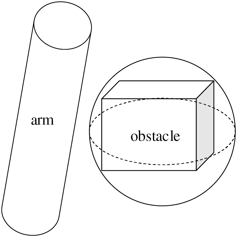
Figure 1: Simplified collision detection model
The main concept of the RRT algorithm is to randomly grow a tree from the initial point until it reaches the target point, as illustrated in Fig. 2. According to the randomly generated sampling state point
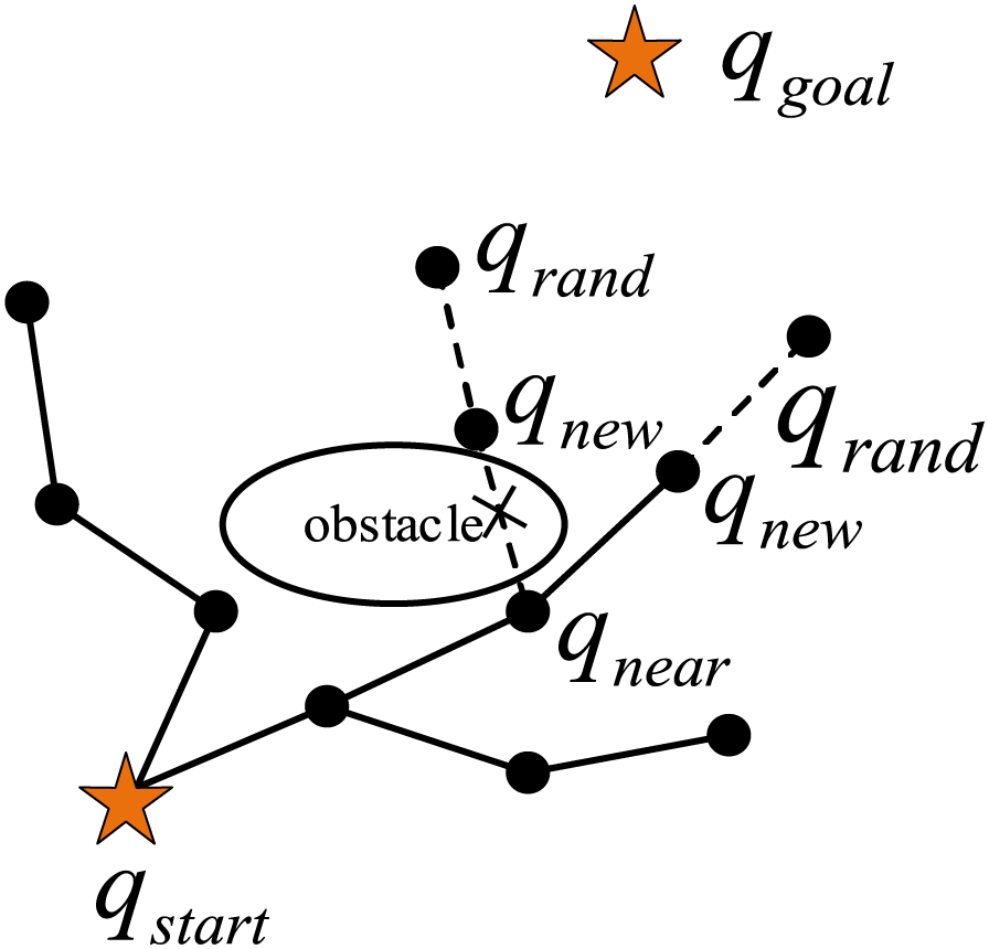
Figure 2: RRT expansion method
The RRT* algorithm improves the performance of the RRT algorithm by introducing a reselection and reconnection mechanism for the parent nodes, and Fig. 3 demonstrates the effect of this improvement. It is important to note that the RRT* algorithm enhances performance by optimizing the configuration space (the joint space of the robotic arm) instead of the task space (such as Cartesian space). The RRT* algorithm updates the parent node by reducing the path cost to the starting point and, after this adjustment, it replans the paths for all adjacent nodes. This algorithm increases the probability of obtaining an optimal or near-optimal path in the configuration space. Thus, the effect in Fig. 3 reflects the impact of mapping obstacles in the configuration space on path planning.
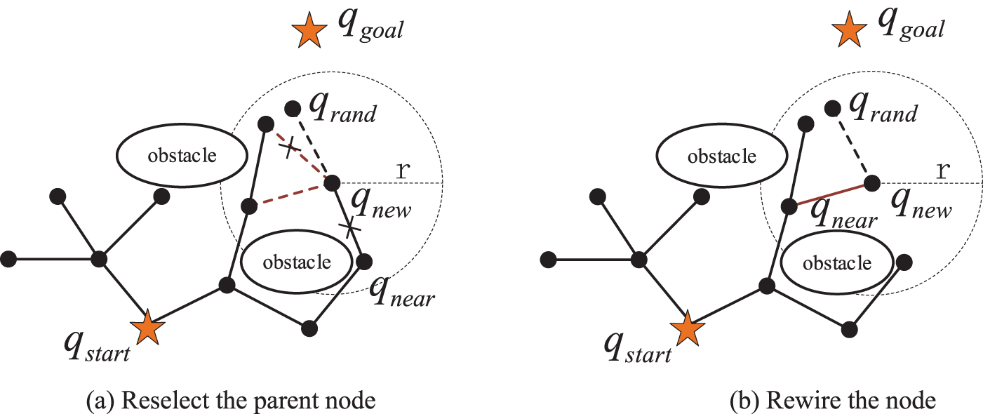
Figure 3: RRT* expansion method
4 Improvement of the RRT* Algorithm
4.1 Adaptive Biased Probabilistic Sampling Strategy
The RRT* algorithm inherits the similar sampling method of RRT, but suffers from a lack of goal-orientation, leading to the generation of redundant nodes, which in turn reduces the overall sampling efficiency. To tackle this problem, a target bias strategy is introduced, directing the sampling toward the target to minimize the creation of unnecessary nodes and enhance the efficiency of path planning. The idea of this strategy is shown in Eq. (4). In this equation, a random distribution of the target bias is used, which is not uniformly random but enhances the probability of sampling near the target by directing the random samples towards the target region.
where
When
Specifically, the initial value of
where k is an empirical coefficient (usually between 0.1 and 0.5), d is the distance between the starting point and the target point, and n is the magnification factor.
where
Fig. 4 shows a 2D simulation comparison between the RRT* algorithm and the RRT* algorithm that incorporates an adaptive biased probabilistic sampling strategy, referred to as the A-RRT* (Adaptive RRT*) algorithm, which can be seen to generate fewer nodes than the RRT* algorithm.
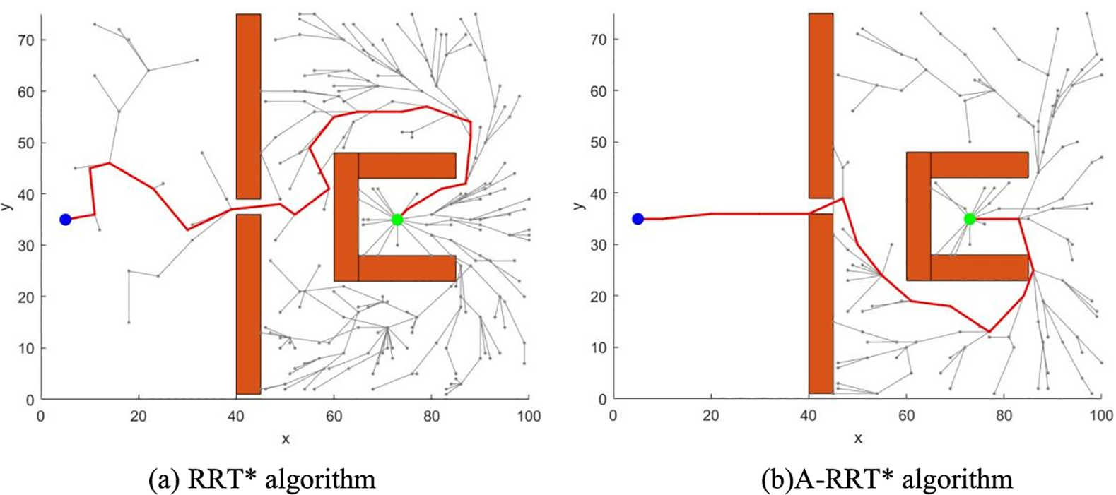
Figure 4: Comparison of RRT* algorithm before and after improvement
4.2 Gravitationally Adjustable Step Size Strategy
In the RRT* algorithm, the step size is a key factor that directly affects the efficiency of the pathfinding process. When the environment is free of obstacles, increasing the step size reduces the search time. However, in the presence of obstacles, too large a step size is prone to cause the algorithm to fall into a narrow region, leading to difficulties in finding the target point and feasible paths; while too small a step size produces redundant nodes and reduces the search efficiency. Therefore, the gravitationally adjustable step-size strategy takes the gravitational coefficient and obstacles into account to achieve dynamic adjustment of the step-size, which can optimize the performance of the algorithm, and its specific principles are as follows:
The new node formula for the RRT* algorithm is:
where
When the idea of target gravity is added, its new nodal formula is:
where
Order:
where
The expression for the gravitational coefficient is:
where
The initial step size is preset to be
where
The selection of
From Eq. (12), when node
4.3 Path Optimization Strategy
The RRT* algorithm, when applied to 3D space for path exploration, yields a continuous line formed by a chain of discrete points. However, this path may be curved and unsmooth and contain many redundant nodes, which makes it difficult for the robotic arm to operate smoothly and thus reduces the service life of the robotic arm. Therefore, path optimization is needed, which is divided into the removal of redundant nodes and smoothing.
The basic principle of redundant node removal is that the nodes on the path are labeled in traversal order as a1, a2,..., an, where a1 is the target node and an is the start node. Starting from a1, it tries to establish a connection with a2, a3,...., an to establish a connection. During the connection attempt, collision detection is performed for each connection. If a collision occurs while trying to connect a1 with the gth node (1 < g ≤ n), a1 establishes a connection directly with the g-1th node and ignores the gth node. The g-1th node is used as the new connection point, and collision detection and redundant node removal continue for subsequent nodes. After each redundant node removal, the path is updated and the connection verified by collision detection is retained. The algorithm ends when all nodes are collision detected and no collision occurs, or when the starting node is reached. The final optimized path obtained has less number of nodes while satisfying collision detection. As shown in Fig. 5a, the black path is the initial path, the red dashed line is the connection attempted to be established, and the green path in Fig. 5b is the path after removing the redundant nodes (a2, a3, a6), i.e., path a8-a7-a5-a4-a1.
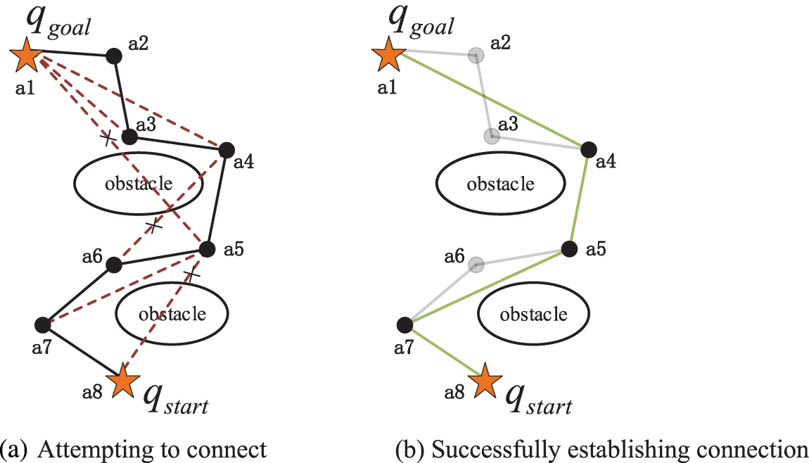
Figure 5: Schematic diagram of redundant point removal
After removing the redundant nodes, the path is shorter and has fewer turning points, but the path is zigzag, as shown in Fig. 5b, which is more zigzag and will lead to a serious jerky phenomenon of the robotic arm during operation. To solve this problem, the introduction of cubic uniform B-spline curves for path smoothing can effectively smooth the zigzag paths and improve the continuity and maneuverability of the paths. k-order B-spline function expression is:
where
where k denotes the number of curves and the subscript i denotes the ordinal number.
The basis function of the cubic B-spline curve to optimize the smoothness of the path is given by:
Then the 3 times B-spline segments are:
However, the smoothing process is not without risk. The original path has been configured spatially mapped in joint space to ensure that the path does not collide with obstacles. However, the smoothed path may collide with the robotic arm due to the curve adjustment. Therefore, after applying B-splines to smooth the path, collision detection must be re-performed to ensure the safety and feasibility of the final path. Finally, a curved line segment was successfully smoothed on the MATLAB platform, as shown in Fig. 6.
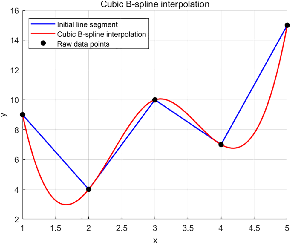
Figure 6: Curve smoothing processing map
In summary, an improved RRT* algorithm is proposed by fusing the adaptive biased probabilistic sampling strategy, the gravitationally adjustable step-size strategy, and the path optimization strategy, referred to as the AGP-RRT* algorithm.
5 Simulation Experiment and Result Analysis
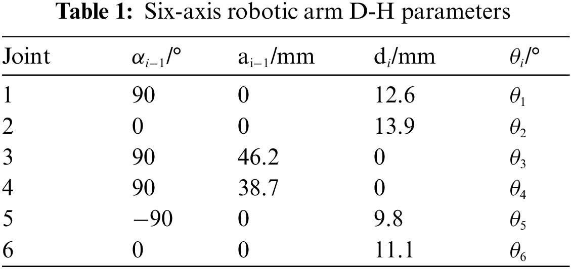
To confirm the efficacy, dependability, and superiority of the proposed AGP-RRT* for multi-axis robotic arm path planning, the algorithm’s performance is tested within a three-dimensional setting. The six-axis robotic arm was selected as the research object and simulation experiments were carried out based on its D-H parameters (see Table 1). Table 1 shows one of the customized robot parameters, where
5.1 Three-Dimensional Simulation
The task of 3D simulation is to ensure that the algorithm can find a path from the starting point to the target point, and at the same time realize the avoidance of obstacles in the path planning process. The experiment sets up a simulation environment of 100 × 100 × 85 size, and sets 9 spherical obstacles of different sizes in blue color. The start point is set as [5, 5, 5], the end point is set as [80, 70, 80], the step size of the algorithm is 5, and the target bias probability is 0.7. Considering that the algorithm has a certain stochastic nature, the experiments are conducted 50 times to guarantee the dependability of the outcomes. The results and key data of the experiments are shown in Fig. 7 and Table 2, respectively.
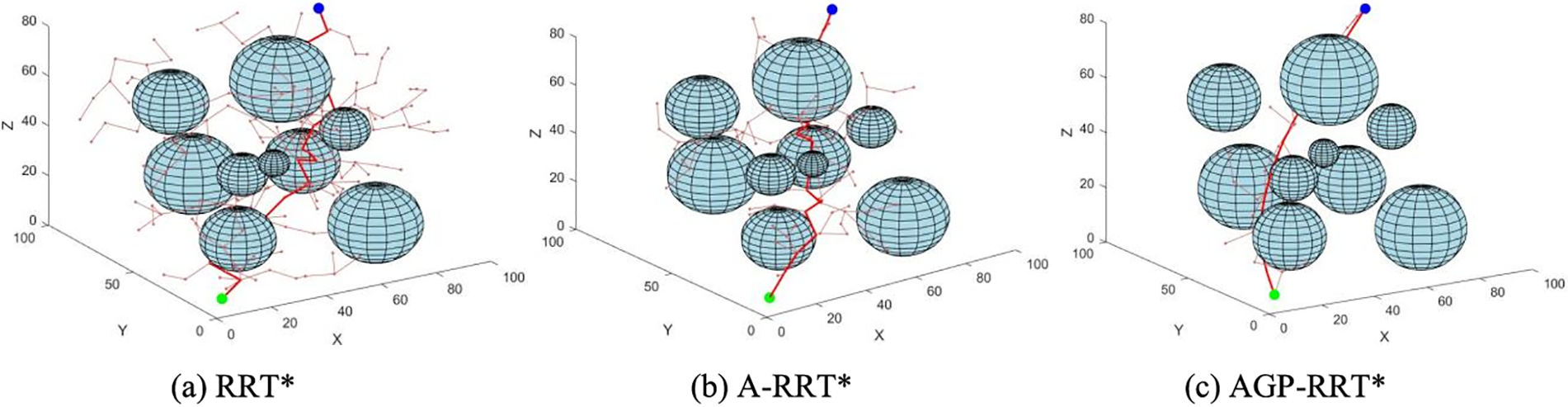
Figure 7: Simulation of 3D path planning for each algorithm
As shown in Fig. 7, the red lines indicate the final path of the algorithm, and the pink lines indicate the branches of the expanded tree. According to the data analysis in Table 2, it can be seen that the AGP-RRT* algorithm achieves 88.524% reduction in search time and 30.22% reduction in average path length compared to the RRT* algorithm; compared to the A-RRT* algorithm, the AGP-RRT* algorithm reduces the path cost by 16.326% and reduces the search time by 72.47%. The experimental results illustrate that the AGP-RRT* algorithm provides superior path planning performance in 3D environments.
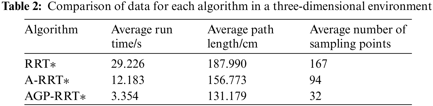
5.2 Six-Axis Robotic Arm Obstacle Avoidance Path Planning Simulation
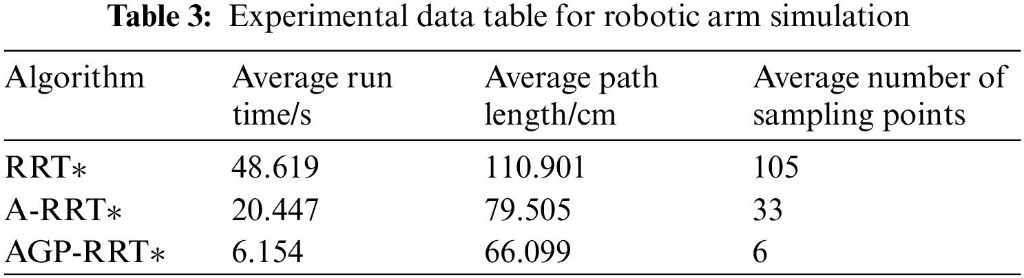
The six-axis robotic arm simulation experiment is performed on MATLAB software as shown in Fig. 8. There are four obstacles in the experimental environment, including two blue rectangular obstacles and two blue spherical obstacles. The start point is set as (−65, −25, 70) and the target point is set as (50, −30, −35). The robot arm is required to chart a course that bypasses any obstacles, extending from the origin to the endpoint.
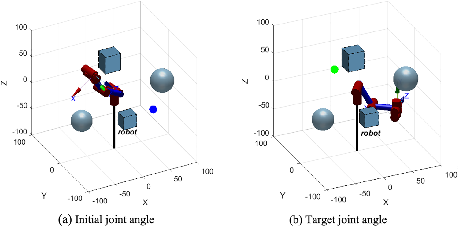
Figure 8: Simulation environment of robotic arm
Kinematic constraints are incorporated into the experiments to ensure that the movement of the robotic arm conforms to its physical characteristics and operational capabilities. The kinematic constraints are:
Positional constraints:
Speed constraints:
Acceleration constraints:
where j represents the jth joint,
The experiment is configured with a maximum of 10,000 iterations. The running results are shown in Figs. 9 and 10, where the red line represents the final route, the blue line denotes the initial, unrefined path, and the orange illustrates the algorithm’s search progression. In Fig. 9a, the RRT* algorithm, due to its lack of goal orientation, results in a large sampling space and long and winding generated paths. In contrast, Fig. 9b illustrates the A-RRT* algorithm, which enhances target orientation by introducing adaptive biased probability sampling strategies and adjusting target deviation thresholds based on obstacle information. This approach generates shorter, less winding paths, but its sampling efficiency and path smoothness require improvement. The AGP-RRT* algorithm shown in Fig. 9c further improves the sampling speed by gravitationally dynamically adjusting the step size and generating smooth paths through path optimization processing. Further, it is observed that the joint position trajectory graph of the AGP-RRT* algorithm is smoother than the other two algorithms for robotic arm joint operation as shown in Fig. 10. The results show that the AGP-RRT* algorithm has the fastest search process and generates the best path performance.
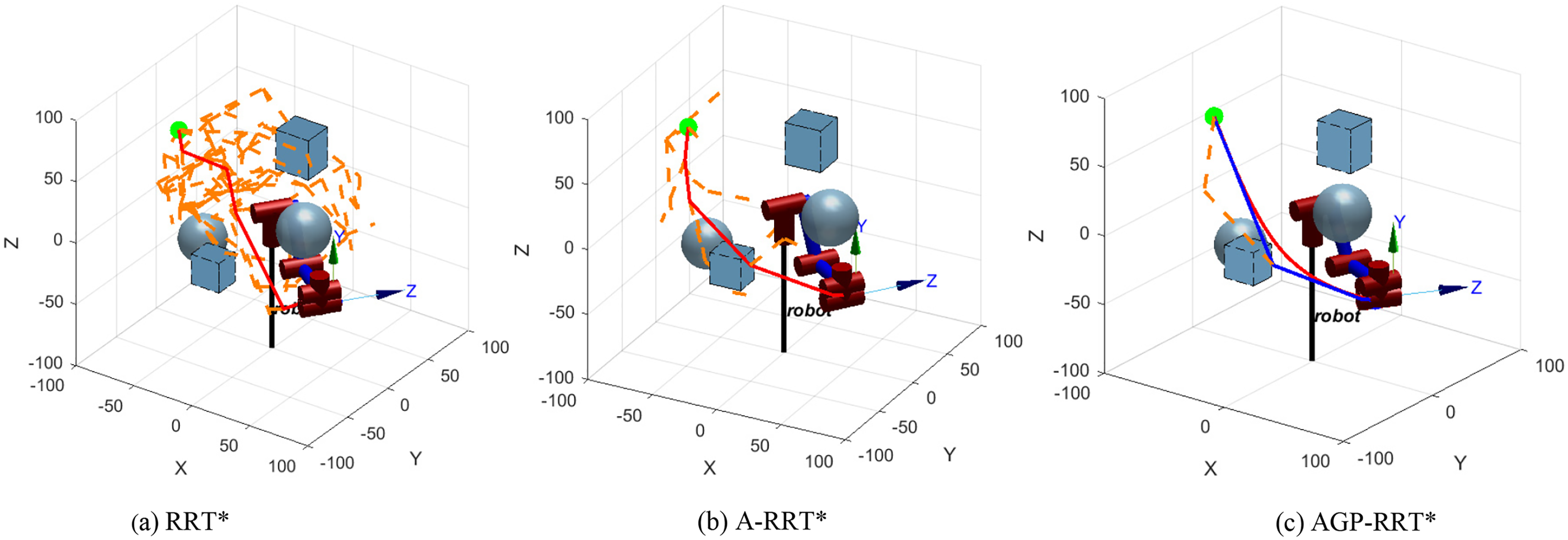
Figure 9: Simulation results of robotic arm path
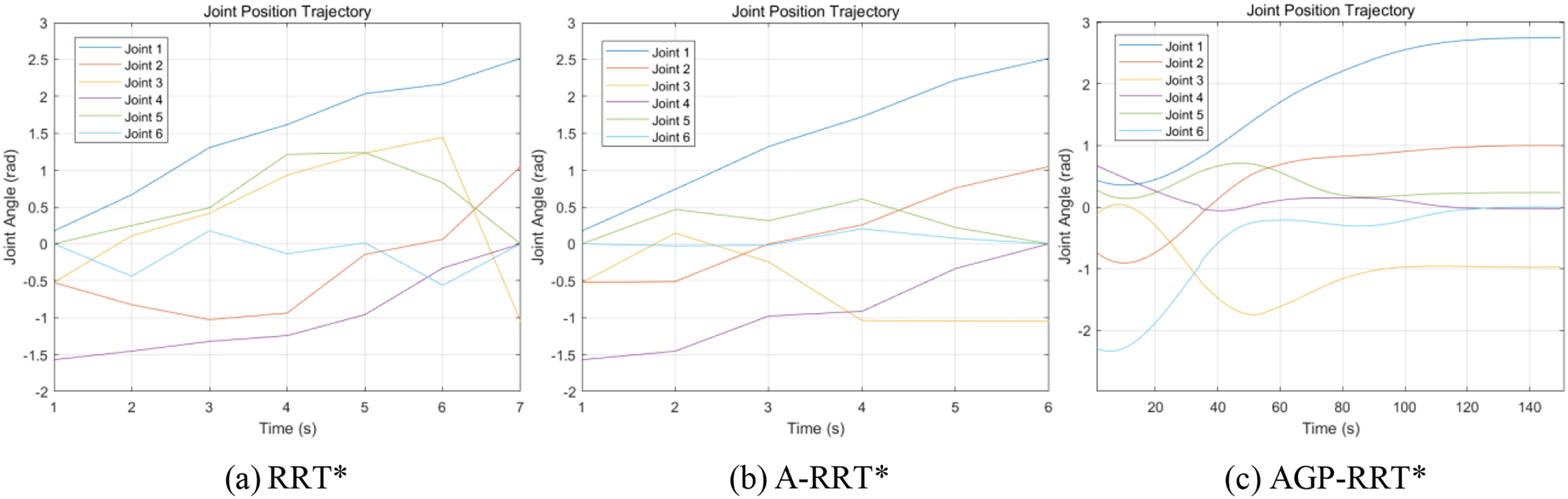
Figure 10: Joint position trajectory
According to the data in Table 3, the AGP-RRT* algorithm shows significant advantages in several indicators. Compared with the RRT* algorithm, the AGP-RRT* algorithm significantly reduces the average running time by 87.34%, and also reduces the average path cost by 40.39%; compared with the A-RRT* algorithm, the AGP-RRT* algorithm further optimizes the algorithmic performance by means of the gravitationally adjustable step-size strategy and the path optimization strategy. Specifically, the AGP-RRT* algorithm reduces 69.90% on the average running time and 16.86% on the average path cost. These results show that the AGP-RRT* algorithm not only improves the convergence speed, but also shortens the length of the generated path.
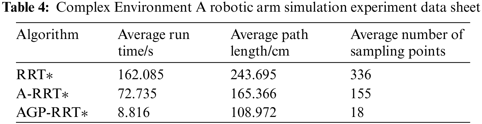
To ensure the adaptability of the proposed AGP-RRT* algorithm within various settings, it has been implemented in two distinct, more intricate scenarios, labeled Environment A and Environment B, each containing a total of eight obstacles. Due to the increase of obstacles, the paths generated by the RRT* and A-RRT* algorithms are more tortuous, especially the RRT* algorithm has more redundant nodes, which are difficult to run directly by the robotic arm, leading to the failure of the algorithm planning, and in order to carry out the comparison between the three, the paths are simplified by its two algorithms in order to ensure the smoothness of the paths. The simulation results are shown in Figs. 11–14.
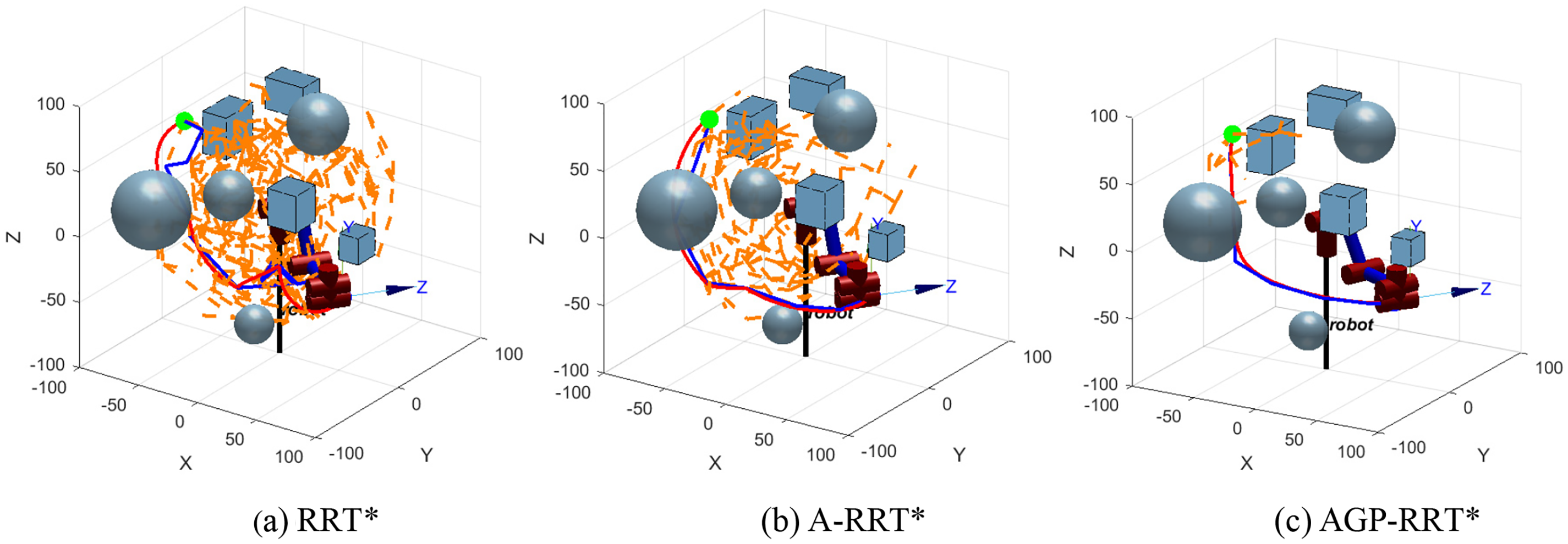
Figure 11: Complex Environment A robotic arm path simulation results
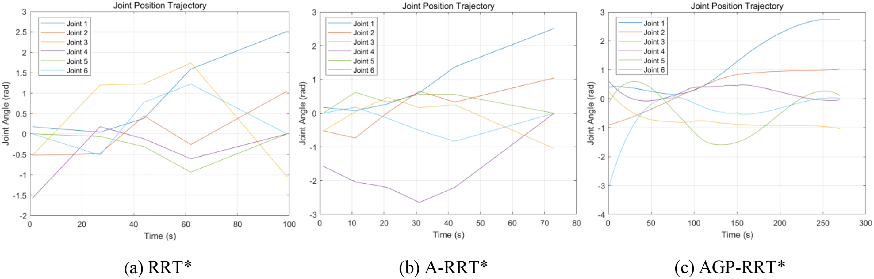
Figure 12: Complex Environment A-joint position trajectory map
Figure 13: B.robotic arm path simulation results
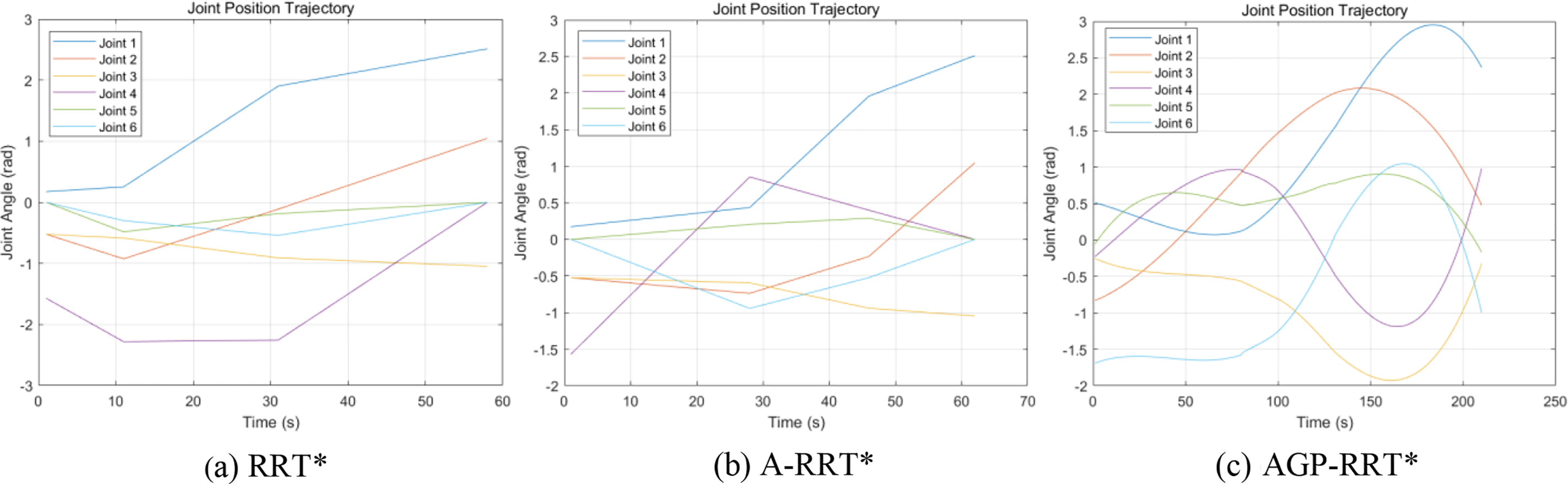
Figure 14: B.joint position trajectory map
From Figs. 11 and 13, it can be seen that the traditional RRT* algorithm is difficult to adapt effectively, and the A-RRT* algorithm performs at a significant discount relative to simple environments. In contrast, the AGP-RRT* algorithm still shows good performance in complex environments. As shown in Figs. 12 and 14, the AGP-RRT* algorithm still outperforms the RRT* and A-RRT* algorithms for its joint position trajectories. Further analyzing the data in Tables 4 and 5, the AGP-RRT* algorithm reduces the average running time by 94.56% and 95.37%, and the average path cost by 55.28% and 47.82% compared to the RRT* algorithm; compared to the A-RRT* algorithm, the average running time is reduced by 87.88% and 89.24%, and the average path cost is reduced by 34.10% and 20.97%, respectively. Also, the AGP-RRT* algorithm generates the least number of nodes.

The above results show that the AGP-RRT* algorithm exhibits significant advantages in several aspects. First, in terms of convergence speed, the significant reduction of the AGP-RRT* algorithm in the average running time (94.56% vs. 95.37% compared to the RRT* algorithm, and 87.88% vs. 89.24% compared to the A-RRT* algorithm) suggests that it is able to find the feasible paths faster. Second, in terms of adaptability, the AGP-RRT* algorithm performs particularly well in complex environments. Even if multiple obstacles are set up in the environment, the AGP-RRT* algorithm is still able to generate smoother paths, whereas traditional RRT* algorithms show obvious path zigzags and redundant nodes when faced with the same complex environments, making it difficult to be directly applied to robotic arm operation.
Finally, in terms of performance advantages, the AGP-RRT* algorithm shows a reduction in the average path cost (55.28% vs. 47.82% compared to the RRT* algorithm, and 34.10% vs. 20.97% compared to the A-RRT* algorithm), which means that the paths it generates are not only shorter, but also likely to lead to higher efficiency and economy in practical applications.
In summary, the AGP-RRT* algorithm demonstrates good performance advantages by significantly improving the convergence speed, enhancing the adaptability, and optimizing the path cost, especially the potential for application in complex environments.
In the simulation verification part, since the six-axis robotic arm is widely used in the industrial field, thus the six-axis robotic arm is selected as the experimental object to fully test the effectiveness and performance of the AGP-RRT* algorithm in path planning. Although the experiment is only a simulation test for the six-axis robotic arm, the AGP-RRT* algorithm has strong generality and adaptability, and can be effectively applied to other types of multi-axis robotic arms in theory. The design idea of the algorithm is compatible with the kinematic model and local constraints of the multi-axis robotic arm, which lays the foundation for its applicability under various motion laws. The adaptive biased probabilistic sampling strategy and the adjustable step size strategy enable the algorithm to flexibly cope with the demands of robotic arms with different numbers of axes.
Furthermore, the AGP-RRT* algorithm can handle various obstacle distributions and path planning complexities by combining environmental adaptation and path smoothing requirements on top of path search and node generation. Therefore, although the experiments only focus on a six-axis robotic arm, in theory, other types of multi-axis robotic arms with limited 3D space and complex joint constraints can also benefit from the algorithm.
In summary, the AGP-RRT* algorithm shows good applicability and potential application value for different types of multi-axis robotic arms in complex environments by virtue of its efficient path planning capability, good adaptability, and optimized path generation.
An AGP-RRT* algorithm is proposed, which aims to optimize the problems of large sampling area, long search time, tortuous paths, and too many redundant points in the traditional RRT* algorithm. The key improvement points of the algorithm include:
(1) Optimizing the sampling of the algorithm by dynamically adjusting the target deviation threshold m, which effectively avoids collisions and reduces the generation of redundant nodes, resulting in better performance of the generated paths.
(2) Dynamically adjusting the step size, combined with the gravitational guidance and obstacle distribution, to further improve the search efficiency of the algorithm.
(3) To improve path smoothness, redundant nodes are removed from the path and the path is optimized using third-order B-splines, enhancing path smoothness.
Through algorithmic 3D environment simulations and simulated experiments with six-axis robotic arms in varying levels of complexity, the AGP-RRT* algorithm has demonstrated significant reductions in path planning time and the generation of superior paths. Due to the generality and applicability of the algorithm, the algorithm can provide some reference value for the path planning of multi-axis robotic arms.
Acknowledgement: This paper grateful thanks to all reviewers for their selfless contributions to science, and to all editors for their outstanding work in improving the quality of the paper.
Funding Statement: The work is supported by Foundation of key Laboratory of AI and Information Processing of Education Department of Guangxi (No. 2022GXZDSY002) (Hechi University), Foundation of Guangxi Key Laboratory of Automobile Components and Vehicle Technology (Nos. 2022GKLACVTKF04, 2023GKLACVTZZ06).
Author Contributions: Study conception and design: Juanling Liang, Wenguang Luo; data collection: Juanling Liang; analysis and interpretation of results: Juanling Liang, Wenguang Luo, Yongxin Qin; draft manuscript preparation: Juanling Liang, Wenguang Luo. All authors reviewed the results and approved the final version of the manuscript.
Availability of Data and Materials: The authors confirm that the data supporting the findings of this study are available within the paper.
Ethics Approval: Not applicable.
Conflicts of Interest: The authors declare that they have no conflicts of interest to report regarding the present study.
References
1. H. Xing, Y. Zhao, Y. Zhang, and Y. Chen, “3D trajectory planning of positioning error correction based on PSO-A* algorithm,” Comput. Mater. Contin., vol. 65, no. 3, pp. 2295–2308, 2020. doi: 10.32604/cmc.2020.011858. [Google Scholar] [CrossRef]
2. C. Lin, Y. He, X. Fang, and C. Wang, “An intelligent vehicle trajectory planning method for parking scenarios,” (in Chinese), J. Shanghai Jiao Tong Univ., vol. 57, no. 3, pp. 345–353, 2023. [Google Scholar]
3. Y. Huang et al., “A motion planning and tracking framework for autonomous vehicles based on artificial potential field elaborated resistance network approach,” IEEE Trans. Ind. Electron., vol. 67, no. 2, pp. 1376–1386, Feb. 2020. doi: 10.1109/TIE.2019.2898599. [Google Scholar] [CrossRef]
4. Z. Pan, C. Zhang, Y. Xia, H. Xiong, and X. Shao, “An improved artificial potential field method for path planning and formation control of the multi-UAV systems,” IEEE Trans. Circuits Syst. II, Exp. Briefs., vol. 69, no. 3, pp. 1129–1133, Mar. 2022. doi: 10.1109/TCSII.2021.3112787. [Google Scholar] [CrossRef]
5. M. Zhang, H. Ren, and Y. Zhou, “Research on global ship path planning method based on improved ant colony algorithm,” IEEE Open J. Intell. Transp. Syst., vol. 4, pp. 143–152, 2023. doi: 10.1109/OJITS.2023.3247377. [Google Scholar] [CrossRef]
6. Z. Lin, K. Wu, R. Shen, X. Yu, and S. Huang, “An efficient and accurate A-star algorithm for autonomous vehicle path planning,” IEEE Trans. Veh. Technol., vol. 73, no. 6, pp. 9003–9008, Jun. 2024. doi: 10.1109/TVT.2023.3348140. [Google Scholar] [CrossRef]
7. D. González, J. Pérez, V. Milanés, and F. Nashashibi, “A review of motion planning techniques for automated vehicles,” IEEE Trans. Intell. Transp. Syst., vol. 17, no. 4, pp. 1135–1145, Apr. 2016. doi: 10.1109/TITS.2015.2498841. [Google Scholar] [CrossRef]
8. Y. Zhang, Z. Ju, H. Zhang, and Z. Qi, “3-D path planning using improved RRT* algorithm for robot-assisted flexible needle insertion in multilayer tissues,” IEEE Can. J. Electr. Comput. Eng., vol. 45, no. 1, pp. 50–62, 2022. doi: 10.1109/ICJECE.2021.3120324. [Google Scholar] [CrossRef]
9. C. -B. Moon and W. Chung, “Kinodynamic planner dual-tree RRT (DT-RRT) for two-wheeled mobile robots using the rapidly exploring random tree,” IEEE Trans. Ind. Electron., vol. 62, no. 2, pp. 1080–1090, Feb. 2015. doi: 10.1109/TIE.2014.2345351. [Google Scholar] [CrossRef]
10. J. Dai, Y. Zhang, and H. Deng, “Novel potential guided bidirectional RRT* with direct connection strategy for path planning of redundant robot manipulators in joint space,” IEEE Trans. Ind. Electron., vol. 71, no. 3, pp. 2737–2747, Mar. 2024. doi: 10.1109/TIE.2023.3269462. [Google Scholar] [CrossRef]
11. J. Qi, H. Yang, and H. Sun, “MOD-RRT*: A sampling-based algorithm for robot path planning in dynamic environment,” IEEE Trans. Ind. Electron., vol. 68, no. 8, pp. 7244–7251, Aug. 2021. doi: 10.1109/TIE.2020.2998740. [Google Scholar] [CrossRef]
12. M. F. Ozkan, L. R. G. Carrillo, and S. A. King, “Rescue boat path planning in flooded Urban environments,” in Proc. IEEE Int. Symp. Meas. Control Robot. (ISMCR), Houston, TX, USA, 2019, pp. B2-2-1–B2-2-9. [Google Scholar]
13. H. -T. L. Chiang and L. Tapia, “COLREG-RRT: An RRT-based COLREGS-compliant motion planner for surface vehicle navigation,” IEEE Robot. Autom. Lett., vol. 3, no. 3, pp. 2024–2031, Jul. 2018. doi: 10.1109/LRA.2018.2801881. [Google Scholar] [CrossRef]
14. B. Li and B. Chen, “An adaptive rapidly-exploring random tree,” IEEE/CAA J. Autom. Sinica., vol. 9, no. 2, pp. 283–294, Feb. 2022. doi: 10.1109/JAS.2021.1004252. [Google Scholar] [CrossRef]
15. J. Wang, M. Q. H. Meng, and O. Khatib, “EB-RRT: Optimal motion planning for mobile robots,” IEEE Trans. Autom. Sci. Eng., vol. 17, no. 4, pp. 2063–2073, Oct. 2020. doi: 10.1109/TASE.2020.2987397. [Google Scholar] [CrossRef]
16. L. Chen, Y. Shan, W. Tian, B. Li, and D. Cao, “A fast and efficient double-tree RRT∗-like sampling-based planner applying on mobile robotic systems,” IEEE/ASME Trans. Mechatron., vol. 23, no. 6, pp. 2568–2578, Dec. 2018. doi: 10.1109/TMECH.2018.2821767. [Google Scholar] [CrossRef]
17. X. Wang, Y. Hua, J. Gao, Z. Lin, and R. Yu, “Digital twin implementation of autonomous planning arc welding robot system,” Complex Syst. Model. Simul., vol. 3, no. 3, pp. 236–251, Sep. 2023. doi: 10.23919/CSMS.2023.0013. [Google Scholar] [CrossRef]
18. B. An, J. Kim, and F. C. Park, “An adaptive stepsize RRT planning algorithm for open-chain robots,” IEEE Robot. Autom. Lett., vol. 3, no. 1, pp. 312–319, Jan. 2018. doi: 10.1109/LRA.2017.2745542. [Google Scholar] [CrossRef]
19. H. Shen, W. -F. Xie, J. Tang, and T. Zhou, “Adaptive manipulability-based path planning strategy for industrial robot manipulators,” IEEE/ASME Trans. Mechatron., vol. 28, no. 3, pp. 1742–1753, Jun. 2023. doi: 10.1109/TMECH.2022.3231467. [Google Scholar] [CrossRef]
20. W. Zhang, L. Shan, L. Chang, and Y. Dai, “SVF-RRT*: A stream-based VF-RRT* for USVs path planning considering ocean currents,” IEEE Robot. Autom. Lett., vol. 8, no. 4, pp. 2413–2420, Apr. 2023. doi: 10.1109/LRA.2023.3245409. [Google Scholar] [CrossRef]
21. J. Wang, T. Li, B. Li, and M. Q. -H. Meng, “GMR-RRT*: Sampling-based path planning using Gaussian mixture regression,” IEEE Trans. Intell. Veh., vol. 7, no. 3, pp. 690–700, Sep. 2022. doi: 10.1109/TIV.2022.3150748. [Google Scholar] [CrossRef]
22. Y. Zhang, H. Wang, M. Yin, J. Wang, and C. Hua, “Bi-AM-RRT*: A fast and efficient sampling-based motion planning algorithm in dynamic environments,” IEEE Trans. Intell. Veh., vol. 9, no. 1, pp. 1282–1293, Jan. 2024. doi: 10.1109/TIV.2023.3307283. [Google Scholar] [CrossRef]
23. H. -T. L. Chiang, J. Hsu, M. Fiser, L. Tapia, and A. Faust, “RL-RRT: Kinodynamic motion planning via learning reachability estimators from RL policies,” IEEE Robot. Autom. Lett., vol. 4, no. 4, pp. 4298–4305, Oct. 2019. doi: 10.1109/LRA.2019.2931199. [Google Scholar] [CrossRef]
24. C. Yuan, W. Zhang, G. Liu, X. Pan, and X. Liu, “A heuristic rapidly-exploring random trees method for manipulator motion planning,” IEEE Access, vol. 8, pp. 900–910, 2020. doi: 10.1109/ACCESS.2019.2958876. [Google Scholar] [CrossRef]
25. J. Wang, W. Chi, C. Li, C. Wang, and M. Q. -H. Meng, “Neural RRT*: Learning-based optimal path planning,” IEEE Trans. Autom. Sci. Eng., vol. 17, no. 4, pp. 1748–1758, Oct. 2020. doi: 10.1109/TASE.2020.2976560. [Google Scholar] [CrossRef]
26. C. Jiang et al., “R2-RRT*: Reliability-based robust mission planning of off-road autonomous ground vehicle under uncertain terrain environment,” IEEE Trans. Autom. Sci. Eng., vol. 19, no. 2, pp. 1030–1046, Apr. 2022. doi: 10.1109/TASE.2021.3050762. [Google Scholar] [CrossRef]
27. L. Wu, R. Crawford, and J. Roberts, “An analytic approach to converting POE parameters into D-H parameters for serial-link robots,” IEEE Robot. Autom. Lett., vol. 2, no. 4, pp. 2174–2179, Oct. 2017. doi: 10.1109/LRA.2017.2723470. [Google Scholar] [CrossRef]
Cite This Article
 Copyright © 2024 The Author(s). Published by Tech Science Press.
This work is licensed under a Creative Commons Attribution 4.0 International License , which permits unrestricted use, distribution, and reproduction in any medium, provided the original work is properly cited.
 Downloads
 Citation Tools