
 Submit a Paper
 Propose a Special lssue
 Open Access
ARTICLE

Reversible Data Hiding Algorithm in Encrypted Images Based on Adaptive Median Edge Detection and Ciphertext-Policy Attribute-Based Encryption
Key Laboratory of Network and Information Security of People’s Armed Police, Chinese People’s Armed Police Force Engineering University, Xi’an, 710086, China
* Corresponding Author: Minqing Zhang. Email:
Computers, Materials & Continua 2024, 81(1), 1123-1155. https://doi.org/10.32604/cmc.2024.055120
Received 17 June 2024; Accepted 19 August 2024; Issue published 15 October 2024
 View Full Text
 Download PDF
Abstract
With the rapid advancement of cloud computing technology, reversible data hiding algorithms in encrypted images (RDH-EI) have developed into an important field of study concentrated on safeguarding privacy in distributed cloud environments. However, existing algorithms often suffer from low embedding capacities and are inadequate for complex data access scenarios. To address these challenges, this paper proposes a novel reversible data hiding algorithm in encrypted images based on adaptive median edge detection (AMED) and ciphertext-policy attribute-based encryption (CP-ABE). This proposed algorithm enhances the conventional median edge detection (MED) by incorporating dynamic variables to improve pixel prediction accuracy. The carrier image is subsequently reconstructed using the Huffman coding technique. Encrypted image generation is then achieved by encrypting the image based on system user attributes and data access rights, with the hierarchical embedding of the group’s secret data seamlessly integrated during the encryption process using the CP-ABE scheme. Ultimately, the encrypted image is transmitted to the data hider, enabling independent embedding of the secret data and resulting in the creation of the marked encrypted image. This approach allows only the receiver to extract the authorized group’s secret data, thereby enabling fine-grained, controlled access. Test results indicate that, in contrast to current algorithms, the method introduced here considerably improves the embedding rate while preserving lossless image recovery. Specifically, the average maximum embedding rates for the (3, 4)-threshold and (6, 6)-threshold schemes reach 5.7853 bits per pixel (bpp) and 7.7781 bpp, respectively, across the BOSSbase, BOW-2, and USD databases. Furthermore, the algorithm facilitates permission-granting and joint-decryption capabilities. Additionally, this paper conducts a comprehensive examination of the algorithm’s robustness using metrics such as image correlation, information entropy, and number of pixel change rate (NPCR), confirming its high level of security. Overall, the algorithm can be applied in a multi-user and multi-level cloud service environment to realize the secure storage of carrier images and secret data.Keywords
With the advancement of cloud service technology and mobile communication terminal capabilities, a significant volume of multimedia data—such as images and videos—is transmitted to cloud hosting services for archiving through the Industrial Internet of Things (IIoT) [1]. The process not only complicates the management of ciphertext data in the cloud but also heightens the security risks associated with users’ private information. To enhance data storage security in cloud environments and facilitate the authentication and management of ciphertext data, reversible data hiding algorithms in encrypted images (RDH-EI) have garnered substantial attention and development [2,3]. This approach allows for the integration of private information, including confidential details, verification digits, and hash values, into images, thereby ensuring the safety of both the carrier data and the hidden confidential data. The recipient can completely restore the image and effectively retrieve the hidden information.
The transfer of data within cloud service settings is intricate and varied, and existing RDH-EI algorithms can be categorized as either designed for individual users or aimed at multiple users, based on the specific application contexts. The initial single-user RDH-EI approach was introduced by Puech et al. [4] in 2008, which modifies the standard deviation of pixel values to embed data in the encrypted image. These single-user oriented algorithms are further categorized into three subgroups: vacating room after encryption (VRAE) [5,6], vacating room before encryption (VRBE) [7], and vacating room in encryption (VRIE) [8]. Although VRAE techniques [9] frequently employ simple encryption algorithms for image encryption to preserve pixel relationships, Qu et al. [10] have shown that lightweight encryption methods are susceptible to attacks that only require ciphertext. To address these vulnerabilities, Ren et al. [11] proposed the RDH-EI algorithm, which utilizes the Paillier homomorphic encryption scheme. The entropy of the ciphertext information is closer to the theoretical maximum compared to lightweight cryptographic schemes, significantly enhancing security. Wang et al. [12] developed a high-security image encryption method that employs a dynamic confusion strategy combined with RNA operations, demonstrating strong disorder in the ciphertext across various aspects, including the histogram. Additionally, Gao et al. [13] introduced a more secure encryption approach utilizing chaos theory and neural networks, achieving near-zero correlation of the ciphertext in different directions. Mansouri et al. [14] presented a hybrid security system based on DNA permutation and diffusion, which opens promising research avenues for enhancing the security of RDH-EI algorithms and effectively resists attacks such as histogram analysis and differential attacks. Furthermore, Wang and his team proposed two image encryption algorithms [15,16] grounded in chaotic systems, where the 2D hyperchaotic map exhibits very high complexity. Subsequently, Wang et al. also introduced a novel method [17] for analyzing extreme multistability within these systems. However, the embedding rate of VRAE-type algorithms is constrained by the information entropy of the ciphertext. Conversely, VRBE-type methods explicitly exploit the relationships among original image pixels to fully utilize image texture features and identify additional redundant space for embedding secret data [18]. The algorithm devised by Wang et al. [19] processes carrier images using adaptive Huffman coding and compresses the most significant bit (MSB) of image pixels to create embeddable space. Bencherqui et al. [20] proposed a compression-encryption scheme that integrates various elements, including chaotic systems, providing usable embedding space for the RDH-EI scheme. Gao et al. [21] proposed a high-security chaotic encryption method targeting critical components of plaintext, with the ciphertext histogram exhibiting a uniform distribution, thus providing guidance for enhancing the security of RDH-EI algorithms in distributed settings. An additional method introduced by Wang et al. [22] identifies the pixel groups with the highest compression rates as suitable segments for embedding, aiming to improve the quality of image restoration. Moreover, Zhang et al. [23] developed an algorithm that employs pixel-weighted prediction techniques after segmenting the image to reduce distortion during the image restoration process. Nonetheless, these algorithms face restrictions due to image texture features. VRIE algorithms identify redundant space during carrier image encryption to facilitate embedding [8,24]. In 2020, Ke et al. [24] introduced the RDH-EI algorithm with complete separability, leveraging difference expansion (DE) for successful secret data embedding. The algorithm proposed by Wu et al. [8] achieves the embedding of secret data by establishing a mapping relationship between random numbers in the encryption process and the secret data. While these algorithms support covert communication through information hiding, traditional single data hider RDH-EI algorithms are inadequate for multi-user data storage needs and may not recover images fully in scenarios where a single cloud-managed marked encrypted image is corrupted, limiting their utility in IIoT applications. Consequently, multi-user oriented reversible data hiding schemes have been proposed [25–29] to address these challenges.
In distributed cloud environments, ensuring the security of data communication and storage among multiple users is crucial. In 2020, Chen et al. [25] proposed an algorithm that allocates secret shares to multiple data hiders for independent embedding, which demonstrates strong fault tolerance characteristics. Zhao et al. [26] created an algorithm to hide communication between transmitters and receivers in collaborative data exchanges, improving the sophistication of RDH-EI methods. Xiong et al. [27] discussed the conventional use cases for these types of algorithms. As depicted in Fig. 1a, the image owner encrypts or preprocesses the image before handing it over to the administrator. The administrator then segments the image, generates multiple sub-secret images, and forwards them to individual data hiders. This algorithm enables the data concealers to autonomously insert hidden information. After accumulating a sufficient quantity of marked encrypted images, the recipient decrypts them, retrieves the hidden information, and reconstructs the image. Subsequently, numerous RDH-EI algorithms suitable for this scenario started to emerge.
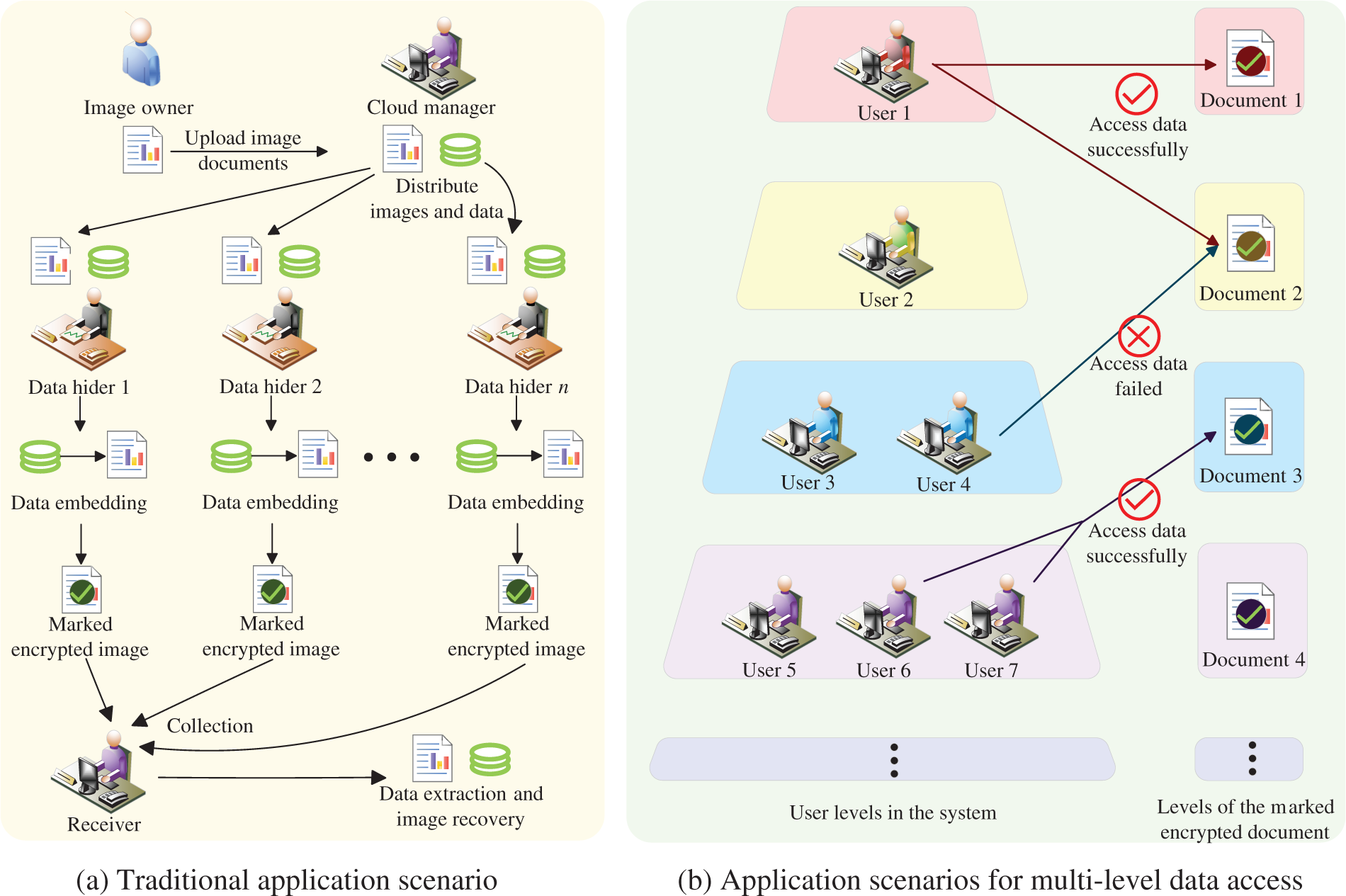
Figure 1: Application scenarios of RDH-EI algorithms
Hua et al. [28] introduced an RDH-EI method that utilizes feedback secret sharing to boost embedding capacity. Expanding on this research, Hua et al. [29] presented an additional algorithm that relies on matrix secret sharing, achieving effective ciphertext diffusion while preserving a high embedding rate, with information entropy nearing its theoretical peak. This method further strengthens the protection offered by current algorithms. In 2023, Yu et al. [30] integrated hybrid coding techniques into a secret sharing-based RDH-EI scheme, achieving an average embedding rate of 4.0531 bits per pixel (bpp). Hua et al. [31] introduced a preprocessing-free matrix secret sharing technique, enabling the RDH-EI scheme algorithm to circumvent the intricate process of handling overflow pixels. These advancements have enabled multiple data hiders to independently embed data. However, within most enterprise units in cloud service environments, users possess varying levels of access rights to enterprise data, particularly concerning sensitive internal information, which we refer to as “group’s secret data,” alongside other confidential data stored by users. Traditional data hiding algorithms based on secret sharing struggle to effectively address specific access policy dilemmas in such scenarios. As illustrated in Fig. 1b, there are primarily two issues: Problem 1 involves allowing high-level users to access low-level secret data while restricting low-level users from accessing high-level secret data, meaning that users should only be able to access data for which they are authorized. Problem 2 permits several low-level users to jointly access high-level confidential data that a single low-level user cannot access, provided certain threshold conditions are met. Traditional algorithms [25–29] do not offer solutions to these problems. In a multi-user environment, the only approach is to attempt to address these issues through key distribution methods. While this approach ensures data security, it significantly increases the number of keys required and consequently complicates key management. Furthermore, traditional algorithms lack the ability to differentiate between levels of data, resulting in all secrets being embedded by data hiders at the same level. This limitation is unsuitable for complex cloud service environments with multi-level user access requirements.
To address the challenges associated with complex multi-user access permissions, this paper proposes an RDH-EI method based on adaptive median edge detection (AMED) and ciphertext-policy attribute-based encryption (CP-ABE). We innovatively incorporate dynamic variables into the median edge detection (MED) predictor [32], proposing an AMED pixel prediction technique that offers improved accuracy. The algorithm encodes identical most significant bits (MSBs) between the predicted and target pixels, introducing random noise for image reconstruction and thereby producing a transitional image. User attributes and data access rights are leveraged to construct a robust access control framework. The transitional image is encrypted based on these user attributes, with varying levels of the group’s secret data embedded during the encryption process. This results in the production of an encrypted image that is distributed to the data hider. The data hider can then independently embed the secret data, resulting in a marked encrypted image. Upon decryption using the corresponding key, the receiver is able to extract the authorized secret data and the group’s concealed information, thus recovering the original image. Moreover, the receiver can grant access rights to others or collaboratively access the highest tier of the group’s secret data based on the established access control structure, and the algorithm effectively prevents unauthorized access. Experimental results demonstrate a significant enhancement in embedding capacity compared to existing algorithms [5,7,27–30]. Furthermore, this algorithm preserves the disaster-tolerant features inherent to the CP-ABE framework, enabling multi-level secure storage of carrier images and embedded information under secure multi-party conditions.
The key contributions of this paper include:
1. This paper presents the advanced AMED method, offering improved prediction precision compared to current MED prediction techniques [33]. By integrating dynamic variables, this method addresses the constraints of fixed predictors, effectively utilizing local texture features of pixel blocks for accurate predictions. As a result, we implement this technique to enlarge the embedding space.
2. Within the framework of attribute-based encryption, we creatively embed group’s secret data according to access levels. The embedded group’s secret data can only be extracted by users with the appropriate access rights, thus safeguarding data privacy. This algorithm is designed to be applicable within multi-level cloud service environments.
3. The proposed algorithm employs threshold characteristics to facilitate collaborative decryption. By appropriately partitioning user attributes, it effectively prevents unauthorized access. Furthermore, by utilizing a private key inheritance technique, the algorithm enables existing users to delegate part of their data access privileges to new users, thereby enhancing the flexibility of access control.
The structure of this paper is arranged as follows: Section 2 explores the theoretical foundations pertinent to the discussed algorithm; Section 3 outlines the specific implementation steps of the algorithm; Section 4 details the experimental procedure and results analysis; and finally, Section 5 wraps up with a conclusion and a perspective on future developments.
Pixel forecasting methods can rely on existing pixel values or other available data to estimate the value of the intended pixel. When the estimated value is similar to the intended pixel, pixel data can be compressed and stored utilizing encoding methods, resulting in additional space for embedding a significant amount of secret information. The median edge detector (MED), introduced by Li et al. [32], has gained widespread acclaim in numerous data hiding algorithms, attributable to its superior prediction accuracy and applicability [33]. This predictor exploits local pixel change characteristics for prediction. Specifically, it utilizes the surrounding three pixel values of the intended pixel y(a, b) to predict its value, as illustrated in Fig. 2, thus deriving the estimated value py(a, b). Eq. (1) delineates the precise computation process for the predicted pixel value.
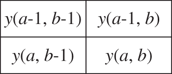
Figure 2: Chunking before pixel prediction
Li et al. [6] developed an RDH-EI method that minimizes image distortion using the MED pixel prediction technique to embed secret data by intelligently extending the prediction error post-image prediction. This algorithm boasts an embedding capacity of up to 6.5 × 104 bits while ensuring superior image quality upon recovery. Building on this success, Gao et al. [34] presented a scheme tailored for cloud environments leveraging MED technology, achieving a maximum embedding capacity of 906,494 bits. These algorithms collectively underscore the remarkable predictive efficiency of the MED technology. These algorithms rely solely on the correlation of local pixels to identify redundant space for embedding, overlooking the fact that each pixel block possesses unique texture characteristics. If the predictor can autonomously adjust to changes in pixel textures to enhance prediction accuracy, it can uncover more redundant space for embedding. To address this issue, the Adaptive Median Edge Detector (AMED) prediction method, presented in this paper’s algorithm, incorporates dynamic variables based on the MED prediction technique. This strategy removes the limitations of static predictors, notably improving pixel estimation precision and thereby increasing the embedding rate of the algorithm. When employing the AMED predictor, the cover image I is initially divided into T × T-sized blocks, which are then expanded as follows:
Step 1: If the block includes the pixel y(1, 1), no extension is performed.
Step 2: In the scenario where the pixel block lacks the x(1, 1) but includes y(1, b0) where b0 > 1, a set of random values is added to the adjacent side, enlarging it to a dimension of T × (T + 1).
Step 3: If the segment does not include image pixel y(1, 1) while comprising y(a0, 1) where a0 > 1, a set of random values is added above, increasing it to a block of dimensions (T + 1) × T.
For alternative scenarios: a set of random values is appended to the side and on top of the leftover pixel blocks, correspondingly enlarging them to a pixel block of dimensions (T + 1) × (T + 1).
The pixel y(a, b) of the i-th block is estimated utilizing the AMED to derive the estimated value py(a, b) illustrated in Eq. (2). First, we set the initial values for the dynamic variables combinations p1, p2, and p3 for prediction. The dynamic variables stay constant during the estimation of pixels within the same block.
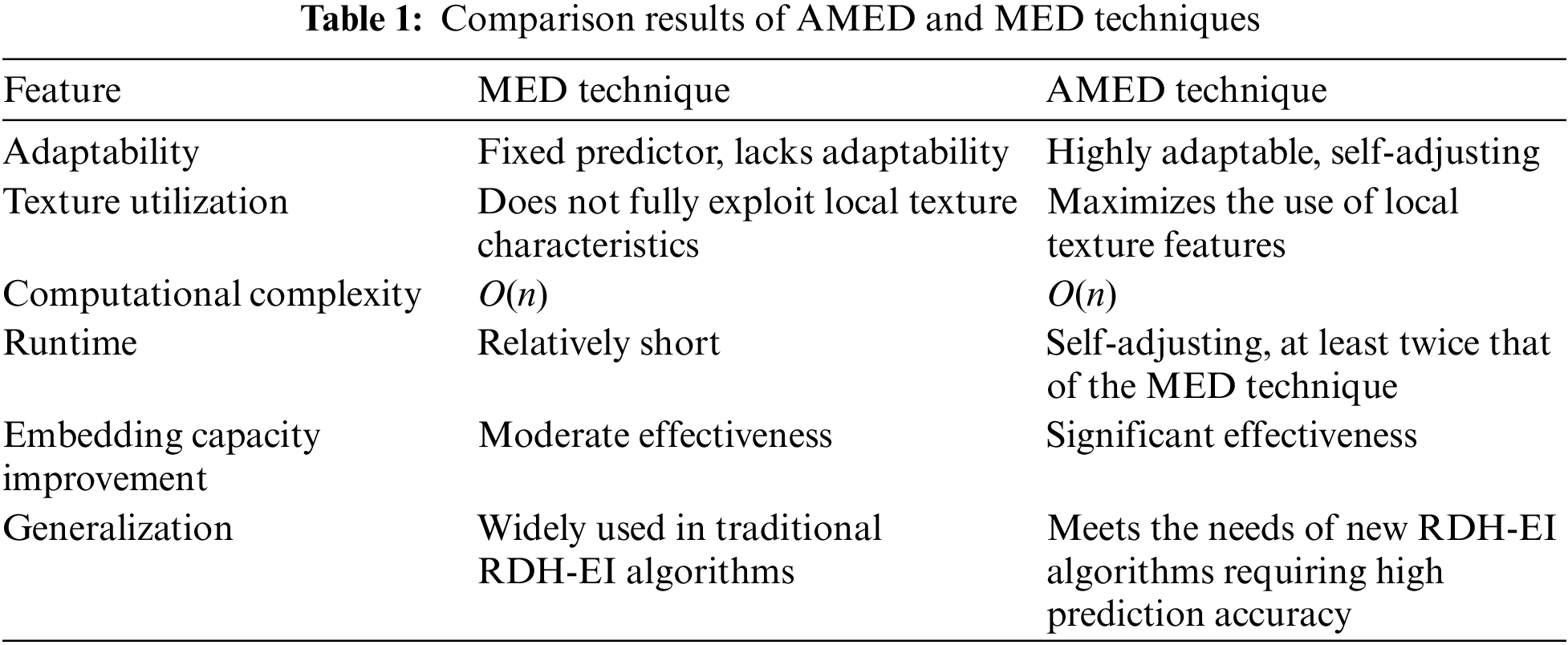
We estimate the values of every pixel inside the same block, enabling the predictor to engage in adaptive training customized for different situations. Based on the specific data embedding method, we calculate the embedding capacity of the pixel block to determine load(i). We then iterate through all possible combinations of dynamic variables values, repeating the prediction process to compute load(i). When this value reaches its maximum, we record the corresponding dynamic variables values at that moment. The predicted value py(a, b) p1, p2, p3 at this point is taken as the final predicted value. A comparative analysis of the AMED technique against the traditional MED technique is presented in Table 1. Assuming the data volume of the predicted image is n, it is evident that the AMED technique demonstrates greater practicality while maintaining the same computational complexity of O(n).
2.2 BSW Ciphertext-Policy Attribute-Based Encryption
Traditional RDH-EI algorithms face several challenges, particularly the increased burden of key management when attempting to implement multi-level data access via key distribution. In contrast, ABE technology emphasizes user attribute requirements over user identities and numbers within a group. This approach effectively reduces the total number of keys needed, simplifies management, and mitigates the risk of information leaks associated with improper key distribution. Additionally, ABE provides flexibility and enables fine-grained data access control, making it particularly suitable for various applications in multi-level cloud service environments.
In a study by Bethencourt et al. [35], the CP-ABE scheme was introduced to empower data owners to establish highly adaptable access policies, assign different access permissions based on user attributes, and enable fine-grained access control, playing a crucial role in safeguarding data security and privacy. The CP-ABE scheme encompasses five key algorithms:
Setup: Given a security parameter κ, this algorithm generates public parameters PK and master key MK.
Encrypt(PK, M, A) →CT: Using public parameters PK, plaintext M, and an attribute-based access structure A as inputs, this algorithm produces ciphertext CT.
KeyGen(MK, PK, S) →SK: By taking master key MK and attribute set S as inputs, this algorithm generates user private key SK.
Decrypt(PK, CT, SK) →M: With public parameters PK, ciphertext CT, and private key SK as inputs, this algorithm decrypts the ciphertext and outputs plaintext M if S satisfies A.
Delegate(SK,
The most crucial aspect of this process is the encryption of data using the access control tree and the allocation strategy of user attributes. We illustrate this concept by constructing an access control tree
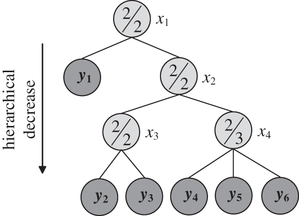
Figure 3: An example of an access control structure
In this research, a novel RDH-EI method is introduced, utilizing the inherent relationship among pixels and the encryption characteristics of attribute encryption to attain a substantial embedding capacity and layered data embedding. The framework of the method is depicted in Fig. 4, where the image creator produces a transitional image IR by predicting and encoding the source image I through the AMED approach and Huffman coding, followed by encryption via attribute encryption. During the encryption process, the algorithm selects embedding locations for the group’s secret data based on the access control structure A, which contains user attributes. The resulting encrypted image IE, after embedding, is then transmitted to the data hider. The data hider embeds the secret data to produce the marked encrypted image IM, from which an authorized receiver can extract the secret data matching their access permissions and recover the image. Furthermore, the system employs key inheritance and threshold properties to facilitate permission granting and joint decryption functions. This design enables multiple users to simultaneously access a broader array of the group’s secret data by providing their respective private keys for decryption.
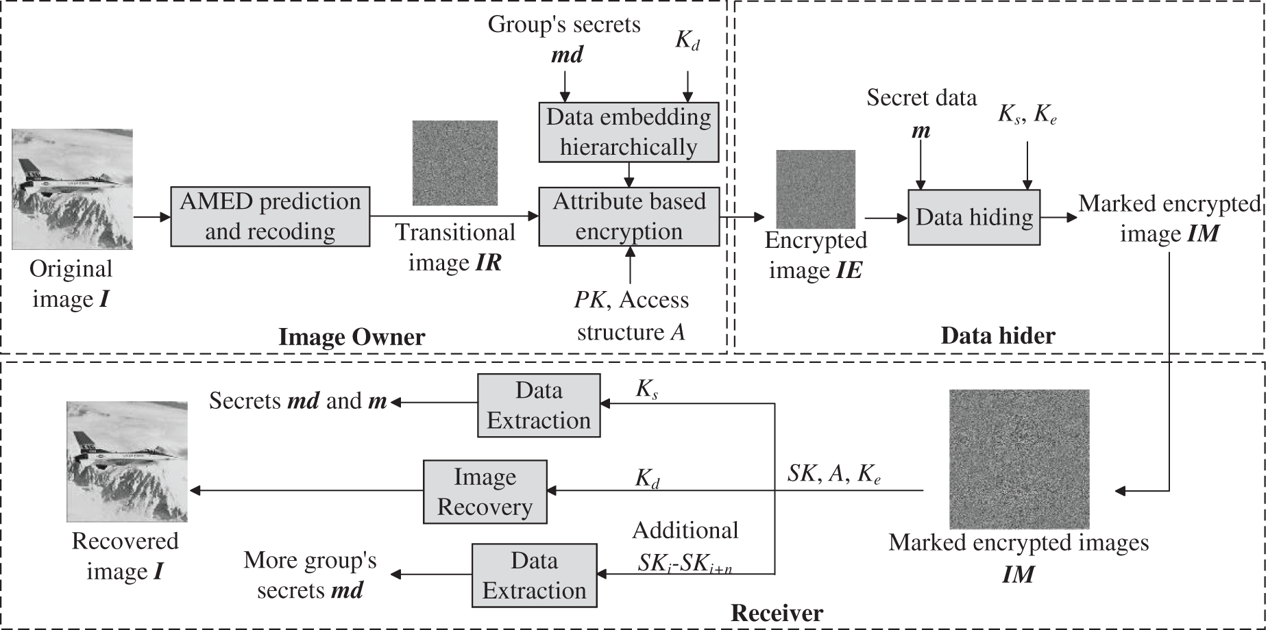
Figure 4: Flowchart of the proposed algorithm
3.1 AMED Forecasting and Re-Encoding
3.1.1 Segmented Pixel Forecasting
In order to optimize the use of pixel correlation for high-capacity embedding, we directly implement pixel estimation on raw images. First, the original image I, which has a size of M × N, is segmented into sections of size T × T, which results in a total of TM × TN sections, where T ≥ 3. The values of TM and TN are established by a specific formula detailed below:
Following the procedure described in Section 2.1, we adjust the pixel blocks to fit the AMED prediction requirements. The pixel at position y(a, b) within the i-th block is estimated with the AMED to determine the forecasted value py(a, b) as indicated in Eq. (2). At the start, the initial values for the dynamic variables p1, p2, and p3 are established, with the experimental phase setting these values to 0. The y(a, b) is transformed into an 8-bit binary string, according to Eq. (4).
In this context, yi(i, j) symbolizes the value derived from the k-th bit, beginning from the highest bit, with yi(a, b) belonging to the set {0, 1}. Likewise, the transformation of forecasted pixel values results in pyi(a, b), where i ranges from 1 to 8. By conducting a bit-by-bit comparison of yi(a, b) with pyi(a, b), starting from the most significant bit (MSB), we identify the span of matching sequential bits up to the first differing bit. This recorded value is denoted as u(a, b) and can take on values from 0 to 8, indicating the number of consecutive matching bits between yi(a, b) and pyi(a, b). If we consider the specified pixel y(a, b) = 172 and the forecasted value py(a, b) = 161, after converting them to binary strings (yi= {1 0 1 0 1 1 0 0} and pyi= {1 0 1 0 0 0 0 1}), a bitwise comparison reveals the first four bits to be identical, with the fifth bit differing, leading to a result of u = 4. Subsequently, the top five bits of the specified pixel are replaced numerically, enabling the insertion of confidential information, as depicted in Fig. 5 below.
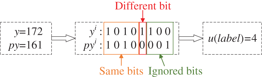
Figure 5: Example of a pixel tag
The AMED forecasting is carried out for each pixel in the pixel grid, excluding the first row and column. As a result, (T − 1)2 labeling values are derived, enabling the development of a complete labeling chart for the entire pixel grid.
3.1.2 Summation of Load Space by Regions
To compress the labeled values u, we utilize Huffman coding, incorporating nine distinct cases of u that correspond to nine unique Huffman codes. Each specific value of u is assigned a particular Huffman code for efficient encoding. In this encoding scheme, shorter codes are designated for labels that occur with higher frequency, while longer codes are allocated to those with lower probabilities. The set of Huffman codes employed includes {00, 01, 100, 101, 1100, 1101, 1110, 11110, 11111}, where “00” represents the most frequently occurring label and “11111” indicates the rarest.
Using the label u = 4 as a case study, through the prediction process, we determine the top 5 bits from the selected pixel to facilitate embedding secret data by replacing these bits. However, it’s essential to remember the label u with the designated encoding “00”. This consideration enables us to calculate the data storage potential for one pixel having the label number of 4: load(a, b) = 4 + 1 − 2 = 3. We can utilize Eq. (5) to calculate the storage capability of every image element.
Subsequently, the storage capability of all image elements within the section is calculated and summed up to yield the section’s total load capacity, represented as load(i). In the course of predicting image elements using fixed dynamic variables p1 = p10, p2 = p20, and p3 = p30, the load capacity loadp10, p20, p30(i) of the block is ascertained. Through adaptive training, the optimal parameter combination is determined by iteratively exploring all possible values of p1, p2, and p3 within specified ranges. With the parameter space set to 23 for this algorithm (−3 ≤ pi ≤ 4), there exist 24 potential combinations (3 × 8 = 24) yielding 24 distinct values for loadp1, p2, p3(i). When this data reaches its peak value, we document the related dynamic variables configurations, denoted as p1 = p1n, p2 = p2n, and p3 = p3n. Subsequently, we designate the pixel label values at this juncture as the definitive labels for the image elements within the block.
Using a similar approach, we adaptively predict all pixel blocks of the original image, yielding labels for all pixels, which we denote as dataset W. We record the best set of dynamic variables that maximizes the capacity utilization.
We begin by using 3 bits to denote the chunking parameter T and 20 bits to specify the image size L. Subsequently, 32 × TN × TM bits are allocated to store the dynamic variables ADV. The Huffman encoding rule (HER) is represented with 32 bits, and the width W is converted into a binary sequence WB, whose length WT is recorded using 22 bits. Finally, L, WT, T, ADV, HER, and WB are sequentially concatenated with the top and side pixel values of the source image to form the boundary data O.
Next, the boundary data O is embedded as follows: the first 8(M × N − 1) bits replace the top and side pixel values of the image. The remaining boundary data is embedded through bit substitution based on pixel labels, utilizing the (u + 1) most significant bits of the untouched pixels. The insertion procedure is mathematically expressed as:
Here, xe’(i, j) indicates the pixel intensity after the data has been embedded, sl signifies the supplementary data that can be inserted within the present pixel, and l serves as an abbreviation for the storage potential of an individual pixel. After the integration of all boundary data, we generate arbitrary noise which is then inserted into the leftover spaces subsequent to the boundary data, according to Eq. (6). This process results in the creation of the image IR.
3.2 Encryption of Carrier Data and Insertion of the Group’s Secret Data
We categorize the pixels in the image into distinct parts: Section A, which holds data L and WT; Section B, which includes the residual boundary data; and Section C, which covers all additional pixels. Selective encryption is then applied to Section B based on user attributes.
Firstly, we establish the access control policy A by constructing the access structure tree
Before performing encryption, certain variables must be defined. Firstly, we establish the bilinear group 𝔾0 of prime order p, where p = 730750818665451621361119245571504901405976 559617, and g serves as the generator of 𝔾0. The bilinear mapping is constructed as follows:
Subsequently, we generate the system’s public parameters and master keys. A prime of order p is chosen to form the bilinear group 𝔾0, with elements of order g. Parameters α and β are randomly selected from ℤp. The resulting public parameters are
In the following steps, we encrypt the group’s secret data md= {0, 1}N using the group’s secret data hiding key Kd. Each element is divided into segments of 159 bits, with a “0” padded at the beginning of each segment, forming the dataset M. Since elements in 𝔾0 are represented in 160-bit binary, we proceed with this approach to facilitate calculations during subsequent embedding processes.
We select a polynomial qx for each node x in the access control tree
For the root node R, we set qR(0) = s, where s is a random number from the domain ℤp. The polynomial for the root node is qR(z) = s + a1z + a2z 2+ a1z +…+ arR−1z rR−1 mod p. From M, we sequentially select nR−1 elements c1, c2, …, c rR−1 to embed into the polynomial coefficients:
This embedding phase includes data with the highest access level among the group’s secret data (denoted as mr), requiring the highest permissions. The root node resides at the first level, its children at the second level, and so on. The more layers in which the data is embedded, the higher the represented access level becomes.
Next, the remaining group’s secret data is embedded into non-leaf nodes following a breadth-first traversal order, excluding the root node. Taking node x as an example, when constructing its corresponding polynomial qx, we set qx(0) = qparent(x)(index(x)). We select nx−1 elements cu+1, c u+2, …, c u+rx−1 from M in sequence and embed them to form the polynomial:
For leaf nodes x, qx is set to qx = qparent(x)(index(x)) without polynomial construction. After traversing access tree
During the encryption process of each element in B2, we can embed multiple times to incorporate more data. After encrypting all elements, we proceed with splicing to obtain:
Here, att(y) denotes the attribute value for node y. CT is converted into binary data B3, from which pixels are selected and stitched with transitional image IR parts A and C to match the size of image IR. Remaining B3 pixels fill the expansion, resulting in encrypted image IE, which is then sent to the data hider for embedding.
We first encrypt the secret data m= {0, 1}N using the message hiding key Ks to obtain the encrypted data m’ = {0, 1}N. Next, we derive parameter L from the first line of the encrypted image, which represents the size of the original image. We then extract partial boundary data from pixels IE(1, b) and IE(a, 1). Thus, we obtain parameters WT, HER, T, ADV, and partial WB, alongside the section C size from image IR.
According to Eq. (4), we convert pixel values to 8-bit binary, based on the current segment of WB and following HER, to obtain label values for some pixels in the image. From the higher (u + 1) bits of these pixel values, we extract boundary data, which includes the label values for the next segment of pixels. Then, by using these newly derived label values, we repeat the process to extract new boundary data iteratively, completing the cycle to obtain complete enclosed boundary data. Then, we partition the image IEk into section A and C, and B3, substitute the partial pixel data of section C with m’i bit by bit, finishing the incorporation process to yield the image IA. Subsequently, IA undergoes dual encryption via scrambling and exclusive OR (XOR) operations to enhance security. Firstly, we partition the image IA into pixel segments of dimensions T × T. Using the key Ke, we produce a series of arbitrary numbers, which we subsequently arrange to obtain index vectors corresponding to the pixel blocks. Next, we reorder these segments based on the index vectors to create the image IE’. Subsequently, XOR encryption is applied: generating an M × N random matrix Pk based on the key Ks, encrypting image IE’ by the Eq. (12), and finally obtaining the marked encrypted image IM.
where ⊕ denotes modulo 256 addition, and i, j are position indices with 1 < i ≤ M and 1 < j ≤ N.
3.4 Data Extraction and Image Recovery
When we, as the receiver, decrypt the marked encrypted image IM, we begin by reversing the scrambling process and perform XOR decryption using the key Ks to recover the image IA. We then repeat the processes used in the secret data insertion stage to retrieve both the boundary data O and the data m’i. Ultimately, by decrypting m’i using the Ks, we obtain the mi.
The receiver initially generates their private key SK based on their own attributes using the public parameters PK and the system master key. MK Assuming the receiver’s attribute set is denoted by S, where S ∈ Sa, they select r randomly from ℤp. For each attribute j ∈ S, they select rj randomly from ℤp. This process generates the private key corresponding to the attribute set S:
Next, the receiver performs the secret data extraction phase on the marked encrypted image to isolate section B3 from the image and obtain the ciphertext set CT. The image recovery process employs a recursive algorithm, defined as DecryptNode(CT, SK, x), which executes the following operations on all nodes x within the access control tree:
a) When x is a leaf node with attribute i = att(x): If i ∈ S, we define:
When the attribute corresponding to private key SK does not belong to the set of attributes in the control structure (i.e., i ∈ S), the DecryptNode(CT, SK, x) algorithm outputs ⊥.
b) When x is a non-leaf node: For all child nodes w of node x, call DecryptNode(CT, SK, x) and store the result as Fw. Let Sx be any set of child nodes w of size kx satisfying Fw ≠ ⊥. We compute:
where i = index(z) and S’x = {index(w):w∈Sx}.
DecryptNode(CT, SK, x) is a recursive algorithm that operates in the reverse order of breadth-first traversal on all nodes of tree
Finally, B2 is computed using the following equation:
From BL in B2, extract section B. Concatenate parts A, B, and C of the image to obtain the transitional image IR. Replace the initial horizontal and vertical lines of IR using those from the initial image in boundary data O. Dynamic variables p1, p2, and p3 for pixel y’(a, b) are derived from dynamic variables ADV in O. Beginning at IR(2, 2), perform AMED estimation for pixel y’(a, b) in a fixed order to predict the intensity of py’(a, b). Using available u from boundary data, determine the pixel’s load for recovering original pixel value, ensuring the predicted pixel matches the initial pixel’s upper u MSB bits, with the opposite (u + 1)-th MSB position. The restoration procedure is as follows:
Once all pixels have been successfully restored, the original image I is recovered.
3.4.3 Group’s Secret Data Extraction
We obtained CT in the previous step, from which we isolated the qy values corresponding to each leaf node in tree
Set zi denote the index value index(xi). It is known that node xi satisfies the polynomial:
We reconstruct the polynomial qy using Lagrange polynomials:
We extract the coefficients ci to retrieve encrypted secret data M. By performing these operations on all non-leaf nodes and decrypting the extracted data using the key Kd, we obtain all the group’s secret data that the receiver is authorized to access.
Based on the keys in possession, the recipient is able to independently perform secret data acquisition, reconstruct images, and extract group’s secret data.
3.5 Joint Decryption and Permission Granting
The algorithm proposed in this paper, due to its threshold encryption and key inheritance properties, features both joint decryption and permission granting functionalities.
Using the access control policy illustrated in Fig. 3 as a case study, consider User ID1 with attribute value att(y2, y4), unable to extract the group’s secret data mdx3 from the root node x3. Similarly, User ID2 with attribute att(y3, y6) also lacks access to this data. However, users ID1 and ID2 can simultaneously provide qy2(0) and qy3(0), thereby deriving the polynomial qx3(z) from Eq. (19) and extracting group’s secret data mdx3 from the polynomial coefficients. To prevent unauthorized access, if users ID1 and ID2 are not permitted joint access to data in the root node x1, the attribute att(y2) is not assigned. Only with the involvement of a third user possessing att(y2) during decryption can the threshold requirement be met for successful data access. This mechanism allows the system to flexibly control user permissions for data access, achieving fine-grained access control.
The system supports users granting permissions to others, facilitating flexible sharing. This involves a legitimate user generating a lower-permissioned private key to bestow upon a new user, allowing access to lower-level group’s secret data.
For instance, User ID1, holding attribute set S and private key
Taking the access control policy illustrated in Fig. 3 as an example, User ID1 possesses the attribute set att(y1 − y6), which enables access to data embedded across all nodes in the tree
4 Experimental Investigations and Outcome Assessments
To assess the performance of the method and highlight improvements compared to current approaches, we randomly chose 21,338 monochrome images from various datasets: BOSSBase [36], BOWS-2 [37], and UCID [38], for comparative experiments. Some sample images used are depicted in Fig. 6. Our assessment of the algorithm in this study covers three aspects: reversibility, embedding capacity, and security. The experimental setup utilized an Intel® Core™ i7-13650HX CPU, 8 GB of RAM, Windows 11 as the operating system, and MATLAB R2021a as the simulation platform.
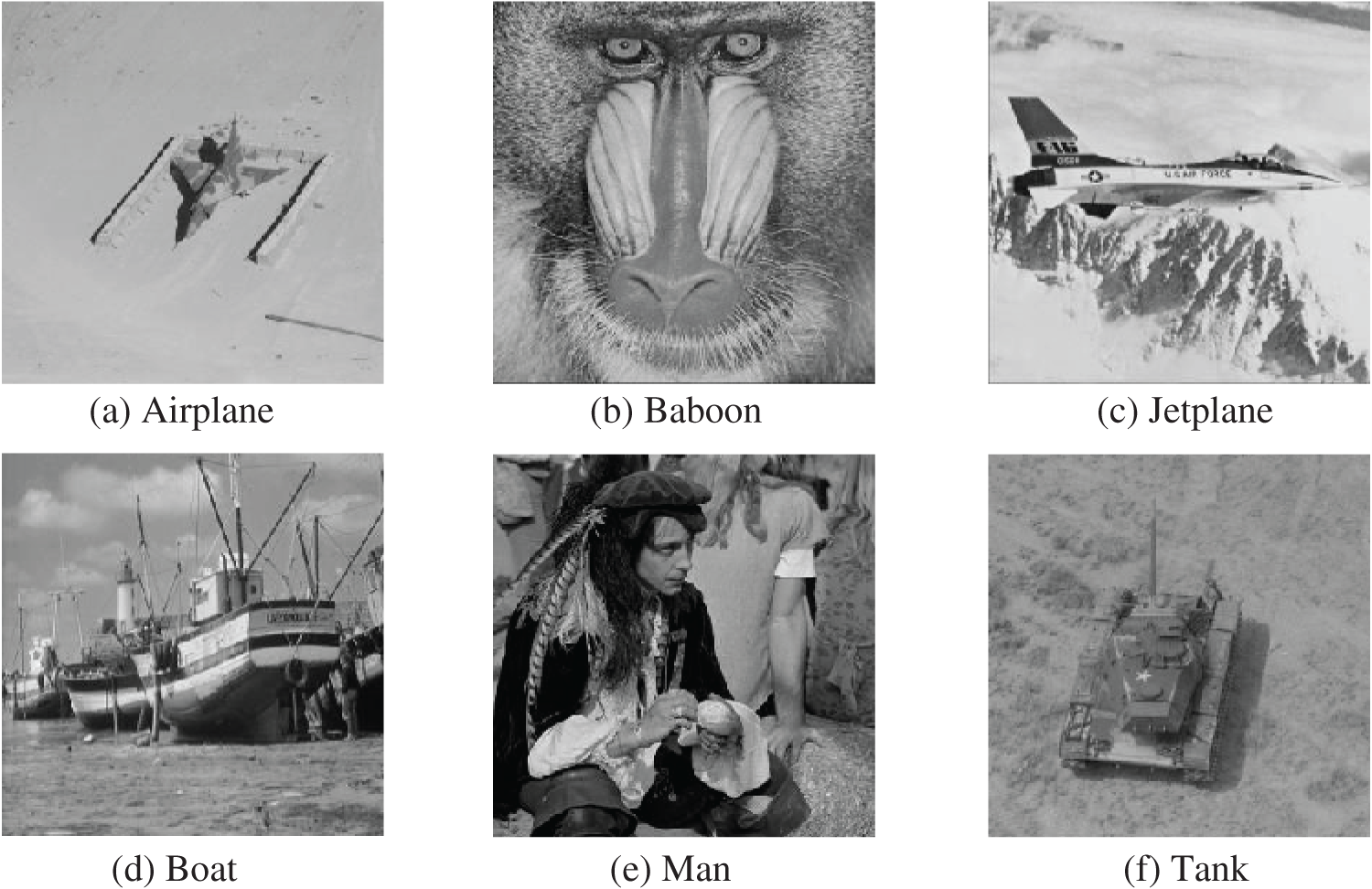
Figure 6: Some of the carrier images used in the experiment
In this study, we conducted an embedding simulation experiment using the Tank image with our proposed algorithm, which is based on a (3, 4)-threshold and a three-layer access structure. Fig. 7 illustrates the visuals produced throughout the experiment: Fig. 7a presents the source image, while Fig. 7b displays the transitional image produced by pixel estimation and compression. Fig. 7c illustrates the secured image infused with randomized group’s secret data, and Fig. 7d depicts the labeled secured image created following the incorporation of the randomized group’s secret data, where it is clear that no detectable details regarding the confidential information or the source image are perceivable to the human eye. Finally, Fig. 7e displays the reconstructed image.
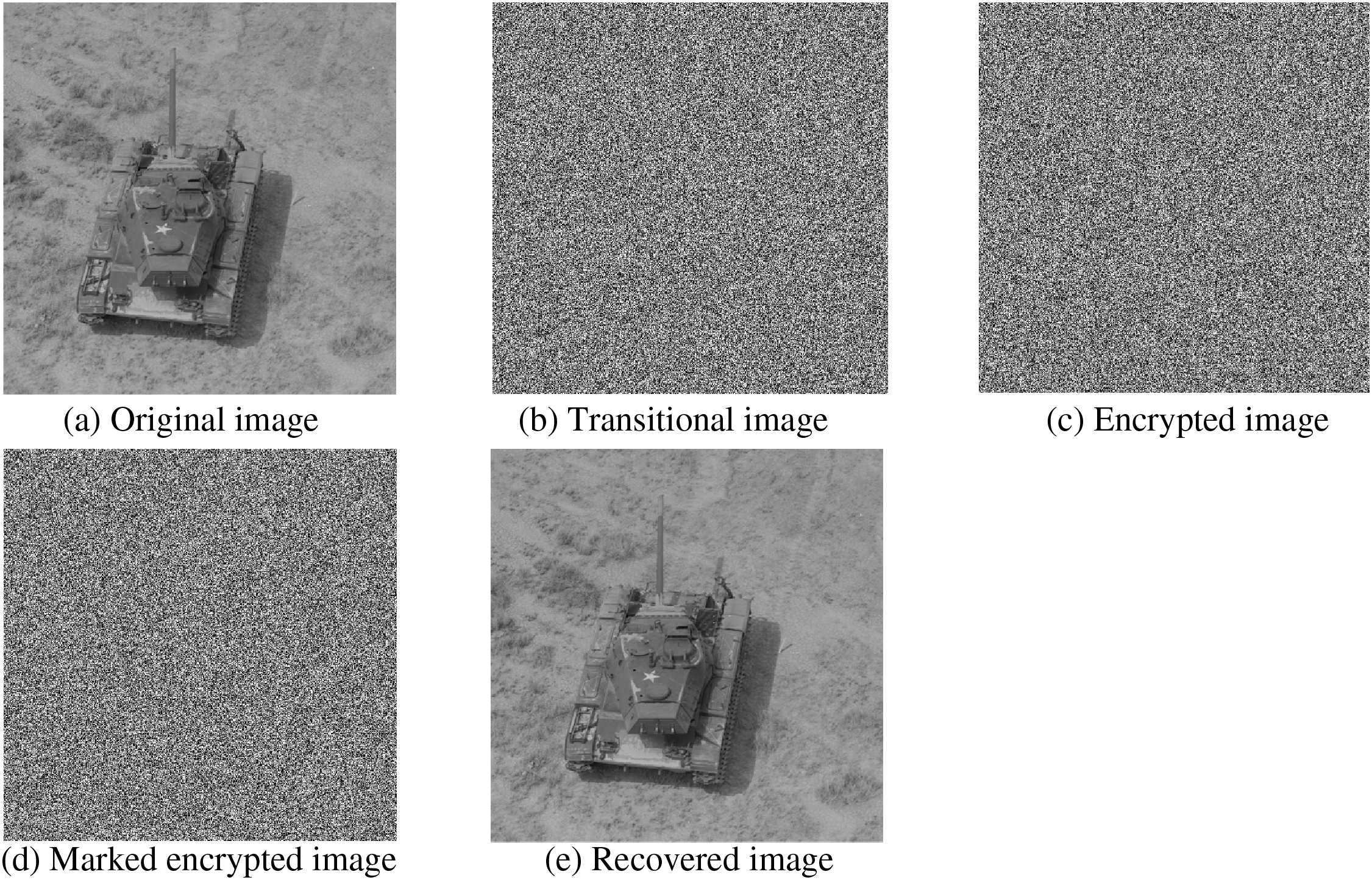
Figure 7: Visuals produced at different phases throughout the experiment
To evaluate the distortion in visual recovery caused by the algorithm, we measure the peak signal-to-noise ratio (PSNR) for benchmarking purposes. PSNR quantifies the accuracy between the restored visual and the source, reflecting the algorithm’s reversibility. Generally, when PSNR tends toward infinity, it indicates nearly flawless restoration of the original image. The computation of PSNR is performed using the formula below:
where i represents the image pixel depth of 8 bits, MSE can be obtained using the formula provided below:
Here, Ta,b and T’a,b correspond to the pixels of the original and restored images, in that order, with N and M representing the dimensions of the image.
Fig. 8 shows a comparison of the rate-distortion plots for different methods applied to the Tank image. The method by Li et al. [6] induces image distortion due to insufficient utilization of pixel correlation during image recovery, achieving a PSNR of only 54.51 dB at an embedding rate of 0.25 bpp. Chen et al.’s algorithm [18], leveraging MSB correlation compression for embedding, maintains a PSNR above 50 dB at embedding rates below 0.5 bpp; however, the PSNR decreases rapidly beyond 0.5 bpp. This is attributed to embedding 3 bits of data with 7-bit matrix coding, resulting in partial distortion during restoration. Zhang et al.’s algorithm [23] for image restoration, utilizing the weight prediction technique, selectively handles pixels and lacks sufficient boundary data to store prediction errors, limiting its reversibility. Ke et al.’s method [24] flips the least significant bit (LSB) during image recovery, leading to partial distortion in the recovered image. Xiong et al.’s algorithm [27], which employs Lagrange interpolation for pixel recovery, is prone to bit flips and image distortion. In contrast, our algorithm has been validated through Matlab simulations, achieving infinitely high PSNR values. In our encrypted image processing approach, we encode the prediction error using Huffman coding following the image prediction phase. This accurate decoding ensures complete recovery of the target pixels via the AMED pixel prediction technique, thereby guaranteeing full reversibility of the image recovery process. Additionally, the reliability of the decryption process for attribute encryption further reinforces the reversibility of our proposed algorithm. Thus, when contrasted with current algorithms, the method introduced in this study is the best for image quality restoration, achieving a PSNR that approaches infinity, which enables complete lossless recovery of the original image.
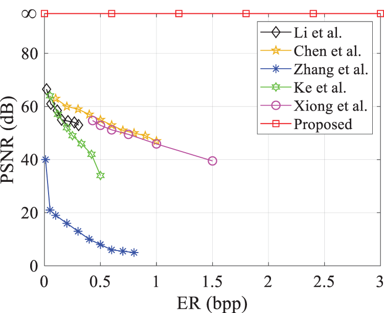
Figure 8: Plot of PSNR vs. embedding rate on tank image for this paper’s algorithm and existing algorithms [6,18,23,24,27]
The volume of data embedded within an image functions as an essential criterion for evaluating the performance of a data hiding method. We utilize the embedding rate (ER) as a metric to quantify the mean quantity of data that can be incorporated into each pixel of a given image, defined by the following equation:
If the data hider only allows the receiver to extract data without enabling them to recover the carrier image, they can omit storing the information needed for image recovery during the encryption phase. Referring to Eq. (10), we modify the scheme to involve only
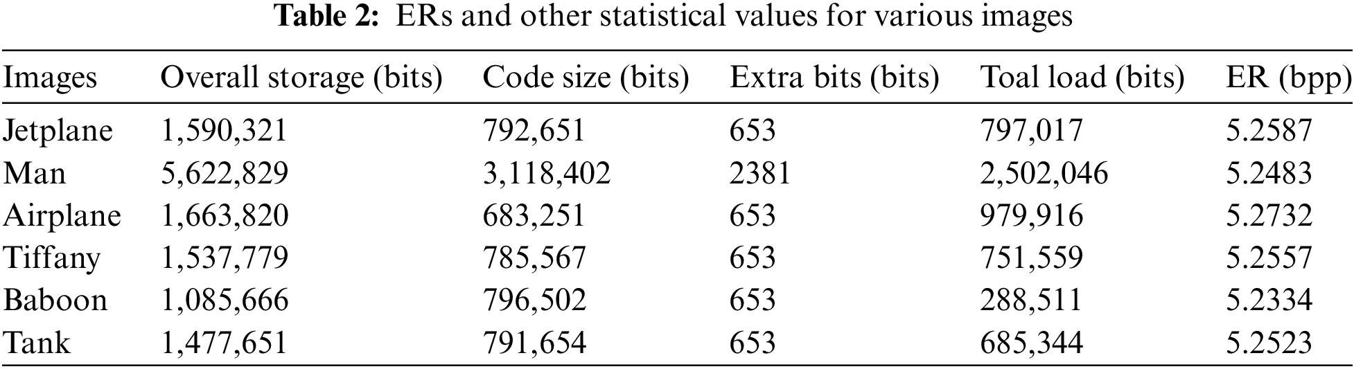
The embedding of secret data occurs post reception of the encrypted image by the data hider, achieved through replacing bits in the noisy regions of the image. The volume of embedded data is linked to the storage capacity of the transitional image. Table 2 illustrates algorithmic storage capacities across various images under T = 64 conditions. Here, image load capacity isn’t simply the aggregate of pixel block capacities, as additional space is required to store boundary data essential for guaranteeing the method’s ability to completely restore the original image. Table 2 highlights varying storage capacities among different visuals as a result of unique texture characteristics. Utilizing our proposed algorithm, based on (3, 4)-threshold and a 3-layer access structure for image embedding, demonstrates varied embedding rates across these images.
To assess the general embedding ability of our algorithm, images in grayscale with dimensions of 512 × 512 from the BOSSBase [36] and BOW-2 [37] collections, as well as 1338 monochrome images from the USID [38] collection, and embedded randomly generated data into them. The findings from the experiments are presented in Table 3. Under the 3-layer system access control structure, the lowest embedding rate of our method based on (3, 4)-threshold surpasses 4.5 bpp. Based on (6, 6)-threshold, the lowest ER is above 7.0 bpp, and the average rate is above 7.5 bpp. The algorithms exhibit infinite PSNR, guaranteeing reversibility. Performance graphs illustrating ERs for the different image collections are shown in Fig. 9.
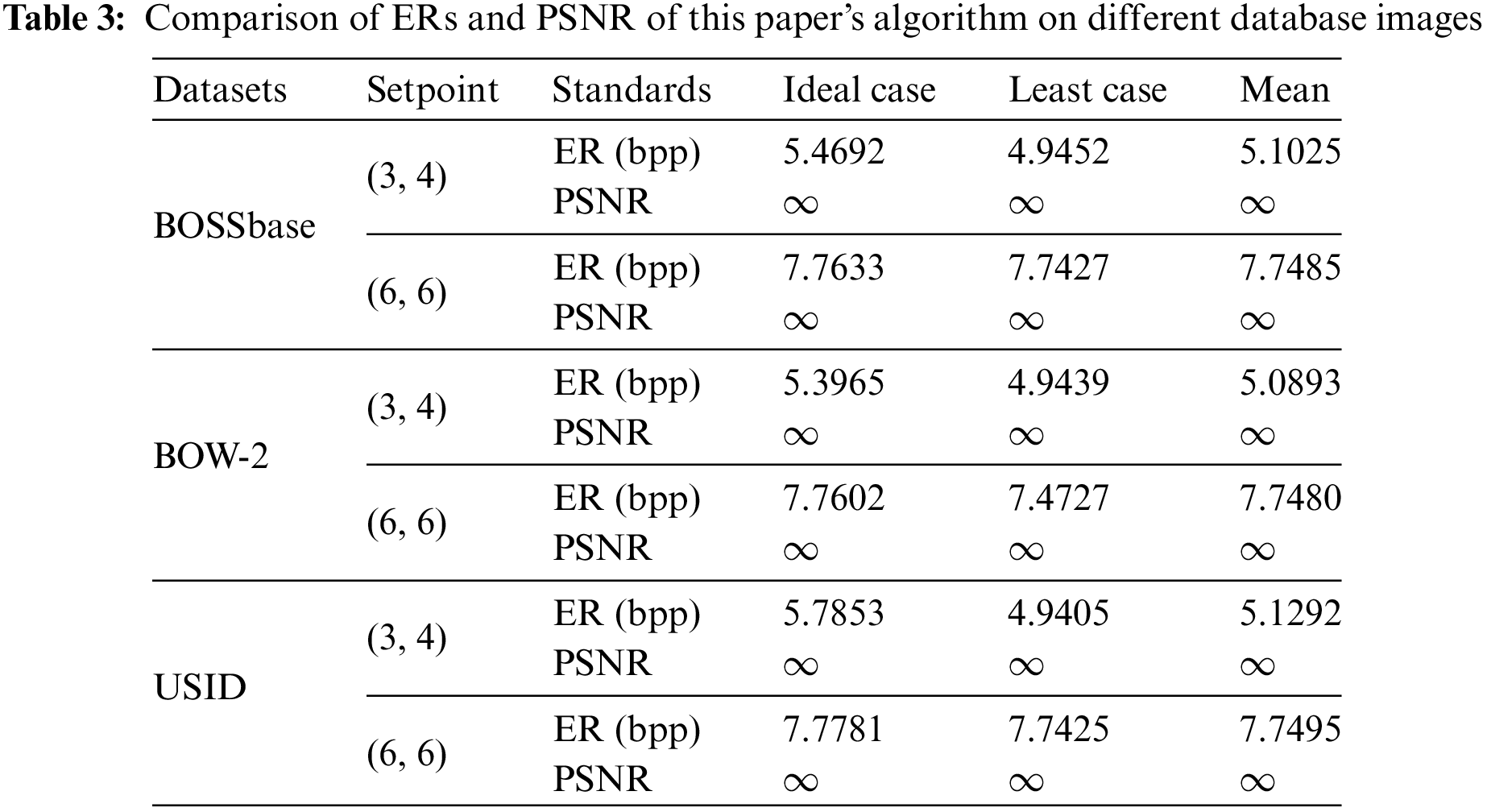
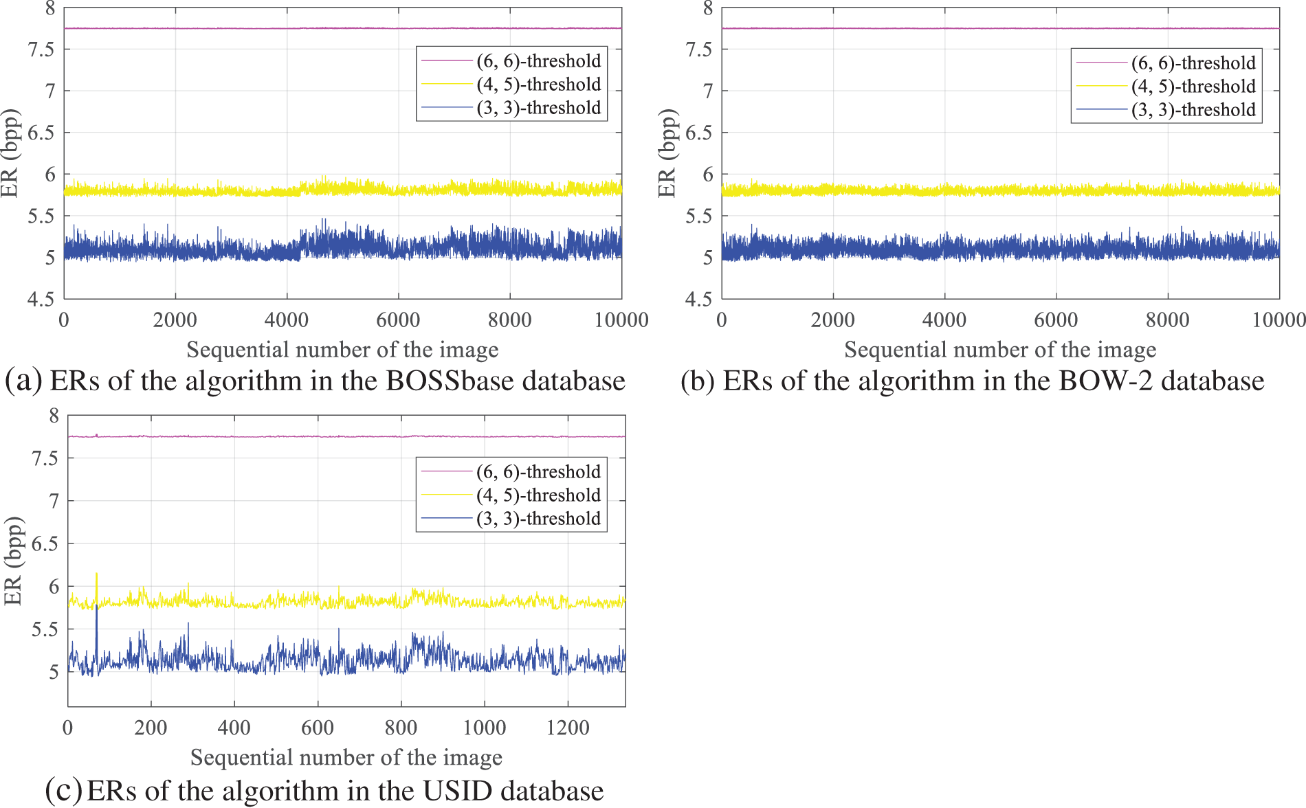
Figure 9: ERs of this paper’s algorithm on different database images
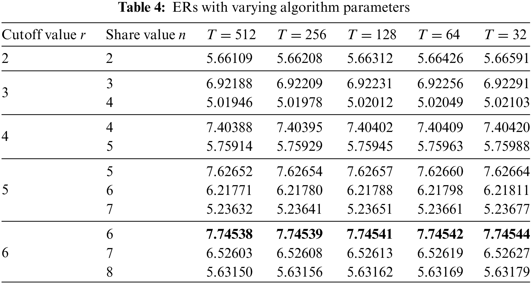
Next, we investigate how the threshold value of our algorithm influences the ER of images. Table 4 demonstrates the comparison of ERs under different parameter conditions of our algorithm based on 3-layer access structure, as applied to embedding experiments on Man images. Based on the experimental outcomes, it becomes apparent that, given a constant cutoff value, reduced chunk dimensions lead to elevated algorithm ERs. This outcome stems from AMED prediction being based on texture features of various chunks, where smaller sizes enhance prediction accuracy. Additionally, with a constant chunk size, increased values of r result in greater ERs while n remains unchanged. Similarly, lower values of n result in higher embedding rates when r is constant. Our method attained a peak ER of 7.0659 bpp during the test. For practical use, it is crucial to select the values of r and n as closely as feasible to balance both robustness and a high ER.
To demonstrate the superiority of our algorithm in terms of embedding rate, we conducted experiments using several commonly used images. We evaluated the maximum embedding rates obtained by our method against current methods, as illustrated in Fig. 10. Puyang et al.’s algorithm [5] successfully embeds data into the two-MSBs but achieves only an average embedding rate of 1.1106 bpp due to embedding location constraints. Panchikkil et al. [7] predict pixel directions using snake scanning to select embeddable pixel blocks based on prediction errors, embedding secret data into pixel MSBs. Their algorithm achieves an average embedding rate of 1.3505 bpp while ensuring reversibility. In contrast, our algorithm achieves an average embedding rate of 7.7453 bpp while maintaining reversibility. Xiong et al.’s algorithm [27] achieves the highest embedding rate of 3 bpp at a PSNR of 20 dB, whereas our algorithm achieves the highest average embedding rate of 7.7781 bpp in experiments, approximately double that of Xiong et al.’s algorithm. Hua et al.’s algorithms [28,29] utilize the correlation of residuals from the sub-secret image for embedding, but their embedding rates are limited by the use of single coding techniques. Yu et al.’s algorithm [30] is enhanced by incorporating a hybrid coding technique, which improved the embedding rate to an average of 3.21 bits per pixel under a (3, 4)-threshold. In contrast, our method increases the embedding rate by approximately 1.93 bpp compared to Yu et al.’s algorithm. Therefore, compared to existing algorithms, the method presented in this paper is the best in terms of embedding rate, significantly outperforming existing algorithms under the same threshold conditions. Moreover, the embedding rate of this algorithm, based on a (6, 6) threshold, exceeds 7 bpp, which is nearly twice that of existing algorithms.
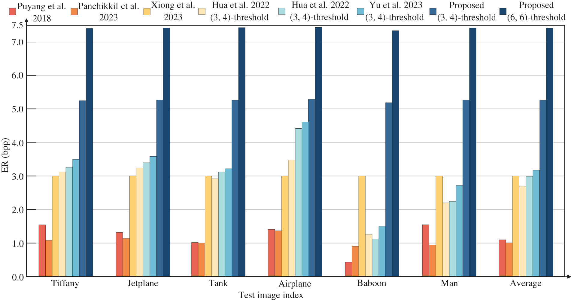
Figure 10: Assessment of ERs between the proposed method and conventional methods [5,7,27–30]
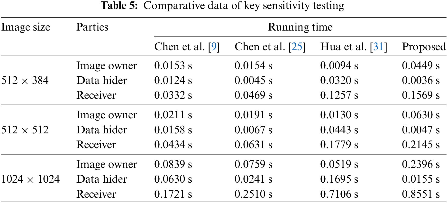
The running speed of an algorithm can reflect its practicality to a certain extent. In this study, we compared the running times of existing algorithms in a distributed environment with the algorithm proposed in this paper. To ensure fair testing, we fixed the threshold to (4,4) and set the embedding rate to 0.4 bpp. Using the proposed algorithm, which is based on a three-layer access structure, we embedded random data into images of varying sizes and recorded the running times. The results were compared with those of other algorithms under the same conditions, as shown in Table 5. The results indicate that all algorithms completed their operations in less than 1.0 s. Notably, our algorithm required less time to embed data compared to the other algorithms, demonstrating faster performance. However, the time needed for image encryption and data processing by the receiver was slightly longer than that of the other algorithms. This is due to our algorithm’s need to perform different operations based on user attributes and data access levels during the encryption, decryption, and data extraction processes, enabling fine-grained access control—a feature that other algorithms lack. In practice, cloud servers typically have substantial computational capabilities, providing sufficient resources to support the normal operation of the proposed method. To summarize, the method proposed by Hua et al. [31] is the fastest for image encryption, while the algorithm by Chen et al. [9] excels in image recovery and secret extraction. In contrast, the method presented in this paper offers the fastest data embedding speed, facilitating user storage of secret data.
The security of the proposed method in this study is based on the principle that unauthorized individuals are unable to derive any significant data from the marked image without possessing the correct key. Furthermore, the algorithm effectively restricts legitimate users from accessing group secret data beyond their authorized permissions.
The legitimate key Ks is required for an authorized user to retrieve the confidential data m from the encrypted image with markings, which is infeasible for attackers to extract correctly. Should an adversary succeed in obtaining the encrypted message m’ from the image IM1, the fabricated key will decrypt m’ and compare it with m bit by bit. If the values are identical, the outcome is recorded as 0; if not, it is recorded as 1. The results of the experiment are illustrated in Fig. 11a, where the probabilities for both outcomes are 0.5 and are statistically uncorrelated. Once the decryption key Ks is furnished by the recipient, the derived data corresponds to the initially embedded secret, as shown in Fig. 11b. This confirms that the attacker is unable to extract meaningful information out of the marked image without Ks. In this algorithm, the AES encryption scheme with a key length of 256 bits is utilized for stream key encryption of images and data. When performing scrambling encryption on an image of size M × N, the key space varies with the number of blocks TM × TN. If the access control structure includes m attribute selections, the total key space reaches
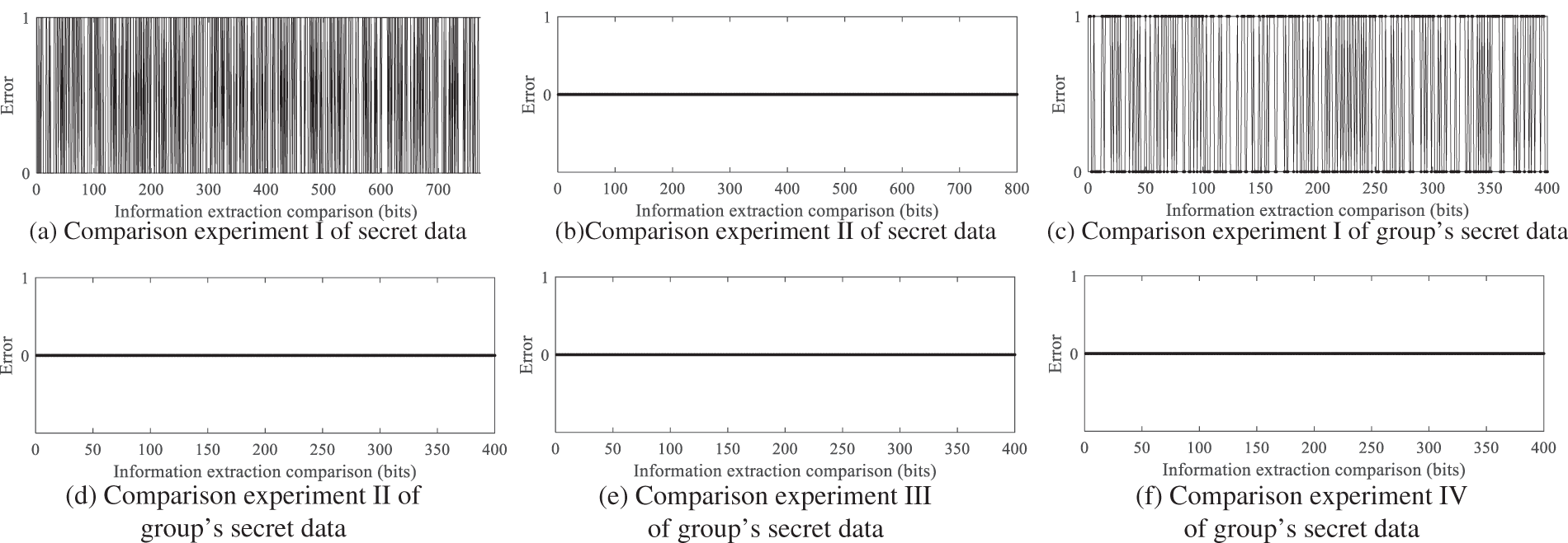
Figure 11: Experimental analysis of data retrieval compared to prior-integrated data
When two users decrypt jointly, more group’s secret data can be extracted. Now take the access control structure shown in Fig. 3 as an example: the set of attributes corresponding to the private key SK1 of User ID1 is att(y2, y4, y5); the set of attributes corresponding to the private key SK2 of User ID2 is att(y3, y6); and the set of attributes corresponding to the private key SK3 of User ID3 is att(y1 − y6). Now, when User ID1 and ID2 perform joint decryption, they extract the group’s secret data embedded in x2 from IM1, decrypt it with Ks, compare it with the group’s secret data before embedding, and the results are shown in Fig. 11c; the two are identical. When they attempt to access the group’s secret data embedded in node x1 by overstepping their authority, the group’s secret data is extracted and compared with its state before embedding, as shown in Fig. 11d. It can be seen that no valid information about the group’s secret data mdx1 can be extracted.
When User ID3 extracts the group’s secret data embedded in nodes x1 and x2 from IM1 respectively and compares it with the pre-embedding state, the results are shown in Fig. 11e,f. User ID3 successfully extracts the group’s secret data. The experiments demonstrate that authorized users in the system can correctly extract the group’s secret data they are permitted to access, based on their private keys, thereby achieving fine-grained access control. Additionally, the system effectively prevents unauthorized access by appropriately partitioning attributes.
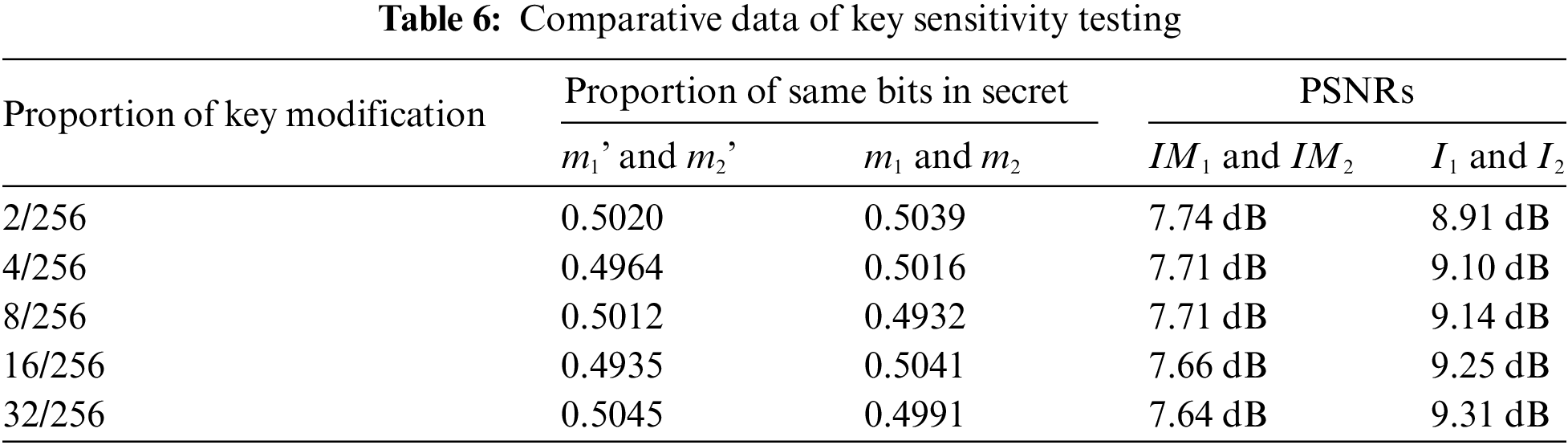
We conducted a sensitivity test on the algorithm’s keys, with the results shown in Table 6. Initially, we used the key Kd1 to encrypt 2000 bits of data to be embedded, denoted as m1, resulting in m1’. We then divided Kd1 into groups of 256 bits, randomly modifying the same number of bits within each group before re-encrypting m1 to obtain m2’. By comparing m1’ and m2’ bit by bit, we calculated the proportion of matching bits, which consistently hovered around 0.5. Next, we utilized key Ks1 and the modified Ks1 to encrypt image I1 while embedding m1’, resulting in the encrypted images IM1 and IM2. The PSNR values of both images were tested and found to be below 8 dB, indicating significant discrepancies between them. This illustrates that the key possesses extremely high sensitivity during the encryption process. Subsequently, we extracted and decrypted m1’ from IM1 using the modified key Ks1, yielding m2. A bit-by-bit comparison between m1 and m2 revealed that only around 50% of the bits matched. Furthermore, by decrypting IM1 with the modified Ks1, we obtained image I2, and the PSNR between I1 and I2 was again found to be below 10 dB, indicating that the modified key cannot accurately restore the original image. Therefore, even minor changes in the key can lead to substantial impacts on both the encryption and decryption processes. The high sensitivity of the key ensures the security of the stored data.
To prevent adversaries from retrieving usable information from the encrypted image with markings, its digital attributes must be consistent with those of random noise. We conducted experimental analysis from three fundamental angles: pixel arrangement, statistical dependencies, and informational entropy. The proposed algorithm, based on (3, 3)-threshold and 3-layer access structure, is used to embed randomly generated group’s secret data and users’ secret data into the Tank image. We examined the pixel distribution of relevant images in the experiment, with the results shown in Fig. 12. Visual observation reveals that the pixel distributions of the transitional image, the encrypted image, and the marked encrypted image are all uniform. To further analyze this, we conducted a chi-square test to assess whether the histograms of these images follow a uniform distribution. We first repeated the previous experiments to obtain more samples for testing, assuming that the tested images do not differ from the ideal condition of a uniformly distributed grayscale image. The expected frequency for each pixel value is 1/256. We then calculated the chi-square statistic using the Eq. (25).
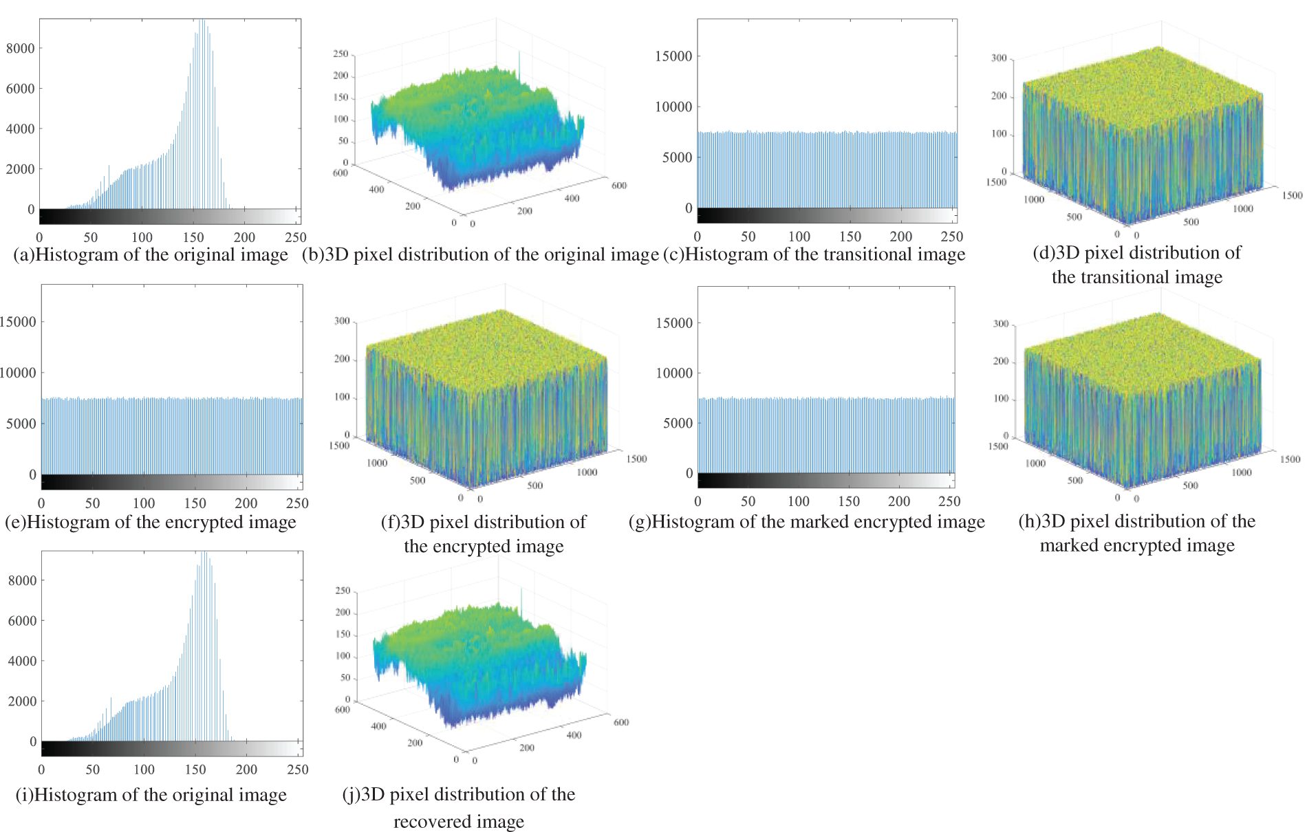
Figure 12: Pixel distribution of images at each stage of the experiment
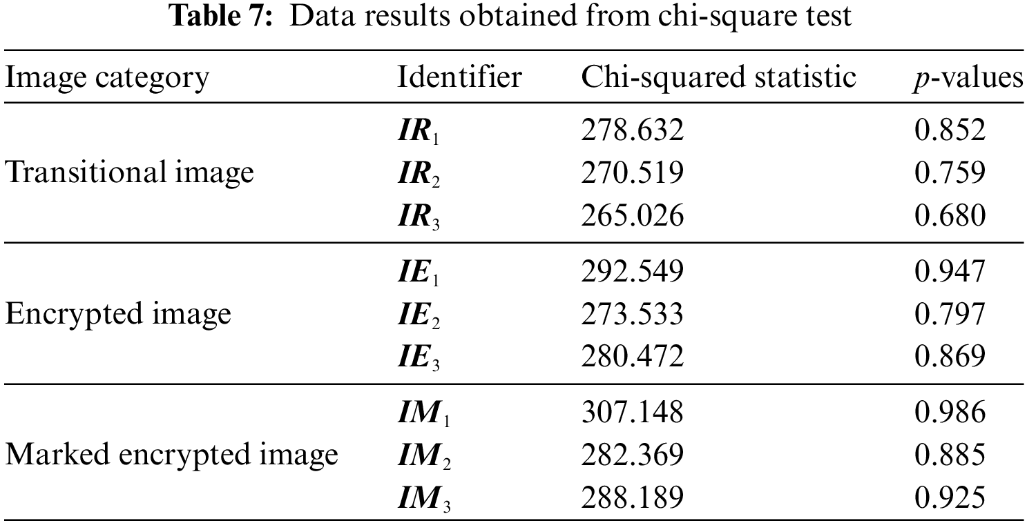
Here, Oi represents the observed frequency, and Ei denotes the expected frequency. Next, the corresponding p-value is obtained based on the degrees of freedom of 255, as shown in Table 7. The p-values for the tested images were all significantly greater than the critical value of the significance level (0.05), leading us to not reject the null hypothesis. Therefore, we conclude that the pixels of the transitional image, the encrypted image, and the marked encrypted image exhibit a uniform distribution.
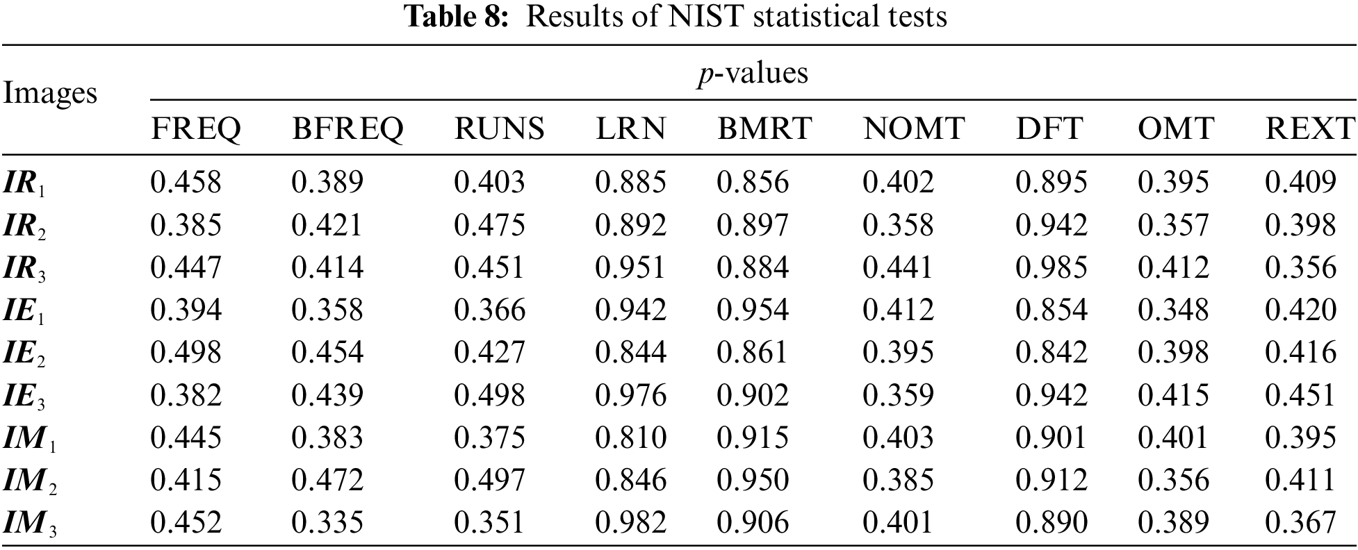
Next, we converted the marked encrypted images into a binary sequence, assuming that the image can be considered random. We then conducted NIST tests to evaluate the randomness of this sequence, with the experimental results outlined in Table 8. The p-values are all significantly greater than the significance level of 0.05, leading us to accept the null hypothesis. We conclude that the ciphertext demonstrates good randomness after passing the Frequency Test (FREQ), Block Frequency Test (BFREQ), Runs Test (RUNS), and other tests.
Next, we utilize a pixel association evaluation technique to randomly choose 20,000 adjacent pixel pairs from both the source image and the annotated encrypted image. We calculate the correlation coefficients along their horizontal, vertical, and diagonal directions using the Eq. (26) for correlation coefficient rxy, with x and y denoting the adjacent pixel intensities in the test image.
Table 9 presents the outcomes of the correlation coefficient analysis obtained from the embedding experiments conducted on Tank image. The marked encrypted images denote images encrypted with distinct attribute sets. The analysis demonstrates that the original images display a high level of correlation across multiple orientations, with an average coefficient of 0.9698, closely approaching 1. In contrast, the correlation values for the highlighted encrypted images tend towards zero. Fig. 13 presents a scatter plot comparing the correlation coefficients of the original image I to those of the marked encrypted image IM. It demonstrates that most sampling points for the initial image group closely along the line y = x, reflecting a high degree of correlation. Conversely, the scatter diagram of correlation values for the highlighted image displays a consistent distribution, in line with the quantitative and analytical properties of the noise-like monochromatic image. This result stems from the process of embedding confidential information into the image, which interferes with the pixel correlations. Subsequently, the image undergoes encryption using a stream cipher, further reducing the pixel correlation coefficient to nearly 0.
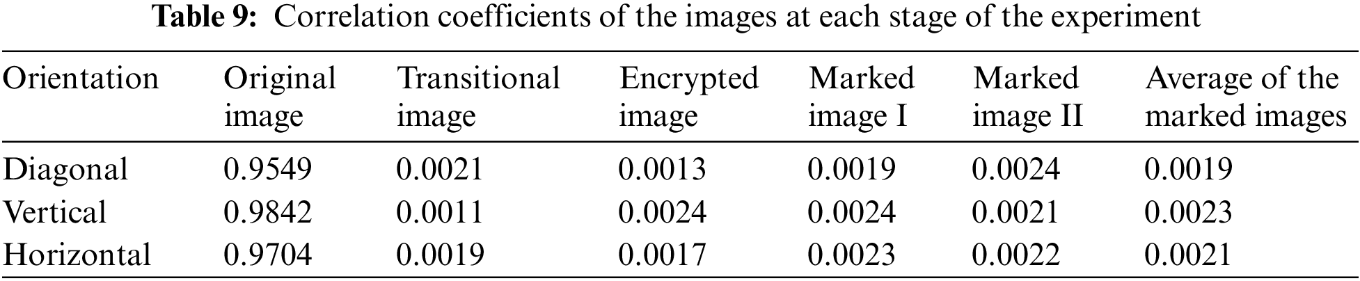
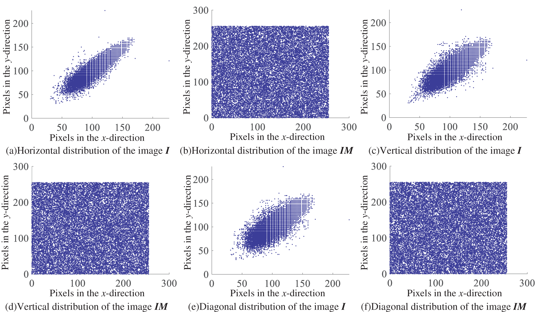
Figure 13: Scatter chart depicting the correlation metrics of evaluation images
The entropy of an image indicates the evenness of its pixel intensity distribution. Greater entropy signifies enhanced resistance to statistical attacks. It is determined through the following formula:
where N is the number of pixel values, and σi and Pr(σi) represent the i-th pixel value and its probability of occurrence, respectively.
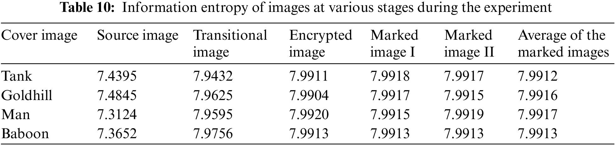
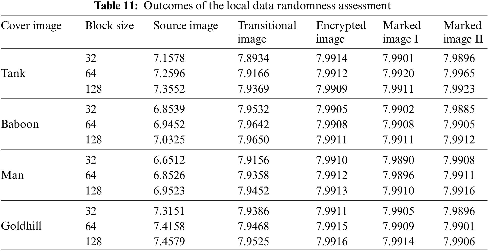
In an 8-bit grayscale image, where pixel intensities σi range from [1, 255], the entropy achieves its peak value (H = 8) if each pixel intensity occurs with a probability of 1/256. We evaluated the total information entropy for the test images, as detailed in Table 10. The mean entropy for the labeled encrypted images was 7.9914, which is close to the theoretical maximum value. We then randomly selected pixel blocks of various sizes from these images to perform a local information entropy test. The results, as shown in Table 11, indicate that the entropy of the marked encrypted images is close to 8. This suggests an almost even spread of pixel intensities, which helps protect the image from statistical attacks, guaranteeing strong security for hidden data.
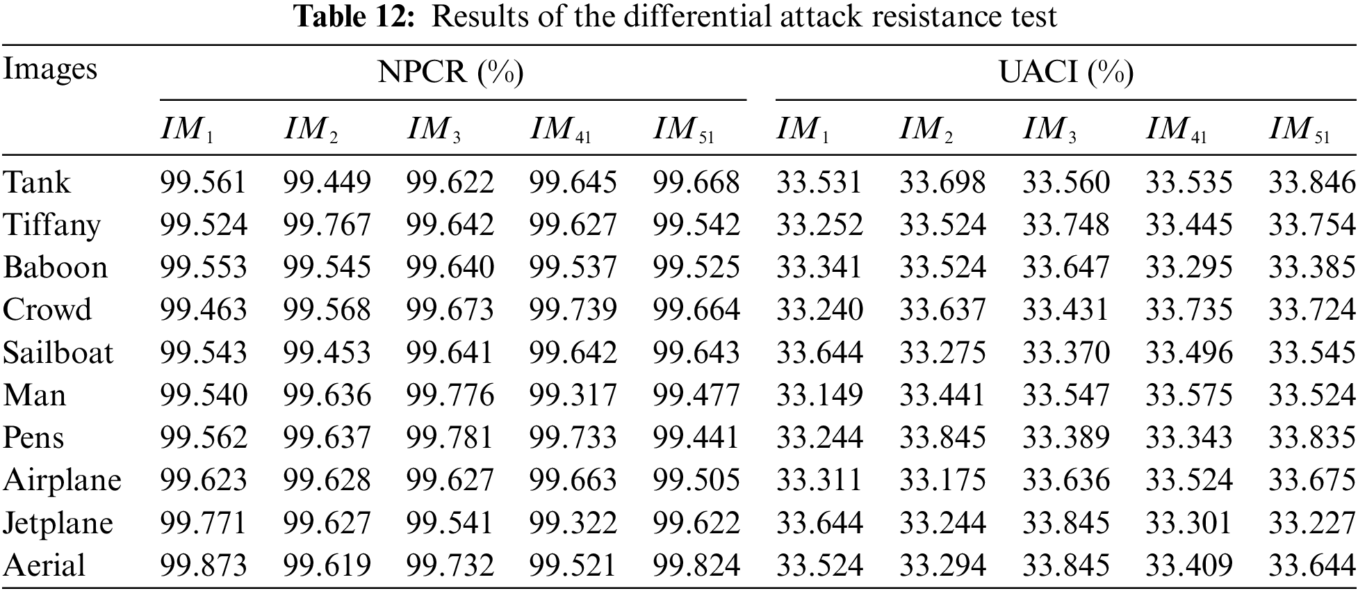
We use the number of pixel change rate (NPCR) and the uniform average change intensity (UACI) [39] to evaluate the resistance of the proposed algorithm against differential attacks. NPCR denotes the rate of pixels at the same location between images that undergo a change. The closer the value is to 100%, the greater the difference between images and the more secure the algorithm is. UACI denotes the average of the pixel differences between two images. An encryption algorithm with good resistance to differential attacks has an optimal NPCR of 99.609% and an optimal UACI of 33.464% [39]. We use this paper’s algorithm based on (4, 5)-threshold and 3-layer access structure to embed three sets of random data into the randomly selected experimental images under the condition of T = 32. We denoted the resulting marked encrypted images as IM1, IM2, and IM3, and assessed their performance using NPCR and UACI metrics. Furthermore, to validate the algorithm’s resistance to chosen-plaintext attacks, we used various key combinations to embed two sets of random data into images where all pixel values are zero. The resulting additional encrypted images are categorized as IM4i and IM5i, as shown in Fig. 14. All these images exhibit a high degree of chaos. We then tested the NPCR and UACI values between these images and the marked encrypted images generated from other images in the database to determine if there were any significant statistical similarities. A high degree of similarity could potentially expose vulnerabilities that attackers might exploit. As presented in Table 12, the NPCR and UACI values for both experiments were found to be approximately 99.609% and 33.464%, respectively. These results suggest that the algorithm is effective at resisting differential attacks and demonstrates a certain degree of robustness against chosen-plaintext attacks. This is due to the fact that the algorithm employs different operations such as coding techniques, scrambling and XOR encryption, which makes the algorithm of this paper a large uncertain system with high security.
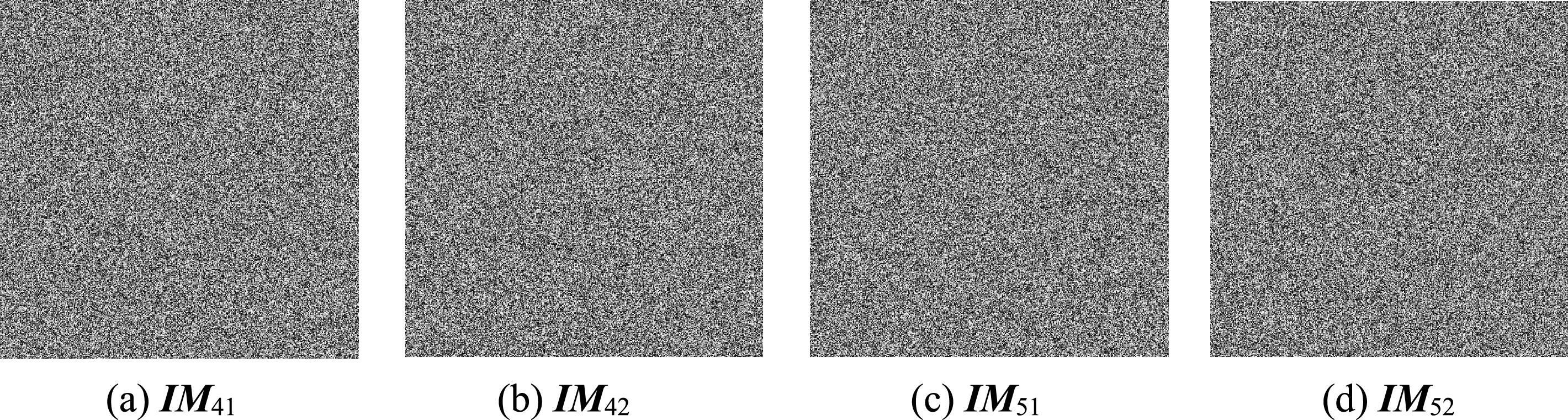
Figure 14: Mark encrypted images generated from the all-zero image
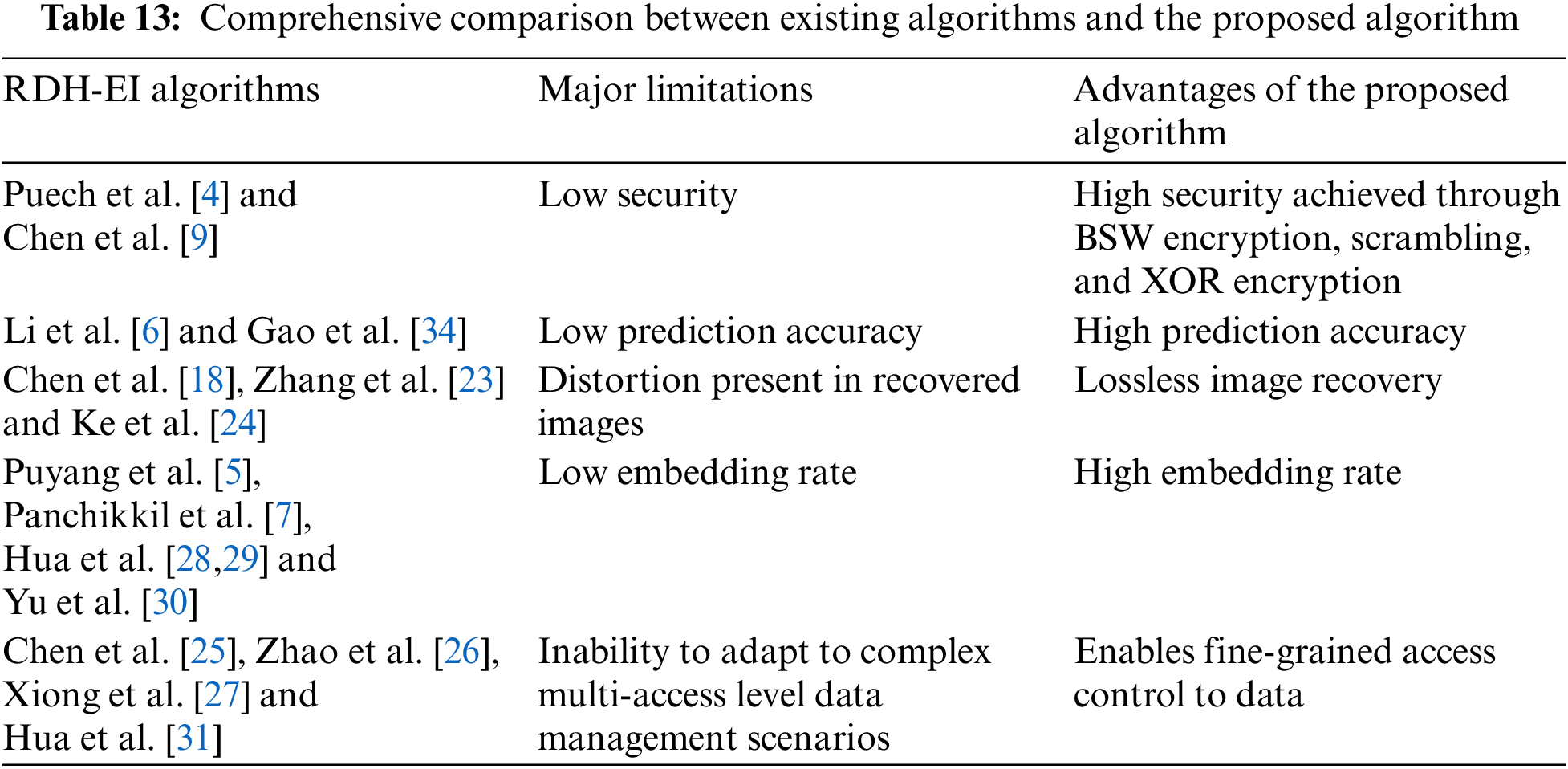
Based on the experimental results, we conducted a comprehensive comparison between existing algorithms and our proposed algorithm, with the findings summarized in Table 13. The proposed algorithm effectively addresses the limitations of the existing algorithms, significantly enhancing the suitability of the RDH-EI algorithm for multi-user cloud services.
To address the issues of constrained embedding capacity and ineffective performance in intricate data retrieval situations encountered by current RDH-EI techniques, we introduce a novel data hiding method based on an innovative prediction method and ciphertext-policy attribute-based encryption, which allows for multi-level embedding of secret data. Our cutting-edge AMED pixel forecasting method demonstrates exceptional accuracy in predictions and is enhanced by Huffman coding for image preprocessing. During image encryption, we embed hierarchical group’s secret data based on user attributes and access levels, resulting in marked encrypted images. Recipients can then extract the corresponding levels of group secret data from these images to recover the original images. The algorithm supports permission granting and joint decryption among users. Experimental results demonstrate that our algorithm achieves full reversibility and significantly improved embedding rates compared to existing approaches. Additionally, by leveraging the threshold properties of attribute encryption, our algorithm shows resilience against data loss and exhibits robust resistance to differential attacks and other statistical attack methods, ensuring a high level of security. Nonetheless, our method exhibits marginally reduced speed compared to current techniques regarding image processing and secret extraction, highlighting the necessity for additional research. Future work will focus on developing RDH-EI algorithms based on color images to enhance both embedding rates and processing speeds, while also meeting the security requirements of multi-user environments in cloud services.
Acknowledgement: The authors would like to convey their deep appreciation to the editors and reviewers for their priceless contributions, as well as to supervisor and family for their constant support throughout the research endeavor.
Funding Statement: This research was funded by the National Natural Science Foundation of China (Grant Numbers 62272478; 62102450; 62102451).
Author Contributions: Conceptualization, Zongbao Jiang; methodology, Zongbao Jiang, Weina Dong; software, Zongbao Jiang; validation, Fuqiang Di; formal analysis, Minqing Zhang; resources, Minqing Zhang, Fuqiang Di; data curation, Weina Dong, Chao Jiang; writing—original draft preparation, Zongbao Jiang, Weina Dong, Chao Jiang; writing—review and editing, Zongbao Jiang; visualization, Weina Dong, Chao Jiang; supervision, Fuqiang Di; project administration, Minqing Zhang. All authors reviewed the results and approved the final version of the manuscript.
Availability of Data and Materials: The data that support the findings of this study are available from the corresponding author, Minqing Zhang, upon reasonable request.
Ethics Approval: Not applicable.
Conflicts of Interest: The authors declare that they have no conflicts of interest to report regarding the present study.
References
1. E. Sisinni, A. Saifullah, S. Han, U. Jennehag, and M. Gidlund, “Industrial internet of things: Challenges, opportunities, and directions,” IEEE Trans. Ind. Inform., vol. 14, no. 11, pp. 4724–4734, Nov. 2018. doi: 10.1109/TII.2018.2852491. [Google Scholar] [CrossRef]
2. M. Ragab, S. Alshehri, H. A. Alhadrami, F. Kateb, E. B. Ashary and S. Abdel-khalek, “Encryption with image steganography based data hiding technique in IIoT environment,” Comput. Mater. Contin., vol. 72, no. 1, pp. 1323–1338, Feb. 2022. doi: 10.32604/cmc.2022.024775. [Google Scholar] [CrossRef]
3. S. Kumar, A. Gupta, and G. S. Walia, “Reversible data hiding: A contemporary survey of state-of-the-art, opportunities and challenges,” Appl. Intell., vol. 52, pp. 7373–7406, Sep. 2022. doi: 10.1007/s10489-021-02789-2. [Google Scholar] [CrossRef]
4. W. Puech, M. Chaumont, and O. Strauss, “A reversible data hiding method for encrypted images,” in Proc. Secur., Forensic., Steganograp., Watermarking Multimed. Contents X, San Jose, CA, USA, Mar. 18, 2008, pp. 534–542. [Google Scholar]
5. Y. Puyang, Z. Yin, and Z. Qian, “Reversible data hiding in encrypted images with two-MSB prediction,” in 2018 IEEE Int. Workshop Inform. Forensic. Secur. (WIFS), Hong Kong, China, Dec. 2018, pp. 1–7. [Google Scholar]
6. S. Li, L. Hu, C. Sun, L. Chi, T. Li and H. Li, “A reversible data hiding algorithm based on prediction error with large amounts of data hiding in spatial domain,” IEEE Access, vol. 8, pp. 214732–214741, Nov. 2020. doi: 10.1109/ACCESS.2020.3040048. [Google Scholar] [CrossRef]
7. S. Panchikkil and V. M. Manikandan, “A prediction error based reversible data hiding scheme in encrypted image using block marking and cover image pre-processing,” Multimed. Tools Appl., vol. 83, no. 2, pp. 4993–5030, May 2023. doi: 10.1007/s11042-023-15319-8. [Google Scholar] [PubMed] [CrossRef]
8. H. T. Wu, Y. M. Cheung, Z. Zhuang, L. Xu, and J. Hu, “Lossless data hiding in encrypted images compatible with homomorphic processing,” IEEE Trans. Cybern., vol. 53, no. 6, pp. 3688–3701, Jun. 2023. doi: 10.1109/TCYB.2022.3163245. [Google Scholar] [PubMed] [CrossRef]
9. Y. C. Chen, T. H. Hung, S. H. Hsieh, and C. W. Shiu, “A new reversible data hiding in encrypted image based on multi-secret sharing and lightweight cryptographic algorithms,” IEEE Trans. Inf. Forensics Secur., vol. 14, no. 12, pp. 3332–3343, May 2019. doi: 10.1109/TIFS.2019.2914557. [Google Scholar] [CrossRef]
10. L. Qu, F. Chen, S. Zhang, and H. He, “Cryptanalysis of reversible data hiding in encrypted images by block permutation and co-modulation,” IEEE Trans. Multimed., vol. 24, pp. 2924–2937, Jun. 2021. doi: 10.1109/TMM.2021.3090588. [Google Scholar] [CrossRef]
11. F. Ren, Y. Hao, K. Pang, and Z. Wu, “Reversible data hiding scheme in encrypted images based on homomorphic encryption and pixel value ordering,” Multimed. Tools Appl., vol. 83, no. 14, pp. 40607–40627, Apr. 2024. doi: 10.1007/s11042-023-17242-4. [Google Scholar] [CrossRef]
12. M. Wang, X. Fu, L. Teng, X. Yan, Z. Xia and P. Liu, “A new 2D-HELS hyperchaotic map and its application on image encryption using RNA operation and dynamic confusion,” Chaos Solit. Fractals, vol. 183, Jun. 2024, Art. no. 114959. doi: 10.1016/j.chaos.2024.114959. [Google Scholar] [CrossRef]
13. S. Gao et al., “Development of a video encryption algorithm for critical areas using 2D extended schaffer function map and neural networks,” Appl. Math. Model., vol. 134, pp. 520–537, Oct. 2024. doi: 10.1016/j.apm.2024.06.016. [Google Scholar] [CrossRef]
14. H. Mansouri, M. A. Tahiri, A. Bencherqui, H. Moustabchir, H. Qjidaa and M. Sayyouri, “Securing color images with an innovative hybrid method combining DNA computing and chaotic systems,” Stat. Optim. Inform. Comput., vol. 12, no. 3, pp. 697–712, Feb. 2024. doi: 10.19139/soic-2310-5070-1952. [Google Scholar] [CrossRef]
15. M. Wang, M. An, X. Zhang, and H. H. Ching Iu, “Two-variable boosting bifurcation in a hyperchaotic map and its hardware implementation,” Nonlinear Dyn., vol. 111, no. 2, pp. 1871–1889, Jan. 2023. doi: 10.1007/s11071-022-07922-5. [Google Scholar] [CrossRef]
16. M. Wang et al., “A novel multistable chaotic system with 2 m-scroll attractor and its application,” Eur. Phys. J. Plus, vol. 139, no. 1, Jan. 2024, Art. no. 64. doi: 10.1140/epjp/s13360-023-04836-y. [Google Scholar] [CrossRef]
17. M. Wang and L. Gu, “Multiple mixed state variable incremental integration for reconstructing extreme multistability in a novel memristive hyperchaotic jerk system with multiple cubic nonlinearity,” Chin. Phys. B, vol. 33, no. 2, Jun. 2023, Art. no. 020504. doi: 10.1088/1674-1056/acddd0. [Google Scholar] [CrossRef]
18. C. C. Chen, C. C. Chang, and K. Chen, “High-capacity reversible data hiding in encrypted image based on Huffman coding and differences of high nibbles of pixels,” J. Vis. Commun. Image Rep., vol. 76, Apr. 2021, Art. no. 103060. doi: 10.1016/j.jvcir.2021.103060. [Google Scholar] [CrossRef]
19. X. Wang, C. C. Chang, and C. C. Lin, “Reversible data hiding in encrypted images with block-based adaptive MSB encoding,” Inf. Sci., vol. 567, pp. 375–394, Aug. 2021. doi: 10.1016/j.ins.2021.02.079. [Google Scholar] [CrossRef]
20. A. Bencherqui et al., “Optimal algorithm for color medical encryption and compression images based on DNA coding and a hyperchaotic system in the moments,” Eng. Sci. Technol., Int. J., vol. 50, Feb. 2024, Art. no. 101612. doi: 10.1016/j.jestch.2023.101612. [Google Scholar] [CrossRef]
21. S. Gao et al., “Temporal action segmentation for video encryption,” Chaos Solit. Fractals, vol. 183, Jun. 2024, Art. no. 114958. doi: 10.1016/j.chaos.2024.114958. [Google Scholar] [CrossRef]
22. X. Wang, L. Y. Li, C. C. Chang, and C. C. Chen, “High-capacity reversible data hiding in encrypted images based on prediction error compression and block selection,” Secur. Commun. Netw., vol. 2021, no. 1, 2021, Art. no. 9606116. doi: 10.1155/2021/9606116. [Google Scholar] [CrossRef]
23. L. Zhang, F. Li, and C. Qin, “Efficient reversible data hiding in encrypted binary image with Huffman encoding and weight prediction,” Multimed. Tools Appl., vol. 81, no. 20, pp. 29347–29365, Apr. 2022. doi: 10.1007/s11042-022-12710-9. [Google Scholar] [CrossRef]
24. Y. Ke, M. Q. Zhang, J. Liu, T. T. Su, and X. Y. Yang, “Fully homomorphic encryption encapsulated difference expansion for reversible data hiding in encrypted domain,” IEEE Trans. Circuits Syst. Video Technol., vol. 30, no. 8, pp. 2353–2365, Aug. 2020. doi: 10.1109/TCSVT.2019.2963393. [Google Scholar] [CrossRef]
25. B. Chen, W. Lu, J. Huang, J. Weng, and Y. Zhou, “Secret sharing based reversible data hiding in encrypted images with multiple data-hiders,” IEEE Trans. Dependable Secur. Comput., vol. 19, no. 2, pp. 978–991, Jul. 2020. doi: 10.1109/TDSC.2020.3011923. [Google Scholar] [CrossRef]
26. X. Zhao, C. Yang, and F. Liu, “On the sharing-based model of steganography,” in Digit. Forensic. Watermarking: 19th Int. Workshop, IWDW 2020, Melbourne, VIC, Australia, Nov. 2020, pp. 94–105. [Google Scholar]
27. L. Xiong, X. Han, C. N. Yang, and X. Zhang, “Reversible data hiding in shared images based on syndrome decoding and homomorphism,” IEEE Trans. Cloud Comput., vol. 11, no. 3, pp. 3085–3098, Mar. 2023. doi: 10.1109/TCC.2023.3259478. [Google Scholar] [CrossRef]
28. Z. Hua, Y. Wang, S. Yi, Y. Zhou, and X. Jia, “Reversible data hiding in encrypted images using cipher-feedback secret sharing,” IEEE Trans. Circ. Syst. Video Technol., vol. 32, no. 8, pp. 4968–4982, Jan. 2022. doi: 10.1109/TCSVT.2022.3140974. [Google Scholar] [CrossRef]
29. Z. Hua et al., “Matrix-based secret sharing for reversible data hiding in encrypted images,” IEEE Trans. Dependable Secur. Comput., vol. 20, no. 5, pp. 3669–3686, Nov. 2022. doi: 10.1109/TDSC.2022.3218570. [Google Scholar] [CrossRef]
30. C. Yu, X. Zhang, C. Qin, and Z. Tang, “Reversible data hiding in encrypted images with secret sharing and hybrid coding,” IEEE Trans. Circ. Syst. Video Technol., vol. 33, no. 11, pp. 6443–6458, Apr. 2023. doi: 10.1109/TCSVT.2023.3270882. [Google Scholar] [CrossRef]
31. Z. Hua, X. Liu, Y. Zheng, S. Yi, and Y. Zhang, “Reversible data hiding over encrypted images via preprocessing-free matrix secret sharing,” IEEE Trans. Circ. Syst. Video Technol., vol. 34, no. 3, pp. 1799–1814, Jul. 2023. doi: 10.1109/TCSVT.2023.3298803. [Google Scholar] [CrossRef]
32. X. Li, W. Zhang, X. Gui, and B. Yang, “Efficient reversible data hiding based on multiple histograms modification,” IEEE Trans. Inf. Forensic. Secur., vol. 10, no. 9, pp. 2016–2027, Jun. 2015. doi: 10.1109/TIFS.2015.2444354. [Google Scholar] [CrossRef]
33. R. Kumar, D. Sharma, A. Dua, and K. H. Jung, “A review of different prediction methods for reversible data hiding,” J. Inf. Secur. Appl., vol. 7878, Nov. 2023, Art. no. 103572. doi: 10.1016/j.jisa.2023.103572. [Google Scholar] [CrossRef]
34. G. Gao, L. Zhang, Y. Lin, S. Tong, and C. Yuan, “High-performance reversible data hiding in encrypted images with adaptive Huffman code,” Digit. Signal Process., vol. 133, Mar. 2023, Art. no. 103870. doi: 10.1016/j.dsp.2022.103870. [Google Scholar] [CrossRef]
35. J. Bethencourt, A. Sahai, and B. Waters, “Ciphertext-policy attribute-based encryption,” in 2007 IEEE Symp. Secur. Priv. (SP’07), Berkeley, CA, USA, Jun. 2007, pp. 321–334. [Google Scholar]
36. P. Bas, T. Filler, and T. Pevný, “Break our steganographic system: The ins and outs of organizing BOSS,” in Information Hiding, Berlin, Heidelberg: Springer, May 2011, pp. 59–70. [Google Scholar]
37. P. Bas and T. Furon, “Image database of BOWS-2,” vol. 20, pp. 2016–2017. Accessed: Jun. 20, 2017. [Online]. Available: https://dde.binghamton.edu/download/ [Google Scholar]
38. G. Schaefer and M. Stich, “UCID: An uncompressed color image database,” in Storage Retr. Methods Appl. Multimed. 2004, San Jose, CA, USA, Dec. 2003, pp. 472–480. [Google Scholar]
39. Y. Wu, J. P. Noonan, and S. Agaian, “NPCR and UACI randomness tests for image encryption,” Cyber J.: Multidiscip. J. Sci. Technol., J. Selected Areas Telecommun. (JSAT), vol. 1, no. 2, pp. 31–38, 2011. [Google Scholar]
Cite This Article
 Copyright © 2024 The Author(s). Published by Tech Science Press.
This work is licensed under a Creative Commons Attribution 4.0 International License , which permits unrestricted use, distribution, and reproduction in any medium, provided the original work is properly cited.
 Downloads
 Citation Tools