 Open Access
ARTICLE
Development of Multi-Agent-Based Indoor 3D Reconstruction
Optical Wireless Lab, Department of Electronic and Computer Engineering, The Hong Kong University of Science and Technology, Hong Kong, China
* Corresponding Author: Chik Patrick Yue. Email:
(This article belongs to the Special Issue: Intelligent Manufacturing, Robotics and Control Engineering)
Computers, Materials & Continua 2024, 81(1), 161-181. https://doi.org/10.32604/cmc.2024.053079
Received 24 April 2024; Accepted 01 August 2024; Issue published 15 October 2024
Abstract
Large-scale indoor 3D reconstruction with multiple robots faces challenges in core enabling technologies. This work contributes to a framework addressing localization, coordination, and vision processing for multi-agent reconstruction. A system architecture fusing visible light positioning, multi-agent path finding via reinforcement learning, and 360° camera techniques for 3D reconstruction is proposed. Our visible light positioning algorithm leverages existing lighting for centimeter-level localization without additional infrastructure. Meanwhile, a decentralized reinforcement learning approach is developed to solve the multi-agent path finding problem, with communications among agents optimized. Our 3D reconstruction pipeline utilizes equirectangular projection from 360° cameras to facilitate depth-independent reconstruction from posed monocular images using neural networks. Experimental validation demonstrates centimeter-level indoor navigation and 3D scene reconstruction capabilities of our framework. The challenges and limitations stemming from the above enabling technologies are discussed at the end of each corresponding section. In summary, this research advances fundamental techniques for multi-robot indoor 3D modeling, contributing to automated, data-driven applications through coordinated robot navigation, perception, and modeling.Keywords
3D reconstruction, the process of generating 3D models from 2D data like images, has emerged as a pivotal technology with broad applications across robotics [1], virtual reality (VR) [2,3], Building Information Modelling (BIM) [4,5], and autonomous navigation [6,7]. This technology enables robots to perceive their surroundings accurately and empowers humans with richer understandings of complex scenes. To address the urgent needs of the developing intelligent construction industry and related applications such as surveillance, robotics, and inspections, core enabling technologies are increasingly important. The level of system intelligence directly impacts task quality and indirectly demonstrates value creation. In construction specifically, traditional human-centered inspection methods using handheld devices inevitably lead to issues such as low efficiency due to time-consuming data collection; high costs from personnel and equipment; low accuracy as relative-only measurements are obtained; uncertain coverage; inability to provide consistent periodic support; and safety concerns when sending humans into dangerous unstable sites. Advancements in technologies like visible light positioning have the potential to help alleviate these challenges by automating inspection and localization functions.
Despite the widespread use of traditional 3D reconstruction methods that often involve complex setups with multiple cameras or specialized hardware [8], the popularity of 360° cameras has significantly increased. 360° cameras have a wider Field-of-View (FOV) than normal perspective cameras, making them suitable for a variety of applications. For instance, 360° cameras are now widely used in the construction industry, as they provide a more efficient means of monitoring the whole construction site.
Due to the calibration difficulties posed by wide FOV cameras, we introduce a solution to address the calibration challenges associated with cameras featuring an ultra-wide FOV. Our approach eliminates the need for sizeable checkerboard calibration patterns, typically required to model lens distortion across a vast angular span. To address the calibration issue, our method projects the distorted Equirectangular Projection (ERP) format of 360° panoramic imagery onto virtual cube faces resembling orthographic perspective views. This projected representation facilitates compatibility with deep learning networks pre-trained on undistorted perspective images, expanding the applicability of low-cost commercial 360° cameras to computer vision tasks involving 3D scene reconstruction. By resolving distortion and aligning the panoramic visual domain with established deep learning models, our technique aims to further the utility of affordable 360° cameras in applications spanning virtual/augmented reality to robotic vision.
In 3D reconstruction, using multiple robots can greatly enhance the accuracy and efficiency of the reconstruction process. This approach is particularly useful for larger and more complex environments. In addition to improving accuracy and efficiency, multi-agent-based reconstruction can also lead to significant time savings. For instance, in construction sites, timely monitoring is crucial for ensuring project progress and safety. Effective monitoring enables better communication and coordination among project stakeholders, minimizing delays and costly problems. With timely monitoring, construction companies can stay on track and deliver projects within the designated timeline. As technology advances, the use of multiple robots in 3D reconstruction is becoming more prevalent and essential.
Orchestrating multiple robots is critical for applications requiring reconstruction at a large scale. To facilitate coordination between multiple mobile robots performing reconstruction tasks, we need to first solve the Multi-Agent Path Finding (MAPF) problem [9]—defining a set of collision-free trajectories within a given environment. While optimally solving MAPF is computationally intractable, several algorithms have been developed to address this challenge. However, they are not effective enough for robots to leverage their combined capabilities for applications involving large-scale indoor 3D reconstruction. Certain methods take a search-based approach, such as utilizing Conflict Based Search (CBS) [10,11], while others reduce the problem formulation into a Boolean Satisfiability Problem (SAT) [12]. However, systems employing these techniques tend to scale with a relatively small number of agents. The computational complexity of directly applying these algorithms poses challenges for coordinating large multi-robot teams performing reconstruction tasks.
To address the scalability limitations, decentralized execution methods leveraging techniques like Imitation Learning (IL) or Reinforcement Learning (RL) have been explored [13–16]. Such decentralized approaches typically frame the MAPF problem as a partially observable Markov game, reducing overhead by enabling agents to make decisions based on local observations rather than requiring complete environmental awareness. RL-oriented techniques incorporate guidance from behavior cloning [13,14] to minimize divergence or utilize heuristics [17] for faster convergence. By distributing computational demands across agents operating with partial information, these decentralized techniques have shown promise for coordinating larger multi-robot teams involved in reconstruction applications.
Researchers have recently explored approaches focused on agent collaboration through communication to further advance multi-agent coordination. Solutions proposed in this domain such as [16–18] emphasize broadcast messaging, whereby signals are transmitted indiscriminately to surrounding bots. While broadcast communication has shown substantial benefits over past work, it inherently produces substantial communication overhead as not all circulated information is equally relevant for decision-making. Additionally, obscuring the signal with extraneous data can confuse agents and potentially degrade learning dynamics over time. As a result, reinforcement learning frameworks aimed at minimizing communication overhead have been investigated [19–23]. Specifically, study [19] presents an approach where robots communicate only with neighbors likely to impact immediate choices, seeking to balance coordination and efficiency in large-scale multi-robot systems.
Precise positional awareness is critical when coordinating the motions of multiple robots, as assumed in the techniques above. However, achieving accurate indoor localization poses major technical challenges. Existing indoor positioning systems relying on technologies like Wi-Fi, Bluetooth, and acoustics often struggle to provide the centimeter-level precision required to enable advanced multi-robot applications. While techniques like Simultaneous Localization and Mapping (SLAM) can achieve higher accuracy, they suffer from complexities such as mapping sharing and scalability. The lack of an indoor equivalent to GPS also presents barriers. Without a solution for ubiquitous, highly accurate indoor navigation, many promising use cases for collaborative robotics and other Internet of Things (IoT) technologies remain out of reach. Developing robust indoor positioning approaches able to meet stringent centimeter-scale requirements represents an important area for continued research, with implications for transforming how both industrial and consumer spaces are utilized.
Over the years, researchers and experts have been exploring various solutions to address the limitations of current existing indoor positioning systems. One such enabling technology that has gained significant attention is Visible Light Communication (VLC). One application of VLC that shows promising performance for providing the high-accuracy positioning requirements of multi-robot systems is visible light positioning (VLP) [24,25]. VLP utilizes VLC between existing Light-Emitting Diode (LED) light fixtures deployed throughout indoor environments and cameras on each robot. When a VLC-enabled LED enters the robot camera’s FOV, its binary light Identifier (ID) code can be decoded by the robot. Each ID holds a precise location in the facility map. The robot then utilizes an image-based positioning algorithm to estimate the camera’s pose to the detected LED, achieving centimeter-level localization accuracy. A key advantage of VLP is that it can achieve this precision indoors without relying on electromagnetic signals, avoiding interference issues. VLP also leverages ubiquitous LED lights already installed for primary lighting purposes. These characteristics make VLP especially suitable for facilitating accurate indoor navigation of fleets of collaborating robots.
To address bottlenecks caused by challenges like high costs and inefficiencies faced across industries, this project proposes an integrated framework (Fig. 1) fusing a mobile robot platform with VLC, MAPF algorithms, and 3D reconstruction techniques. VLP provides centimeter-level indoor localization accuracy, overcoming the limitations of traditional methods. This enhanced precision facilitates more effective MAPF planning, enabling better coordination and collaboration between robots. With an efficient MAPF algorithm, robots can plan paths more efficiently to save time and energy. Additionally, each robot is equipped with a 360° camera, allowing real-time panoramic data collection and 3D reconstruction. This enables various applications, especially in the construction industry, to provide accurate and efficient feedback from its BIM model to users. By integrating centimeter-level localization, collaborative multi-robot planning, and 3D sensing capabilities, the proposed approach presents a promising solution for automation and data collection across industries.
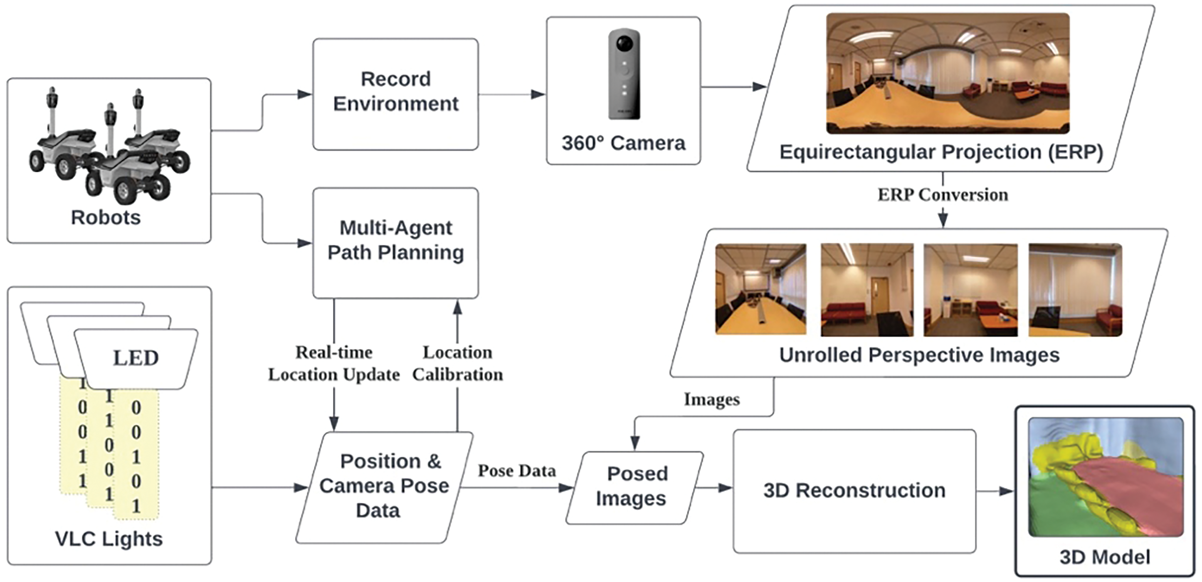
Figure 1: Architecture of the proposed multi-agent-based indoor 3D reconstruction system
VLP holds promise as an indoor localization solution using the ubiquitous LED lighting infrastructure [26]. LEDs enable both VLC and omnipresent IoT applications [27,28]. With the prevalence of LED lighting installations, VLP can capitalize on large-scale deployments [29] of VLC lights for positioning. Meanwhile, the rolling shutter effect of smartphone cameras allows VLP, which is based on Optical Camera Communication (OCC) systems [30], to achieve accuracy within centimeters. By integrating VLP's centimeter-level positioning [31] and global location awareness with onboard robotic sensors such as Inertial Measurement Units (IMU) and odometers, a unified system has the potential to address key challenges in indoor localization in a scalable way without extensive additional infrastructure deployment. The combined capabilities of VLP and robotic localization could realize accurate indoor positioning solutions.
2.1.1 Visible Light Communication
VLP methods can be broadly categorized based on the type of VLC receiver employed: photodiode-based or image sensor-based. While photodiodes have been used in some early VLC systems due to their simplicity, they suffer from issues like excessive sensitivity to varying light intensity and light reflections that degrade positioning accuracy. In contrast, image sensor-based VLC has garnered more widespread adoption in real-world applications due to its better compatibility with common devices like mobile robots and smartphones that already integrate cameras equipped with Complementary Metal-Oxide-Semiconductor (CMOS) image sensors. These techniques leverage the rolling shutter effect from the CMOS image sensors [30] and VLC light modulation, as illustrated in Fig. 2. After that, the binary LED ID can be mapped from the patterns captured by the camera sensor. By extracting the light pattern, we can query the location from the database.
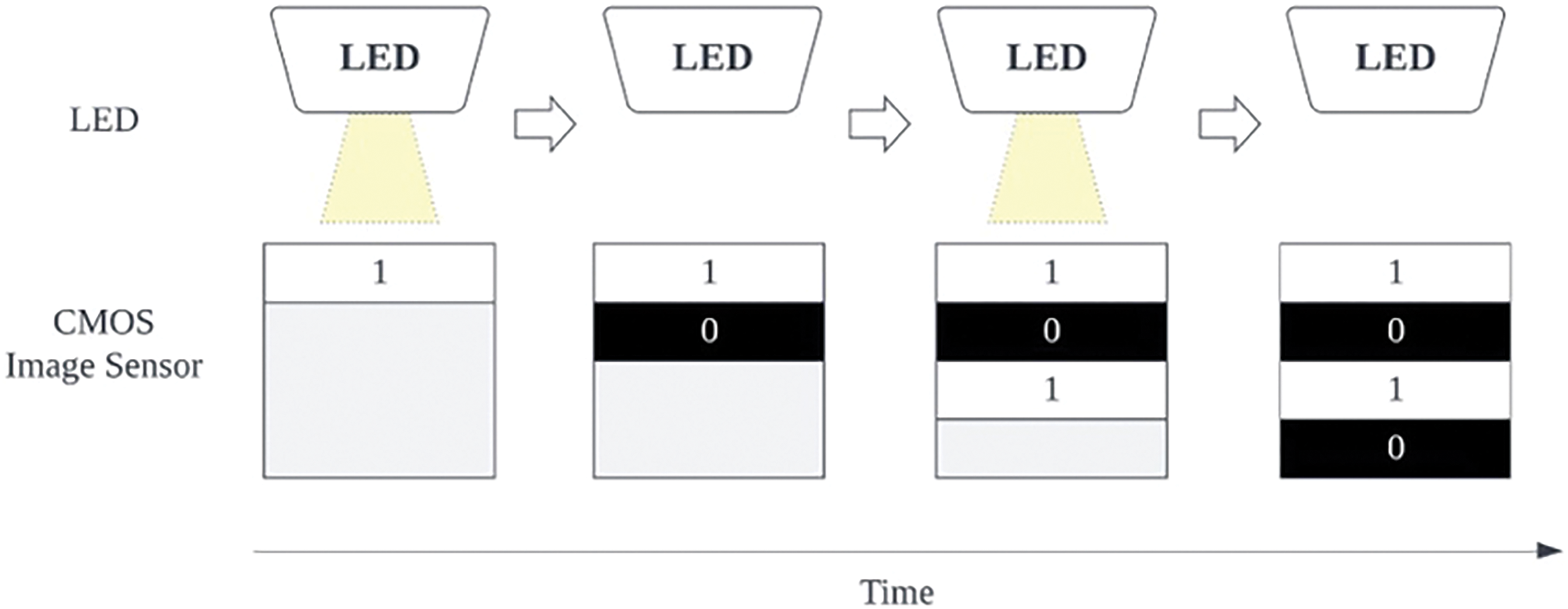
Figure 2: Illustration of the rolling shutter effect on a CMOS image sensor when turning the LED light on and off sequentially
In the VLP system, each LED is programmed with a unique ID encoding important location metadata. To facilitate global localization awareness, the location information stored in the database using this ID includes precise latitude and longitude coordinates as well as additional context like the building, floor, orientation, and physical dimensions. This database is deployed on the cloud to allow easy access via an Application Programming Interface (API), requiring only the LED's ID to retrieve its pre-programmed installation location details. When an LED signal is detected during positioning, the extracted ID is queried against the cloud database to retrieve the LED's unique coordinates [24,29], as depicted in Fig. 3. By directly embedding this contextual data in each LED's ID, the VLC system can seamlessly map detected light signals to precise geospatial coordinates without extra infrastructure or calculations, aided by the globally accessible cloud-hosted location database.
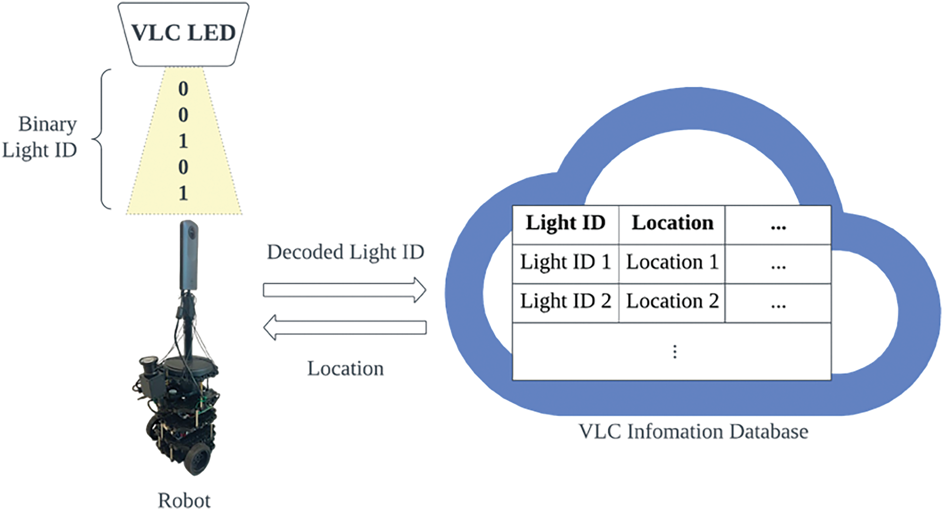
Figure 3: Robot decoding signals from VLC LED and accessing the light location through a database
2.1.2 VLP-Based Robot Navigation
To enable image-based VLC light tracking, a dynamic VLC positioning tracking detection algorithm is deployed to extract the region of interest in the image capturing the VLC LED [25]. Next, we proceed to identify the VLC light ID using an LED recognition algorithm. This algorithm extracts image features and matches them to a pre-established database to identify the position data or coordinates of the LEDs. Using imaging-positioning techniques, the robot's position relative to the LEDs in the localization area is determined, thus achieving accurate indoor positioning. The image processing tasks, including LED feature tracking, light ID extraction, and coordinate calculation, are carried out remotely by a server connected to the same local network as the robot.
In the above framework, we propose the integration of a 3D positioning algorithm [29] to further enhance the indoor positioning precision on top of the LED’s location queried from the database. Leveraging the pinhole camera model, the algorithm utilizes a camera mounted on the robot to capture images of ceiling-mounted VLC lights. The lights’ projections in the image are used to determine the relative position of the robot to the VLC lights [28], as shown in Fig. 4. To transform real-world 3D points onto a 2D image plane, we first define a camera extrinsic matrix. The extrinsic matrix models the spatial relationship between the camera's coordinate system and the world coordinate system, which specifies the camera's position and orientation in world space. Specifically, the extrinsic matrix is defined by the following equation, in which R and T represent the rotation and translation relating the camera to the world frame:
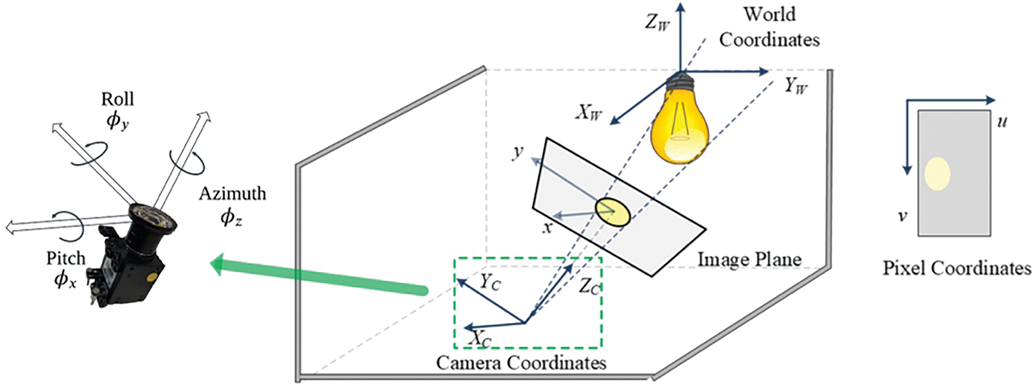
Figure 4: Illustration of the spatial relationship between light, onboard camera, and image plane [29]
Notice that the translation matrix T is the coordinates of the camera w.r.t. the VLC light. In the scenario where the camera is close to the ground,
In addition, the camera intrinsic matrix is also defined as
where
The calculation of the LED position, based on the pinhole camera model with scale factor
The 3D coordinates of the light w.r.t. world coordinate, as denoted by
Based on our VLC setup and VLP algorithm, we built an experimental testbed [25] to evaluate the robot’s positioning. A ceiling-facing camera on a robot captures images of VLC-enabled LEDs, from which our ID recognition algorithm determines the corresponding light IDs and queries the LEDs’ position from the database. After that, our positioning algorithm based on the pinhole camera model calculates the robot's real-time position with respect to the LED, as the final position. As demonstrated in Fig. 5, we tested our VLP algorithm for single-robot navigation using the Turtlebot3 robotic platform equipped with an onboard camera for capturing VLC signals. The Turtlebot3 robot runs on Ubuntu 16.04 MATE, and a server (Lenovo Thinkpad, Core i7, 16 GB RAM) that processes the image data runs on Ubuntu 16.04 and ROS Kinetic. We successfully navigated the robot and tracked its trajectory in an RViz-visualized demo, validating our VLP approach for robot localization.
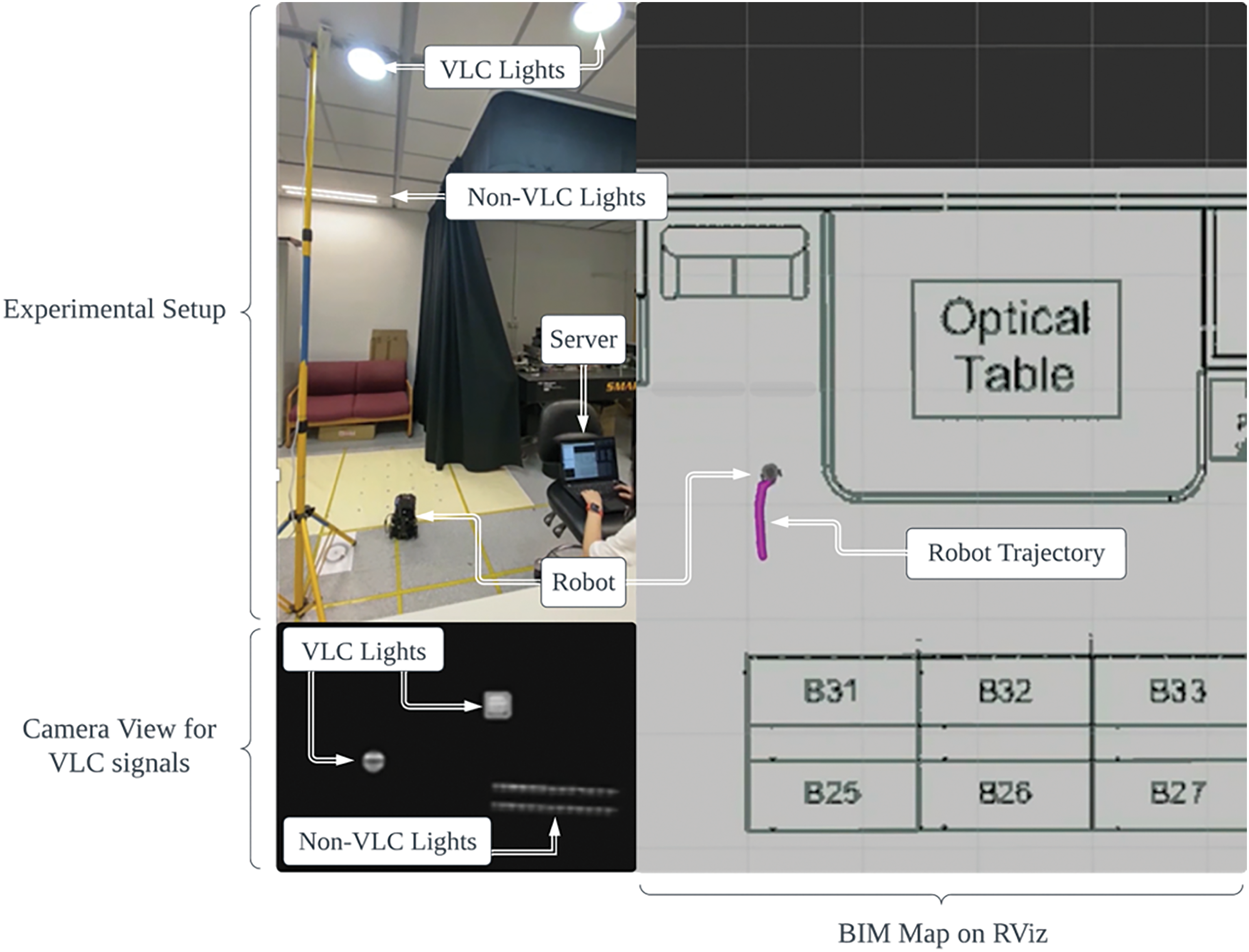
Figure 5: Demonstration setup of high-precision positioning system based on VLC smart lighting [25]. The robot's trajectory is represented by a trail of purple dots, with the robot model depicted in gray, and real-time captured VLC signals shown at the bottom left
2.1.3 Challenges and Limitations
Although VLC and VLP enable many promising applications, realizing their full potential remains challenging due to considerable technical limitations. For instance, light fixture costs pose a major hurdle to widespread VLP adoption. While LED lighting is common, upgrading existing installations with VLC modulators requires new hardware. Retrofitting an entire building or campus would involve significant expenditure to procure hundreds of LEDs. Their installation also demands time and labor to physically upgrade each unit. Such infrastructure investments could easily run into the tens of thousands or more for large spaces. The financial barriers are prohibitive compared to cheaper solutions such as WiFi, that reuse access points. To become economically competitive, VLP requires a substantial cost reduction, potentially achievable through emerging alternatives like less-expensive LED drivers.
Line-of-sight transmission grants benefits but introduces vulnerabilities. Line-of-sight links avoid radio frequency interference, so VLC signals propagate predictably within rooms. However, this sensitivity also creates vulnerabilities. Even slight obstructions may cause brief but critical losses of positioning data. Positioning disruptions could occur when people walk between robots and VLC lights, obstructing the line-of-sight communication paths. Furthermore, dynamic indoor environments pose challenges to maintaining clear lines as occupants and objects move independently over time. Addressing these unpredictable disruptions will require complex navigation algorithms and continuous positioning fixes.
The tradeoff between VLC signal length (using longer binary codes) and computation efficiency also introduces constraints. The number of supported VLC light IDs is represented as
Relying on remote databases introduces reliability issues. Cloud infrastructure introduces risks if the network experiences intermittent connectivity or high latency. Location look-ups with long delays would degrade the usability of VLC as a real-time positioning system. Positioning would come to a complete halt during outages or when IDs cannot be resolved, resuming only after connectivity is restored. In mission-critical applications like search and rescue operations, such dependencies could have catastrophic consequences during connectivity failures. Improving robustness to network conditions will be vital to ensure consistent, dependable localization services.
Orchestrating large robot fleets for 3D reconstruction requires solving the MAPF problem to define collision-free trajectories. While existing MAPF algorithms [10–12] have been developed to address this challenge, they do not scale effectively to large teams due to the exponential increase in planning complexity. To mitigate this, our approach utilizes a decentralized RL framework in which each robot makes localized decisions based on partial observations. Furthermore, our model incorporates inter-robot communication to facilitate collaboration among robots with limited information access. With decentralized execution and communication, robots can navigate themselves to collaboratively accomplish reconstruction tasks, while avoiding exponential planning complexity that hinders scaling to large fleets.
2.2.1 Multi-Agent Path Finding via Reinforcement Learning
Drawing inspiration from the RL model architectures presented in [17,19], which [17] enables communications among agents and [19] utilizes the selective communication mechanism inspired by Individually Inferred Communication [20]. The decentralized multi-agent RL model contains four main components: an observation encoder, a decision causal unit, a communication block, and a Dueling Deep Q Network (DQN) [32].
Each agent takes a 6-channel observation tensor of size
The decision causal unit determines whether communication should be triggered between agent
In other words, the communication scope selectively targets neighbors that potentially impact agent i's decision, based on an analysis of how decisions change with and without the presence of each neighbor.
Communication between neighbors occurs in a request-reply fashion for better efficiency. Given a communication scope
Within the communication block, the message
where
The output
A Dueling DQN model, which leverages advantage functions, is used to estimate the Q-value based on the outputs from the communication block. We first calculate the advantage mean
where N is the size of the action space. Specifically, we subtract the advantage value from the advantage mean to stabilize training, and add the state value as the final adjustment as described in
After we get the Q-values from the DQN model, a multi-step Temporal Difference error is calculated to update the model parameters by minimizing the mean squared error between the total discounted rewards and the predicted Q-values, as shown in
The total discounted rewards are defined as
2.2.2 Optimizing Communication in MAPF via RL
As described above, our multi-agent RL approach utilizes a decentralized model to facilitate robot coordination. A crucial element of this model is the communication block, which enables information sharing between agents based on their defined communication scopes. These scopes are primarily determined by the agents' FOVs, which correspond to their perception range, typically provided by Light Detection and Ranging (LiDAR) or ultrasonic sensors. Optimizing the agents' FOVs becomes especially important in this context because it strikes a balance between minimizing the computational burden of coordinating larger communication scopes and maximizing performance.
Consequently, investigating the influence of FOV settings on both performance and computational requirements is crucial for designing scalable multi-agent systems. Many state-of-the-art works that applied RL to MAPF, including [17,19], have not explored varying FOV sizes, opting instead for a default FOV size of 9 × 9. Therefore, a 9 × 9 FOV configuration serves as our initial baseline for evaluation and analysis. We assessed the impacts of different FOV settings through three key performance metrics: success rate, average steps, and number of communications. Success rate refers to the percentage of agents arriving at their designated destination within the allotted maximum number of steps. Average steps denote the mean number of maneuvers required across all agents to complete a MAPF scenario. Agents were permitted a maximum of 256 steps per task. Finally, the number of communications represents the total quantity of request-reply exchanges generated during each MAPF solution. We evaluated the model using five different FOVs, i.e., {3 × 3, 5 × 5, 7 × 7, 9 × 9, and 11 × 11} on 40 × 40 and 80 × 80 map sizes. The model was trained on HKUST HPC3 (2 RTX 6000 GPUs and 6 Intel Xeon Gold 6230 CPUs) using a curriculum training approach.
Fig. 6 shows success rates, average steps, and number of communications across different FOVs in an 80 × 80 map. On average, the 7 × 7 FOV outperformed the baseline 9 × 9 FOV with 4.2% higher success rate and 3.0% fewer average steps. Although receiving the least information, the 3 × 3 FOV demonstrated relatively small sacrifices, with success rates being 5.85% and 1.65% lower than 7×7 and 9×9, respectively. For average steps, 3 × 3 exhibited 4.2% and 1.0% more steps than 7 × 7 and 9 × 9.
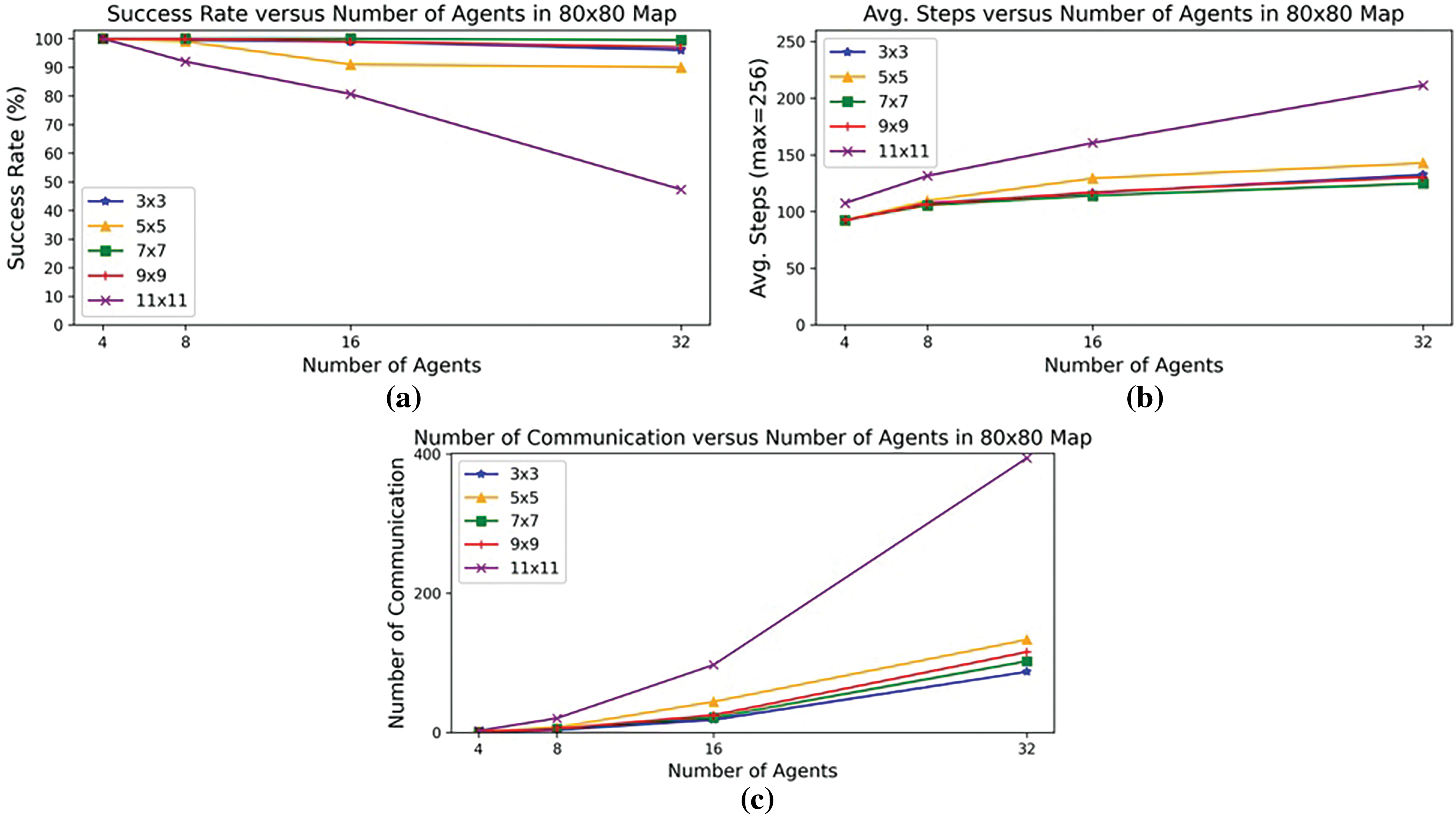
Figure 6: Performance of different FOVs in (a) success rate, (b) average steps, and (c) number of communications [33]
Despite receiving the least amount of surrounding information, the 3 × 3 FOV demonstrated a significant reduction in communication overhead. Specifically, it achieved a 28.9% reduction compared to the 9 × 9 baseline and a 24.4% reduction compared to the highest-performing 7 × 7 FOV. The 3 × 3 FOV’s combination of minimal communication yet small performance impacts make it preferable when bandwidth is constrained, such as for deploying many networked robots with limited communication devices.
2.2.3 Challenges and Limitations
A key challenges lies in the development of algorithms capable of handling dynamic environments where obstacles or agents may move unpredictably over time. Most MAPF formulations assume a static map, but real-world scenarios are often more dynamic. Algorithms need to efficiently re-plan solutions in response to changes while minimizing disruption. This is particularly difficult with large teams where minor perturbations could cascade effects across agents.
Decentralized execution poses challenges in maintaining the coherence of the overall plan. When agents operate solely on local information, their behaviors might diverge over time without proper coordination. Effectively achieving global convergence under such conditions of partial observability remains an open research problem. This lack of global awareness significantly complicates the training phase. Additionally, integrating communication effectively is non-trivial, as excessive messaging also degrades performance. The relationship between communication and emergent coordination requires deeper study, and algorithms that promote further coordination, such as [34], should be considered.
Although discretizing space into a grid offers computational advantages for path finding algorithms, it cannot accurately capture environments with obstacles smaller than the grid’s resolution. However, discretized representations can still be useful when applied as a global planning approach to provide an initial coarse trajectory. For global planning over a large area, using a discretized grid maintains efficiency even with a lower resolution that loses some detail. This allows the development of a high-level collision-free route for guidance. However, once within proximity, a local planner is needed to refine the trajectory. The local planner should work with a smaller-scale, higher-resolution continuous or grid map centered around the robot. This enables finer-grained navigation that considers smaller obstacles not represented in the global map. By using discrete grids for the computationally efficient global planning element, coupled with a local planner for finer maneuvering, both generality and efficiency can be balanced. This two-level approach distributes computations between planners and presents a promising direction worth further exploration to integrate discrete and continuous representations.
Addressing these challenges requires developing more sophisticated MAPF algorithms that can effectively handle dynamic environments, maintain coherence in decentralized execution, and integrate communication selectively without compromising performance. Potential solutions include incorporating dynamic obstacle avoidance techniques into the RL framework, exploring distributed consensus algorithms to enhance coordination among agents, and developing adaptive communication protocols based on environmental complexity and task requirements. Further research is needed to explore these avenues and develop robust and scalable solutions for real-world multi-robot 3D reconstruction applications.
2.3.1 360° Camera Image Acquisition
The real-time capture and transfer of images directly from a 360° camera to a ROS system presents challenges due to the significant time needed to access and transfer the camera's high-resolution images. While 360° cameras can output a live video stream in real-time, this stream is often compressed, generally in the H.264 format, due to the high resolution of omnidirectional images. To utilize the video stream as input to an image capture system on the ROS platform, the compressed stream must first be decompressed and converted to a standard image format that is compatible with image processing pipelines, such as bitmap or JPEG. Specifically, 360° camera video streams are typically compressed to address the large data sizes of high-resolution spherical imagery, but this compression prevents direct usage of the stream within image processing workflows. Therefore, decompression and format conversion of the compressed video to a suitable image format is required to enable real-time image capture and processing on ROS.
To overcome this challenge, we developed a video processing pipeline that utilizes the live compressed video stream directly from the 360° camera. Our implementation employs a popular 360° camera model, the Ricoh Theta V, which outputs an H.264 compressed video stream through its Linux driver. We then use Gstreamer to decompress the video, converting each frame to a JPEG image, as shown in Fig. 7. The process is performed on a ROS server (Lenovo ThinkPad, Core i7, 16 GB RAM) using a pipeline that includes H.264 video decoding. The pipeline is managed through a queuing system to accommodate variations in block processing time. The resulting images are then outputted on a standard ROS image topic. We tested this approach using standard 4 and 2 K video resolutions from the camera, achieving measurable frame rates for the real-time applications on the ROS platform. The result is shown in Table 1.
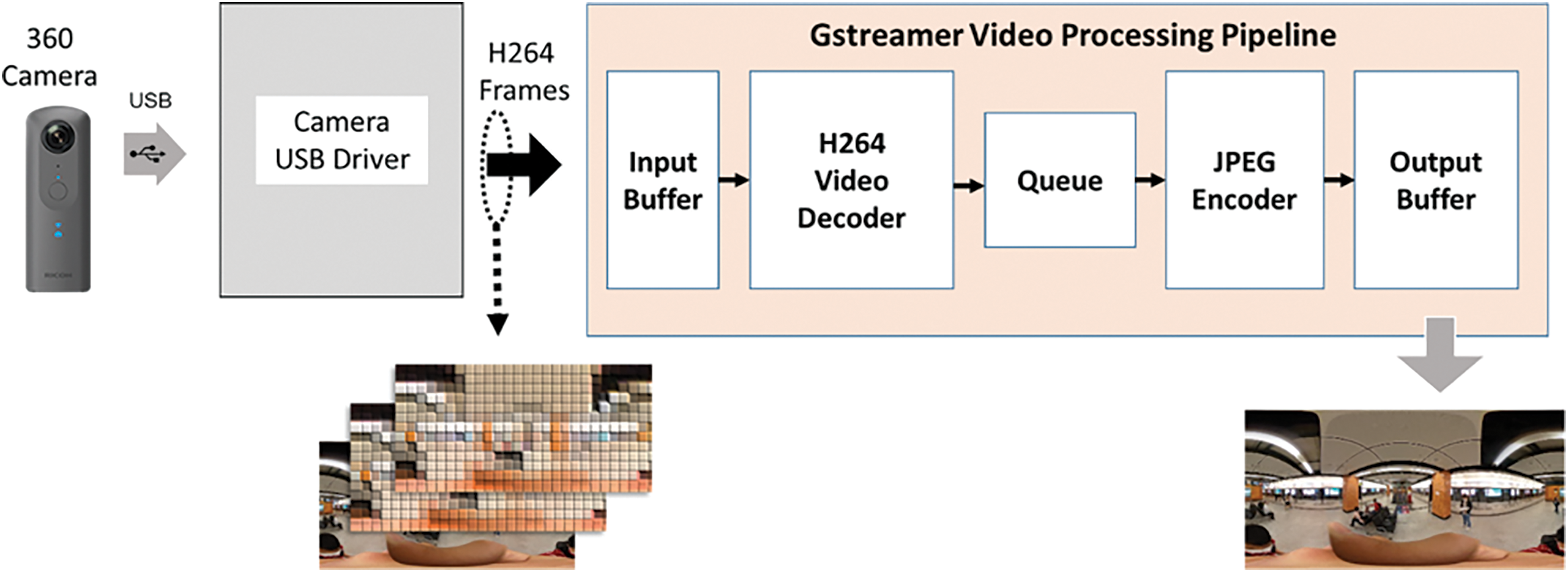
Figure 7: 360° camera video processing pipeline on ROS platform

2.3.2 Conversion for Equirectangular Projection
The output images from the video processing pipeline (Fig. 8) are stored in ERP format, which is highly distorted with increased distortion towards the top and bottom halves. Accurately determining relative sizes and projections using these images within a neural network-based 3D reconstruction framework requires intrinsic camera calibration to extract parameters. However, calibrating 360° cameras is challenging as their wide FOV necessitates an impractically large calibration checkerboard pattern for indoor use. Moreover, ERP images are generally unsuitable for deep learning models which are trained on regular perspective images with low distortion, posing limitations for standard pipelines.

Figure 8: Implementation of ERP conversion and calibration in ROS
To address the distortions inherent in the ERP format, our proposed solution involves converting the panoramic ERP image into four perspective views [35]: front, right, back, and left. The visualization of this process is presented at Fig. 9. Typically, 360° cameras utilize two fish-eye lenses to capture views that are stitched together. For our experiment, we have chosen to crop the top and bottom views due to limitations in accurately merging them. As shown in Fig. 9, the conversion maps the spherical pixel coordinates from the ERP onto four rectangular tangent planes, transforming the representation into more manageable cube-map style outputs, resembling the perspective of four virtual cameras positioned in different orientations around the scene. Similarly, we tested the conversion processing time using 4 K and 2 K video resolutions as presented in Table 2.
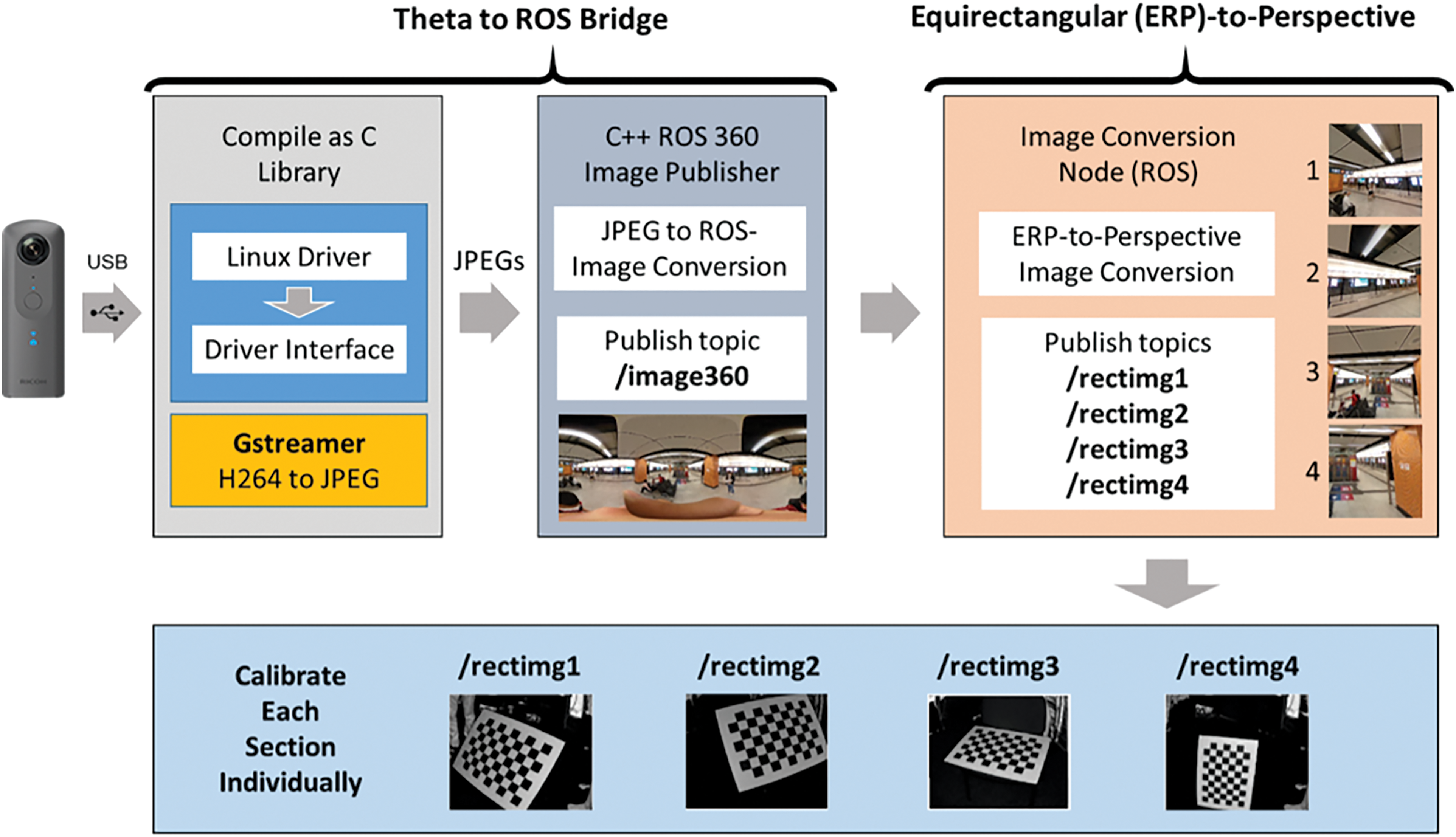
Figure 9: Processing pipeline overview for converting ERP into perspective images and deriving their corresponding poses [35]. The top graph shows a spherical-to-rectangular pixel mapping for an ERP

While perspective images contain less distortion than the original ERP format, even minor warping can influence 3D reconstruction accuracy. In our ROS platform implementation (Fig. 9), a dedicated node performs the ERP-to-perspective conversion and publishes the resulting perspective images as ROS topics. We then calibrate each perspective view individually to account for any remaining distortions. By decomposing the distorted spherical panorama into conventional perspective cube-map views, our approach aims to address the limitations of working directly with the ERP projection for subsequent processing steps like visualization and 3D reconstruction.
2.3.3 Pose Estimation of Cube-Map Views
The camera's pose for perspective images can be determined by applying a rigid body transformation based on the robot's location, which is calculated using a fusion of sensors such as IMU and LiDAR. This transformation utilizes four distinct sets of rotation vectors, one for each horizontal view (front, right, back, left) of the cube-map. As depicted in Fig. 10, the poses for the four views share the same x and y coordinates but exhibit 90° differences in yaw angle. To validate these poses, we collected a dataset in a conference room by sending the robot on a predetermined trajectory to capture posed images at 1-s intervals. Fig. 10 displays the 3D view of camera poses at various locations along the robot’s trajectory.
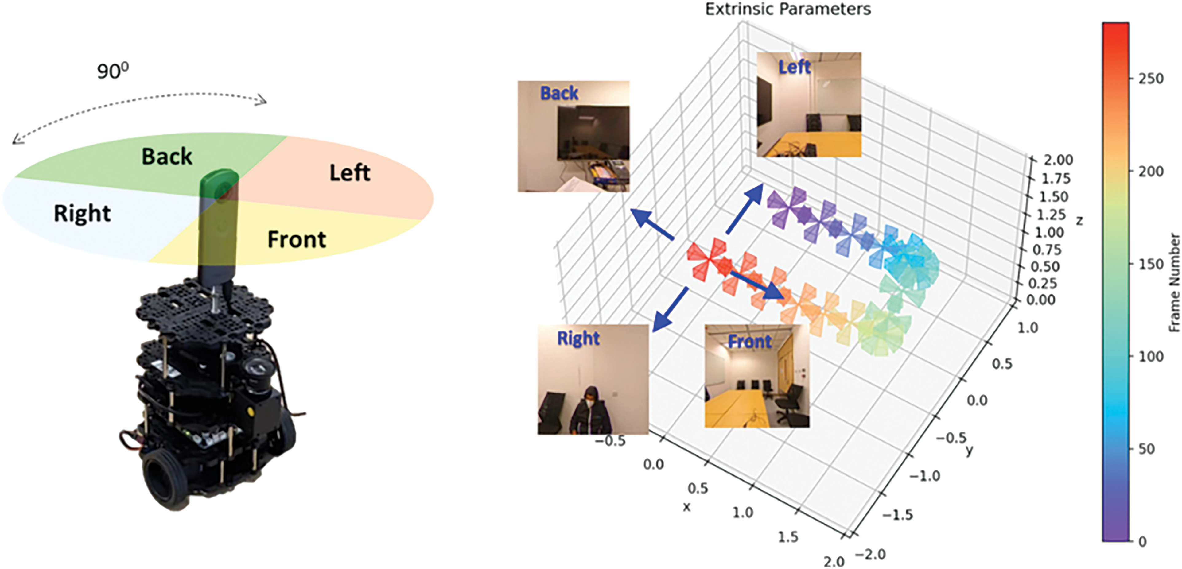
Figure 10: Estimating camera poses for cube-map using XYZ transformations and a 90° phase shift
2.3.4 3D Reconstruction Results
To facilitate 3D reconstruction from ERP imagery for applications like VR and BIM using solely visual perception techniques, our pipeline first converts the ERP format into a representation suitable for depth-independent 3D reconstruction. We leverage ERP-to-perspective image conversion to generate conventional perspective images paired with the corresponding camera poses. By combining the extracted poses with the aligned perspective images, we then feed these posed images into our 3D reconstruction pipeline. While depth sensing is commonly used to aid 3D modeling, fulfilling our objective of depth-independent reconstruction requires a different approach. We drew upon the work of Atlas [36] a neural network architecture that enables end-to-end regression of 3D structures directly from posed monocular imagery, without relying on depth cues.
Specifically, Atlas first applies a 2D convolutional neural network to individually encode visual features from each input image. Leveraging the known intrinsic and extrinsic camera parameters, it then back-projects these 2D features into a joint 3D voxel representation. These accumulated voxels undergo further 3D CNN processing to predict a 3D mesh representing the environment. Other than the 3D mesh itself, the model is also capable of inferring the semantic labeling, which is the assignment of class labels to the mesh.
To evaluate the performance of the entire pipeline, we compared the final 3D model with a ground truth point cloud obtained from a LiDAR sensor (Fig. 11). Notice that semantic labels are not present in the ground truth due to the nature of LiDAR data. Our full experiment was conducted within a 30

Figure 11: Qualitative comparison between ground truth and 3D reconstruction result [35]
2.3.5 Challenges and Limitations
A primary challenge we encountered stemmed from the reliance on accurate robot pose estimation for determining camera positions and orientations. However, pose sensing with IMU, odometry, and LiDAR each have limitations that can introduce errors. However, IMUs are prone to drift over time, odometry can accumulate errors on slippery or uneven surfaces, and LiDAR measurements might suffer from noise or offer incomplete views due to occlusions. When these sources are fused for robot pose, even small uncertainties in the estimated trajectory get magnified in their impact. This impact is further exacerbated when utilizing lower-cost sensors and fusion systems, which tend to be less precise. Inaccurate camera poses directly affect the ability of 3D reconstruction models, such as Atlas, to effectively utilize pose information during the reconstruction process. Structures may appear distorted or incomplete in the final model if image locations are geometrically misaligned. While sensor fusion helps mitigate individual limitations, further advancements are still needed to achieve robust, drift-free localization in real-world environments. More accurate and reliable robot pose sensing will be critical to overcome this challenge and fully realize the quality of reconstruction possible through our approach.
Although 360° cameras offer the advantage of a wide FOV, direct utilization of the raw ERP format for 3D reconstruction presents challenges due to its inherent distortions. Our proposed ERP-to-perspective conversion aims to address these issues by transforming the input into a more manageable cube-map representation. However, this additional processing step inherently discards some information from the original panoramic capture and introduces computational overhead compared to working directly with ERP images. Ideally, algorithms and models could be developed to leverage the full 360° information contained within ERP formats while also addressing the issues of distortion. In the future, it may be possible to build upon these techniques to design new pose estimation and reconstruction systems optimized for ERP, eliminating the need for our conversion methodology. Doing so could improve efficiency and avoid any loss of visual data associated with converting to perspective views. However, for applications requiring perspective outputs, our approach offers a practical solution given the current technical limitations of operating directly on ERP distortions for many vision tasks.
While Atlas provides decent 3D reconstructions from posed images, it currently relies on offline processing which takes time to generate the results. This makes it unsuitable for applications requiring real-time or interactive reconstruction, such as a real-time perception system for robots. Recent works like CDRNet [37] have demonstrated the ability to perform 3D reconstruction in a real-time fashion by inferring 3D mesh on the fly. Transitioning to a real-time 3D reconstruction pipeline has the potential to significantly expand the range of applications for our 360° vision system. It would open up possibilities in areas like dynamic scene understanding, and robotic perception that require continual, low-latency geometric insights rather than offline processing of pre-recorded data.
In this work, we proposed an integrated framework for multi-robot indoor 3D reconstruction leveraging VLP, MAPF, and 360° vision techniques. By providing centimeter-level localization accuracy, VLP overcomes the limitations of existing indoor localization methods. This precision enables more effective MAPF planning and robot coordination. Our decentralized RL-based MAPF approach allows localized decisions based on partial observation and facilitates coordinated navigation in large environments. Equipping robots with 360° cameras allows capturing panoramic imagery for subsequent depth-independent 3D reconstruction. By addressing distortions through ERP-to-perspective conversion, our approach enables reconstruction from posed monocular images with deep learning techniques. Experimental validation demonstrated centimeter-level navigation and 3D modeling capabilities in real test environments. While challenges remain around sensor fusion uncertainties and infrastructure costs, this work advances core enabling technologies with implications for automating data-driven applications across industries. To support a more complete framework, future work will explore real-time reconstruction and adaptation to dynamic conditions. Overall, the presented multi-modal framework represents a promising solution for collaborative robotics and large-scale indoor reconstruction tasks.
Acknowledgement: We would like to express our appreciation to the participants who generously volunteered their time and expertise for this study.
Funding Statement: This work is in part supported by Bright Dream Robotics and the HKUST-BDR Joint Research Institute Funding Scheme under Project HBJRI-FTP-005 (Automated 3D Reconstruction using Robot-mounted 360-Degree Camera with Visible Light Positioning Technology for Building Information Modelling Applications, OKT22EG06).
Author Contributions: Methodology, conceptualization, experiment, writing, review: Hoi Chuen Cheng, Frederick Ziyang Hong, Babar Hussain, Yiru Wang, Chik Patrick Yue; Supervision: Chik Patrick Yue. All authors reviewed the results and approved the final version of the manuscript.
Availability of Data and Materials: Not applicable.
Ethics Approval: Not applicable.
Conflicts of Interest: The authors declare that they have no conflicts of interest to report regarding the present study.
References
1. Y. Tao, M. Popović, Y. Wang, S. T. Digumarti, N. Chebrolu and M. Fallon, “3D lidar reconstruction with probabilistic depth completion for robotic navigation,” in IEEE/RSJ Int. Conf. on Intell. Robots and Syst. (IROS), Kyoto, Japan, 2022, pp. 5339–5346. [Google Scholar]
2. F. Gherardini, M. Santachiara, and F. Leali, “3D virtual reconstruction and augmented reality visualization of damaged stone sculptures,” IOP Conf. Ser.: Mater. Sci. and Eng., vol. 364, 2018, Art. no. 012018. [Google Scholar]
3. S. G. Izard, R. S. Torres, O. A. Plaza, J. A. J. Mendez, and F. J. García-Peñalvo, “Nextmed: Automatic imaging segmentation, 3D reconstruction, and 3D model visualization platform using augmented and virtual reality,” Sensors, vol. 20, no. 10, 2020, Art. no. 2962. [Google Scholar]
4. B. Wang, Q. Wang, J. C. Cheng, C. Song, and C. Yin, “Vision-assisted BIM reconstruction from 3D LiDAR point clouds for MEP scenes,” Automat. in Constr., vol. 133, 2022, Art. no. 103997. [Google Scholar]
5. J. Mahmud, T. Price, A. Bapat, and J. -M. Frahm, “Boundary-aware 3D building reconstruction from a single overhead image,” in Proc. of the IEEE/CVF Conf. on Comput. Vis. and Pattern Recognit. (CVPR), Seattle, WA, USA, 2020, pp. 441–451. [Google Scholar]
6. Y. Huang, W. Zheng, Y. Zhang, J. Zhou, and J. Lu, “Tri-perspective view for vision-based 3D semantic occupancy prediction,” in Proc. of the IEEE/CVF Conf. on Comput. Vis. and Pattern Recognit. (CVPR), Vancouver, BC, Canada, Jun. 18–22, 2023, pp. 9223–9232. [Google Scholar]
7. X. Yan et al., “Sparse single sweep LiDAR point cloud segmentation via learning contextual shape priors from scene completion,” Proc. of the AAAI Conf. on Artif. Intell. (AAAI), vol. 35, no. 4, pp. 3101–3109, 2021. doi: 10.1609/aaai.v35i4.16419. [Google Scholar] [CrossRef]
8. R. Ren, H. Fu, H. Xue, Z. Sun, K. Ding and P. Wang, “Towards a fully automated 3D reconstruction system based on LiDAR and GNSS in challenging scenarios,” Rem. Sens., vol. 13, no. 10, 2021, Art. no. 1981. doi: 10.3390/rs13101981. [Google Scholar] [CrossRef]
9. R. Stern et al., “Multi-agent pathfinding: Definitions, variants, and benchmarks,” in Symp. on Combinatorial Search, Napa, CA, USA, 2019, pp. 151–159. [Google Scholar]
10. G. Sharon, R. Stern, A. Felner, and N. R. Sturtevant, “Conflict-based search for optimal multi-agent pathfinding,” Artif. Intell., vol. 219, pp. 40–66, 2015. doi: 10.1016/j.artint.2014.11.006. [Google Scholar] [CrossRef]
11. V. Rybář and P. Surynek, “Highways in warehouse multi-agent path finding: a case study,” Int. Conf. on Agents and Artif. Intell. (ICAART), vol. 1, pp. 274–281, 2022. doi: 10.5220/0010845200003116. [Google Scholar] [CrossRef]
12. P. Surynek, A. Felner, R. Stern, and E. Boyarski, “Efficient sat approach to multi-agent path finding under the sum of costs objective,” in Proc. Eur. Conf. on Artif. Intell. (ECAI), The Hague, Holland, 2016, pp. 810–818. [Google Scholar]
13. G. Sartoretti et al., “PRIMAL: Pathfinding via reinforcement and imitation multi-agent learning,” IEEE Robot. Automat. Lett. (RA-L), vol. 4, no. 3, pp. 2378–2385, 2019. doi: 10.1109/LRA.2019.2903261. [Google Scholar] [CrossRef]
14. M. Damani, Z. Luo, E. Wenzel, and G. Sartoretti1, “PRIMAL2: Pathfinding via reinforcement and imitation multi-agent learning—Lifelong,” IEEE Robot. Automat. Lett., vol. 6, no. 2, pp. 2666–2673, 2021. doi: 10.1109/LRA.2021.3062803. [Google Scholar] [CrossRef]
15. Z. Liu, B. Chen, H. Zhou, G. Koushik, M. Hebert and D. Zhao, “MAPPER: Multi-agent path planning with evolutionary reinforcement learning in mixed dynamic environments,” in IEEE/RSJ Int. Conf. on Intell. Robots and Syst. (IROS), Las Vegas, NV, USA, 2020, pp. 11748–11754. [Google Scholar]
16. Q. Li, F. Gama, A. Ribeiro, and A. Prorok, “Graph neural networks for decentralized multi-robot path planning,” in IEEE/RSJ Int. Conf. on Intell. Robots and Syst. (IROS), Las Vegas, NV, USA, 2020, pp. 11785–11792. [Google Scholar]
17. Z. Ma, Y. Luo, and H. Ma, “Distributed heuristic multi-agent path finding with communication,” in IEEE Int. Conf. on Robot. and Automat. (ICRA), Xi’an, China, 2021, pp. 8699–8705. [Google Scholar]
18. Q. Li, W. Lin, Z. Liu, and A. Prorok, “Message-aware graph attention networks for large-scale multi-robot path planning,” IEEE Robot. and Automat. Lett., vol. 6, no. 3, pp. 5533–5540, 2021. doi: 10.1109/LRA.2021.3077863. [Google Scholar] [CrossRef]
19. Z. Ma, Y. Luo, and J. Pan, “Learning selective communication for multi-agent path finding,” IEEE Robot. and Automat. Lett. (RA-L), vol. 7, no. 2, pp. 1455–1462, 2022. doi: 10.1109/LRA.2021.3139145. [Google Scholar] [CrossRef]
20. Z. Ding, T. Huang, and Z. Lu, “Learning individually inferred communication for multi-agent cooperation,” in Adv. in Neural Inf. Process. Syst. (NeurIPS), Long Beach, CA, USA, 2020, pp. 22069–22079. [Google Scholar]
21. A. Das et al., “TarMAC: Targeted multi-agent communication,” in Int. Conf. on Mach. Learn. (ICML), Long Beach, CA, USA, 2019, pp. 1538–1546. [Google Scholar]
22. J. Foerster, I. A. Assael, N. De Freitas, and S. Whiteson, “Learning to communicate with deep multi-agent reinforcement learning,” in Adv. in Neural Inf. Process. Syst. (NeurIPS), USA, 2016, vol. 29. [Google Scholar]
23. S. Q. Zhang, Q. Zhang, and J. Lin, “Efficient communication in multi-agent reinforcement learning via variance based control,” in Adv. in Neural Inf. Process. Syst. (NeurIPS), 2019, vol. 32. [Google Scholar]
24. B. Hussain, Y. Wang, R. Chen, H. C. Cheng, and C. P. Yue, “LiDR: Visible-light-communication-assisted dead reckoning for accurate indoor localization,” IEEE Internet Things J., vol. 9, no. 17, pp. 15742–15755, 2022. doi: 10.1109/JIOT.2022.3151664. [Google Scholar] [CrossRef]
25. Y. Wang, W. Guan, B. Hussain, and C. P. Yue, “High precision indoor robot localization using VLC enabled smart lighting,” in Optical Fiber Commun. Conf. and Exhibition (OFC), San Francisco, CA, USA, 2021, pp. 1–3. [Google Scholar]
26. T. Komine and M. Nakagawa, “Fundamental analysis for visible-light communication system using LED lights,” IEEE Trans. Consum. Electr., vol. 50, no. 1, pp. 100–107, Feb. 2004. doi: 10.1109/TCE.2004.1277847. [Google Scholar] [CrossRef]
27. H. L. Yang, W. D. Zhong, C. Chen, A. Alphones, and P. Du, “QoS-driven optimized design-based integrated visible light communication and positioning for indoor IoT networks,” IEEE Internet Things J., vol. 7, no. 1, pp. 269–283, Jan. 2020. doi: 10.1109/JIOT.2019.2951396. [Google Scholar] [CrossRef]
28. R. Zhang, W. D. Zhong, Q. Kemao, and S. Zhang, “A single LED positioning system based on circle projection,” IEEE Photonics J., vol. 9, no. 4, pp. 1–9, 2017. doi: 10.1109/JPHOT.2017.2722474. [Google Scholar] [CrossRef]
29. B. Xu, B. Hussain, Y. Wang, H. C. Cheng, and C. P. Yue, “Smart home control system using VLC and bluetooth enabled AC light bulb for 3D indoor localization with centimeter-level precision,” Sensors, vol. 22, no. 21, 2022, Art. no. 8181. doi: 10.3390/s22218181. [Google Scholar] [PubMed] [CrossRef]
30. C. Danakis, M. Afgani, G. Povey, I. Underwood, and H. Haas, “Using a CMOS camera sensor for visible light communication,” in Proc. 31st IEEE GLOBECOM Workshop, Anaheim, CA, USA, 2012, pp. 1244–1248. [Google Scholar]
31. X. Liu, X. Wei, and L. Guo, “DIMLOC: Enabling high-precision visible light localization under dimmable LEDs in smart buildings,” IEEE Internet Things J., vol. 6, no. 2, pp. 3912–3924, Apr. 2019. doi: 10.1109/JIOT.2019.2893251. [Google Scholar] [CrossRef]
32. Z. Wang, T. Schaul, M. Hessel, H. Hasselt, M. Lanctot and N. Freitas, “Dueling network architectures for deep reinforcement learning,” in Int. Conf. on Mach. Learn. (ICML), New York, NY, USA, 2016, pp. 1995–2003. [Google Scholar]
33. H. C. Cheng, L. Shi, and C. P. Yue, “Optimizing Field-of-View for multi-agent path finding via reinforcement learning: A performance and communication overhead study,” in IEEE Conf. on Decision and Control (CDC), Singapore, 13–15 Dec. 2023, pp. 2141–2146. doi: 10.1109/CDC49753.2023.10383302. [Google Scholar] [CrossRef]
34. T. Rashid, G. Farquhar, B. Peng, and S. Whiteson, “Weighted QMIX: Expanding monotonic value function factorisation for deep multi-agent reinforcement learning,” in Adv. in Neural Inf. Process. Syst. (NeurIPS), Vancouver, BC, Canada, 2020, vol. 33, pp. 10199–10210. [Google Scholar]
35. H. C. Cheng, B. Hussain, Z. Hong, and C. P. Yue, “Leveraging 360° camera in 3D reconstruction: A vision-based approach,” in Int. Conf. on Video and Signal Process. (ICVSP), Osaka, Japan, 2024, vol. 12, pp. 1–6. [Google Scholar]
36. Z. Murez, T. van As, J. Bartolozzi, A. Sinha, V. Badrinarayanan and A. Rabinovich, “Atlas: End-to-end 3D scene reconstruction from posed images,” in Eur. Conf. Comput. Vis. (ECCV), Glasgow, UK, 2020, pp. 414–431. [Google Scholar]
37. Z. Hong and C. P. Yue, “Cross-dimensional refined learning for real-time 3D visual perception from monocular video,” in Proc. of the IEEE/CVF Int. Conf. on Comput. Vis. (ICCV) Workshops, Paris, France, 2023, pp. 2169–2178. [Google Scholar]
Cite This Article
 Copyright © 2024 The Author(s). Published by Tech Science Press.
This work is licensed under a Creative Commons Attribution 4.0 International License , which permits unrestricted use, distribution, and reproduction in any medium, provided the original work is properly cited.


 Submit a Paper
 Propose a Special lssue
 View Full Text
 Download PDF
 Downloads
 Citation Tools