
 Submit a Paper
 Propose a Special lssue
 Open Access
ARTICLE

Physical Layer Security of 6G Vehicular Networks with UAV Systems: First Order Secrecy Metrics, Optimization, and Bounds
1 Smt. Chandaben Mohanbhai Patel Institute of Computer Applications, Charotar University of Science and Technology, Changa, Anand, 388421, India
2 Electrical Engineering Department, Prince Mohammad Bin Fahad University, P.O. Box 1664, Al Khobar, 31952, Kingdom of Saudi Arabia
3 Department of Electronics and Communication Engineering, Chandubhai S. Patel Institute of Technology, Charotar University of Science and Technology, Changa, Anand, 388421, India
4 Department of Computer Engineering, College of Computers and Information Technology, Taif University, P.O. Box 11099, Taif, 21944, Kingdom of Saudi Arabia
* Corresponding Author: Hiren Mewada. Email:
(This article belongs to the Special Issue: Advanced Communication and Networking Technologies for Internet of Things and Internet of Vehicles)
Computers, Materials & Continua 2024, 80(3), 3685-3711. https://doi.org/10.32604/cmc.2024.053587
Received 05 May 2024; Accepted 29 July 2024; Issue published 12 September 2024
 View Full Text
 Download PDF
Abstract
The mobility and connective capabilities of unmanned aerial vehicles (UAVs) are becoming more and more important in defense, commercial, and research domains. However, their open communication makes UAVs susceptible to undesirable passive attacks such as eavesdropping or jamming. Recently, the inefficiency of traditional cryptography-based techniques has led to the addition of Physical Layer Security (PLS). This study focuses on the advanced PLS method for passive eavesdropping in UAV-aided vehicular environments, proposing a solution to complement the conventional cryptography approach. Initially, we present a performance analysis of first-order secrecy metrics in 6G-enabled UAV systems, namely hybrid outage probability (HOP) and secrecy outage probability (SOP) over 2 × 2 Nakagami-m channels. Later, we propose a novel technique for mitigating passive eavesdropping, which considers first-order secrecy metrics as an optimization problem and determines their lower and upper bounds. Finally, we conduct an analysis of bounded HOP and SOP using the interactive Nakagami-m channel, considering the multiple-input-multiple-output configuration of the UAV system. The findings indicate that 2 × 2 Nakagami-m is a suitable fading model under constant velocity for trustworthy receivers and eavesdroppers. The results indicate that UAV mobility has some influence on an eavesdropper’s intrusion during line-of-sight-enabled communication and can play an important role in improving security against passive eavesdroppers.Keywords
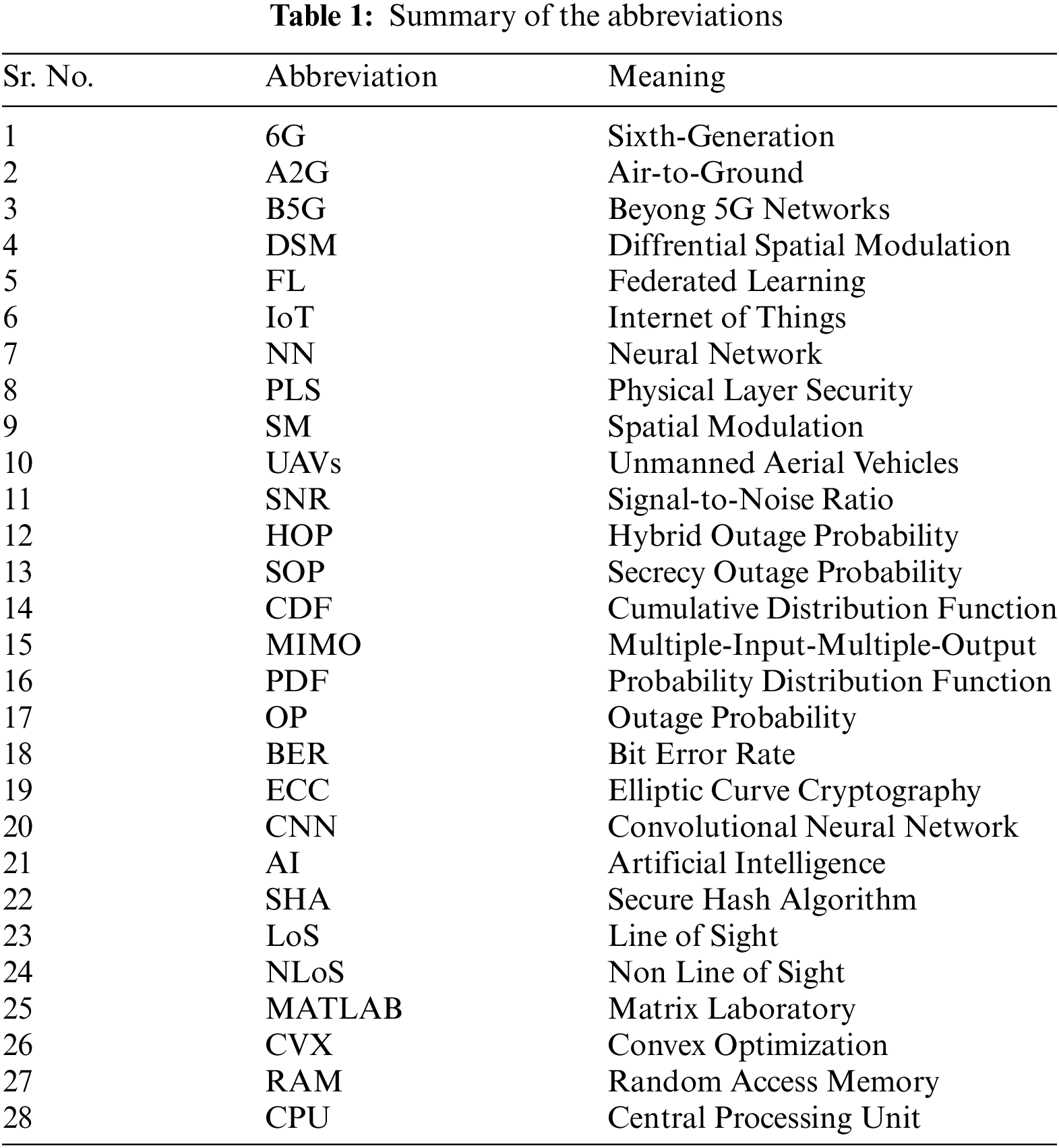
A continuous 1000× increase in network capacity has driven the evolution of wireless networks to date. Despite this growing demand for wireless capacity, the Internet of Everything (IoE) system requires ultra-reliable, low-latency communications. To meet the demands of this new breed of services, we must address unusual challenges, such as characterizing the fundamental rate-reliability-latency tradeoffs that govern their performance, unlocking frequencies beyond sub-6 GHz, and transforming wireless systems into intelligent, self-sustaining networks. The forthcoming sixth-generation (6G) wireless system, with an architecture naturally adapted to the needs of IoE applications and related technological advancements, can potentially address these issues [1]. In recent years, there has been a focus on research on UAVs, also called drones, due to their numerous application fields, autonomy, and adaptability. A wide range of industries, including the military, telecommunications, medical supply delivery, surveillance, monitoring, and rescue missions, have utilized UAVs. When deployed and operated appropriately, UAVs can address various real-world problems [2]. Unauthorized receivers have the potential to intercept information signals sent across wireless Line of Sight (LoS) channels, increasing the risk of information leakage. Wireless UAV transceivers, however, are susceptible to malevolent jamming attempts. For this reason, security in UAV wireless communications is crucial. Regretfully, conventional encryption methods are energy-intensive and require a high level of computer complexity. Physical layer security (PLS) effectively and efficiently protects wireless communication networks by taking advantage of the inherent unpredictability of wireless channels [3]. Table 1 summarises the abbreviations used in the paper and their meanings.
Smart cities utilize advanced technologies like drones, robotics, artificial intelligence (AI), and IoT to enhance life quality, reduce waste, and act as sustainable resource ecosystems. These technologies enhance service quality, energy efficiency, and connection, supporting applications in the fields of healthcare, e-waste reduction, transportation, agriculture, defense, disaster prevention, environmental protection, service delivery, energy conservation, and communication. To improve smart city applications, the reference [4] examined possible methods and uses of collaborative drones and IoT, with an emphasis on data collection, security, privacy, safety for people, disaster prevention, consumption of energy, and quality of life.
Furthermore, Edge Intelligence employs AI to support B5G requirements, with drones serving as relay stations for data collection. Federated learning (FL) improves global model accuracy in smart environments. However, its use is limited by security and decentralization management challenges. Blockchain offers privacy-preserving data sharing but still faces challenges like scalability and energy efficiency. This survey explores the synergy of FL and blockchain for green, sustainable environments, discussing challenges, opportunities, and future trends [5]. Using an AI framework, the reference [6] created a smart cellular architecture for UAV wireless communication. The framework includes self-organizing maps and an NN fitting tool. Validated in a proof-of-concept scenario, it demonstrates high levels of adaptive wireless communication forecasting and achieves efficient and optimized automatic design without human intervention. The reference [7] investigated blockchain technology, which can support smart farming with the goals of increasing productivity, lessening environmental effects, and automating farmer tasks. It suggests a safe blockchain-based system for secure communication between drones and sensors that makes use of the Secure Hash Algorithm (SHA)-256 hash function encryption and the ECC authentication algorithm. A proof-of-concept deployment on the Ethereum blockchain demonstrated the framework’s viability and its potential to address data availability and integrity challenges in smart farming.
The reference [8] presented a national research project that aims to use a digital elevation model and a 3D structure change detection model to enable the autonomous operation of UAVs. The UAVs receive training from a Convolutional Neural Network (CNN) for autonomous flight and terrain identification. The UAVs can detect water flows with 99.6% accuracy in areas with limited satellite images. The study also looks at how channel correlation affects spatial modulation (SM) and differential spatial modulation (DSM) [9], keeping baseband technologies in mind. It emphasizes how crucial channel correlation is to greater spectral efficiency in DSM and SM. In Rayleigh fading channels, the analysis takes into account three send and two receive antennas. The results demonstrate that DSM-BER improves with higher modulation schemes, with the receiving antenna side more affected by spatial correlation or antenna spacing.
In reference [10], researchers examined opportunities for enhanced physical layer security in UAV communication, taking into account PLS technology. A PLS-based UAV communication solution for 5G and beyond networks has been investigated in [11], illustrating the static and mobile deployment of UAVs. In reference [11], researchers proposed a PLS-based study of UAV-powered communication networks. They presented an evaluation of various ground-to-air channel links in a UAV-based communication network, providing a basic concept of the ground-to-air channel. The references [12,13] focused on UAV-aided vehicular communications, deriving insights into architecture, intelligence, and research challenges.
Over the past few years, UAV applications in military, civil, and commercial areas have also made significant progress. However, challenges in high-speed communication links, flexibility in control strategies, and collaborative decision-making algorithms swirl around autonomy, robustness, and reliability. The resulting enhanced Swarm focus on more collaborative communication allows groups of swarming UAVs to self-organize and collaborate, which leads to higher fault tolerance and efficiency [14,15]. Additionally, in [16] a K-means online learning routing protocol (KMORP) was presented for UAV ad hoc networks. This protocol gets around the problems that traditional routing algorithms have with fixed nodes and predetermined network topologies. The KMORP includes a 3D Gauss Markov mobility model for accurately predicting where a UAV is, as well as a K-means online learning method for dynamic clustering and load balancing. It can swiftly adapt to network fluctuations, simultaneously broadcasting fewer messages and sending or receiving more packets, thereby enhancing network performance through packet resending. However, this rapid expansion of consumer UAVs also creates new business opportunities for cellular operators. When integrated into the cellular network as user equipment (UE), UEs like UAVs can generate significant revenue and enhance coverage, spectral efficiency, network quality, and user experience. Although standardization bodies are still exploring ways to service commercial UAVs with cellular networks [17], industries have already begun pilot trials of such prototype models.
Reference [18] examined the current state of UAV-PLS and its implementation in both military and civil applications. A new air-to-ground channel and aerial distributions of the node model are part of this. So are UAV roles in PLS and performing secrecy system secrecy, as well as improving static deployment-based UAV systems through secrecy analysis. It also discusses the methodologies employed in the field of UAV-PLS, as well as the relevant literature, research directions, and challenges. Furthermore, this letter examines the use of relay nodes for secure communications in wireless communication and investigates transmit optimization in a four-node channel model. The authors solved the nonconvex secrecy rate maximization problem by introducing the difference-of-concave program and proposing an iterative algorithm. It is a computationally efficient algorithm with a closed-form solution that improves secrecy via relay, which outperforms static relaying.
1.3 Motivations, Novelties and Contributions
From the common limitations presented in the literature, it has been noticed that future 6G services will significantly focus on surveillance, monitoring, and even UAVs as base stations for various multimedia and infotainment applications. However, due to the broadcast nature of wireless links, the transmission path remains vulnerable to malicious attacks. Furthermore, it is crucial to implement an analytical framework for the 6G channel model, as it enhances the impact of mobility. Therefore, this work presents a novel analytical framework for 6G UAV-aided vehicular communications to restrict passive attacks done by malicious users. We consider the static deployment of the UAVs in the air, which is similar to the deployment of roadside units for vehicular communications. Specifically, we aim to evaluate and secure the vehicle-to-infrastructure link. With the given air-to-ground (A2G) link under the coverage area, we obtained closed-form formulas for the SNR received while accounting for mobility. The derived expressions are helpful in computing the hybrid outage probability (HOP) and secrecy outage probability (SOP). The expressions also provide information on the vehicle’s maximum transmission power and the impact of its distance from UAVs.
1.4 Objectives of This Research
• Analyze the Performance of First-Order Secrecy Metrics: Preliminarily, we analyzed the HOP and SOP over 6G-assisted UAV systems and studied the effect of air-to-ground channel properties for both LoS and NLoS (Non-Line of Sight) communication scenarios.
• Introduce an Optimization Technique for Eavesdropping Mitigation: We propose a new approach to tackle passive eavesdropping in UAV-assisted vehicular environments and calculate the first-order secrecy metrics and lower and upper bounds to improve security.
• Analyze the Role of Mobility in Security: We present a Closed-Form Expression of HOP and SOP in the Nakagami-m Channel, analyzing the role of mobility in security with a single legitimate receiver and an eavesdropper with MIMO Nakagami-m channel. Later, we investigated the impact of UAV mobility on an eavesdropper’s ability to intercept legitimate communications on LoS links.
The network structure describes a scenario where a UAV serves as a communication node for a legitimate broadcaster and receiver. Fig. 1 illustrates the scenario in which a UAV functions as a communication node for vehicles. Usually, the automobile (
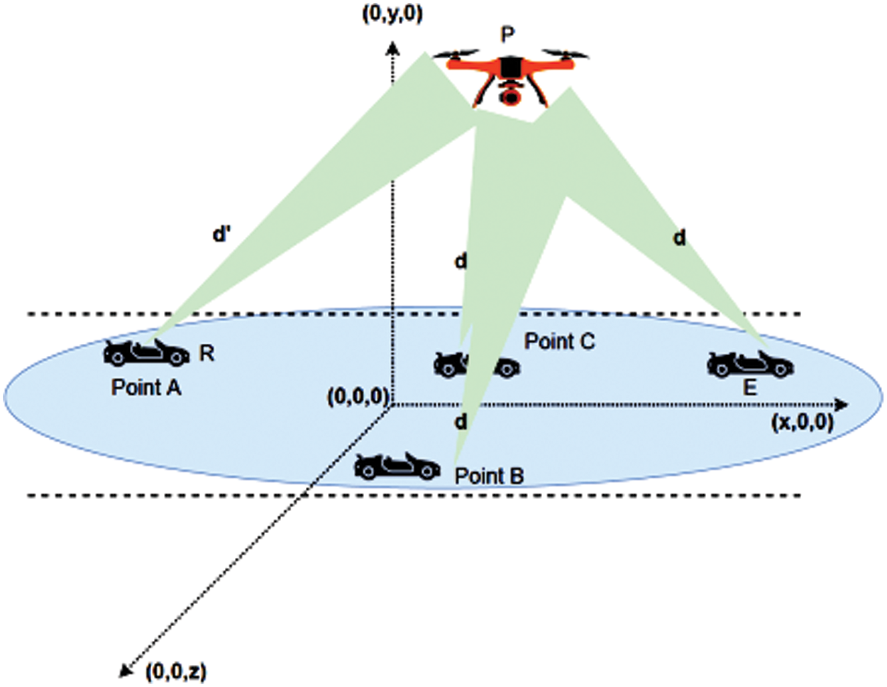
Figure 1: Network model with UAVs and passive mobile eavesdropper
The dynamic fading condition is assumed. To determine the practical applicability, the wiretap channel model for the eavesdropping scenario has been taken into consideration [19]. The dynamic 2
The channel status data is thought to be accurate. According to the joint eigenvalues of 2
where, the terms
The mathematical structure of the signals received on both the legitimate receiver side and the eavesdropper side is represented by the signal model. The ideal transmit antenna index is ascertained as:
where, an average power limitation is applied to the codeword, i.e.,
where,
The signal received at the authorized receiver side is implied by the above equation. Additionally, the received signal vector in the eavesdropper’s channel during time slot l is provided by:
The following is an additional expression of the h as a function of the distance between the authorized transmitter and the eavesdropper [21]:
where,
3 Examination of First-Order Secrecy Measures for the 6G-UAVs System
This section focuses on the performance analysis of a hypothetical UAV vehicular network. In contrast with [13–16], the current work considers the updated, generic but tractable vehicular scenario in terms of the vehicle mobility and path loss exponent. The earlier work [13] did not demonstrate the effect of path loss on the effectiveness of secrecy metrics. However, in the UAV-enable scenario, the proposed work focuses on the multiple positions of the legitimate receiver, starting from point A to point C (Fig. 1). The car, which has two antennas, starts its journey from point A to point C. The legitimate transmitter also has a dual antenna, thus resulting in a MIMO scenario. In the presence of small-scale fading and vehicle mobility, it is advantageous to consider the dynamic fading channels for better modeling of the performance metrics. Therefore, this work involves the 2
The proposed workflow is shown in Fig. 2, in addition, the paper is structured as follows: Section 3.1 first generates the analytical closed-form expression for the received SNR. Subsequently, Section 3.2 carries out the analysis of SOP, while Section 3.3 proceeds with the HOP analysis. Section 4 focuses on knowing outage probability (OP) and SOP limits, while Section 5 focuses on the optimization method of restricting eavesdropping, followed by numerical results in Section 6.
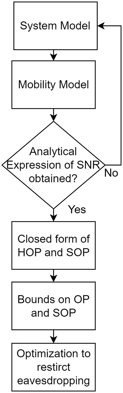
Figure 2: Flowchart of workflow
3.1 Analytical Closed-Form of Received SNR for 6G UAVs MIMO System
Vehicle mobility’s PDF is given by [22]:
where, the parameters of the road structure are
For above, Eq. (10) has been re-denoted as
The given Eq. (11) represents the CDF
where,
3.2 Analysis of the Probability of Secrecy Outage
This section looks at the likelihood of a secrecy outage on the legitimate receiver side. However, since the legitimate transmitter lacks the channel state information for the eavesdropper’s channel, it is forced to encode data at a constant code rate
The eavesdropper and legitimate receiver have received SNRs of
The transmitter power at S in the hybrid network of the 6G-UAVs system can be expressed as shown in [22–24].
Given a maximum broadcast power of
3.2.1 First Integral Term Derivation
The outer part of the
The
The SOP is defined as follows after additional solution with the help of [11, Section IV]:
The function
3.3 Derivations of Hybrid Outage Probability
This section computes the likelihood of a power failure based on the starting locations of a sanctioned transmitter node. An outage is a likelihood that the received instantaneous SNR, denoted as
The fading envelope caused by the mobility is equal to the resultant channel gain, as demonstrated in (8). Additionally, Jake’s correlation function is not a random variable with a specific coding rate. The system’s ability to tolerate more information than a particular rate
Using [11, Section IV] to solve the preceding expression, the outage probability is as follows:
It is evident from (23) that wireless fading parameters and mobility parameters determine the OP. It implies how the speed of the authorized receiver may affect the likelihood of being overheard.
4 The Importance of Knowing the Limits of Secrecy Metrics
In this section, we derive the upper and lower bounds of PLS metrics. These metrics are crucial for gauging the potential for eavesdropping. In essence, they assist us in assessing the security of our communication and detecting any unauthorized access.
The outage probability measures the likelihood of a communication security breakdown. We require a secrecy capacity that is higher than the target secrecy rate. This capacity is the difference between the legitimate communication link’s capacity and the eavesdropper’s link. This stops the transfer of information between the eavesdropper’s channel and the main channel. We express this mathematically as follows:
Although this expression is well articulated, it is important to consider the impact of noisy fading channels on the range of secrecy rates (
To handle this expression more effectively, we convert it into an inequality, as shown in [25], to explore its integral variations for convex optimization.
4.1.1 Lower Bound of Outage for 6G UAV System
Denote
In the system,
We may reduce the given equation even more by substituting
The above expression of OP reveals that the non-linear medium parameter affects the lower bounds.
4.1.2 Upper Bound of Outage for 6G UAVs System
Let’s denote
Like the lower limit, the condition states that there must be an unlimited number of coefficients for a closed-form integral on each side of
Substituting
This expression demonstrates that the maximum limit is influenced by the quantity of antennas and the fluctuating distance from the authorized transmitter.
4.2 Comprehending the Probability of a Secrecy Outage
This section delves into the concept of SOP and its bounds, as represented by Eq. (19).
4.2.1 Lower Bound of Secrecy Outage for 6G UAVS System
Denote
Now, using this phrase, we can represent the minimum value of SOP as (24). By replacing Eq. (19) with the previous expression and simplifying it, we can establish the minimum value for the range from
4.2.2 Upper Bound of Outage for 6G UAV System
The upper limit of SOP is achieved when a certain constraint parameter tends toward zero. This occurs when
Now, based on this expression, we can express the upper bound of SOP as (25). After substituting (23) into the given expression and simplifying, The maximum limit for the area ranging from
The above expression demonstrates that as k approaches infinity [27], Chebyshev’s inequality is satisfied and simplifies to an exponential term. Additionally, it’s notable that by substituting
5 Restricting Eavesdropping for 6G-UAVs System through an Optimisation Problem
This study aims to develop a solution that reduces passive eavesdropping in connected vehicular scenarios. In this context, the term SNR pertains to users engaging in secure transmissions. Because the scenario is clandestine, pinpointing the eavesdropper is inherently challenging.
The proposed solution aims to reduce passive eavesdropping in connected vehicular scenarios. Fig. 3 illustrates the possible conditions under which eavesdropping can occur with respect to the performance of SOP against SNR. Typically, when the secrecy rate (
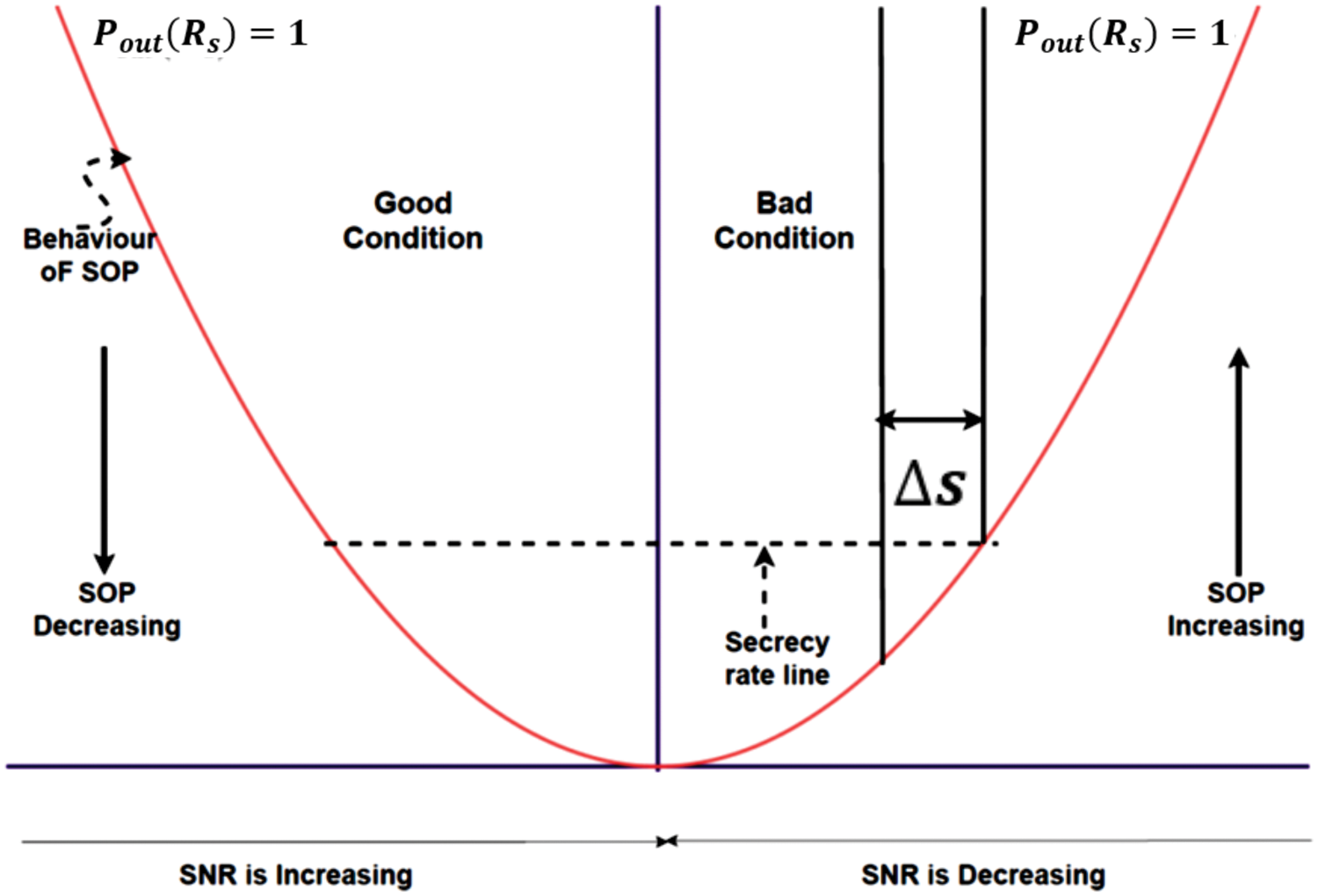
Figure 3: Convex optimisation scenario for restricting eavesdropping
The optimization approaches are created to prevent eavesdropping in unfavorable settings. The convexity of the problem is demonstrated by Theorem 1, while Theorem 2 offers a way to limit eavesdropping.
Theorem 1: There is a domain
Proof: SOP cannot be defined as a minimum or maximum at any moment. On the other hand, limitations can be created for a certain domain of fading coefficients. Consequently, the issue is classified as convex optimization. The following is the proof:
Specify a period
The concept mentioned above can be further defined as follows:
Using the SOP expression from 19, the additional term in the equality above can be expressed as 26. There is no evidence to support the aforesaid equality. Thus, convex optimization can be used to solve Theorem 1.
Theorem 2: The falsification factor (
Proof: Depending on the orientation of the intervals, there are three subclasses for the convex optimization problem.
1. Subclass 1: If
2. Subclass 2: If
3. Subclass 3: If
The difference between the intended value
From (38), it is evident that the expression yields an optimal root given the specified restrictions. There is availability of the optimal root when
The following is how
1. If
2. If
3. If
The direction factor indicates whether OP is going in a tractable direction—that is, rising or decreasing. As a result, the falsification factor can be zero, positive, or negative. Furthermore, the direction factor is manageable, indicating that command over the falsification element may be assumed, consistently creating an atmosphere that is resistant to eavesdropping. Controlling the eavesdropping can be achieved by adding a negative
This section contains simulation details to validate SOP’s analytical expression. We performed these simulations using the optimization and mathematical toolbox of MATLAB (Matrix Laboratory) R2022b. More precisely, the convex optimization (CVX) tool was used to formalize SOP coefficients so that the tasks could be optimized. This required a mix of nonlinear, analytical, and convex methods to validate the problem. We used Monte-Carlo simulations with about 108 generations. Both analytical and non-linear methods are used to draw inferences from the results.
The former is the analytical expression’s ultimate form, incorporating the direct reliance on single or multiple variables on metrics such as SOP and OP performance. The performance metric incorporates the wireless medium parameter in its non-linear form; however, the final formulation does not account for this factor. We review the methodology, emphasizing how the vehicle’s motion, the wireless medium parameter, and the corresponding mathematical parameters affect the effectiveness of SOP and OP. In all numerical results,
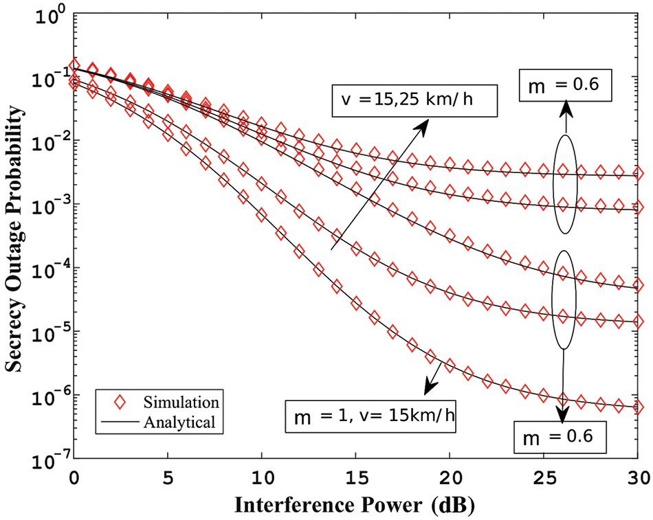
Figure 4: (
Fig. 5 displays the maximum limit integral of the outage probability vs. series convergence terms. The upper bound is achieved by equating the range between the authorized emitter and the eavesdropper to 100 meters. It represents that as the outage performance quickly approaches unity for higher series terms of more than six, raising the secrecy rate is required. Fig. 6 displays the secrecy outage probability performance against SNR at various velocities. The fact that the secrecy outage is only 0.4 indicates that more secure information transfer is taking place between authorized transmitters and authentic receivers, thanks to appropriate modeling of the fading environment.
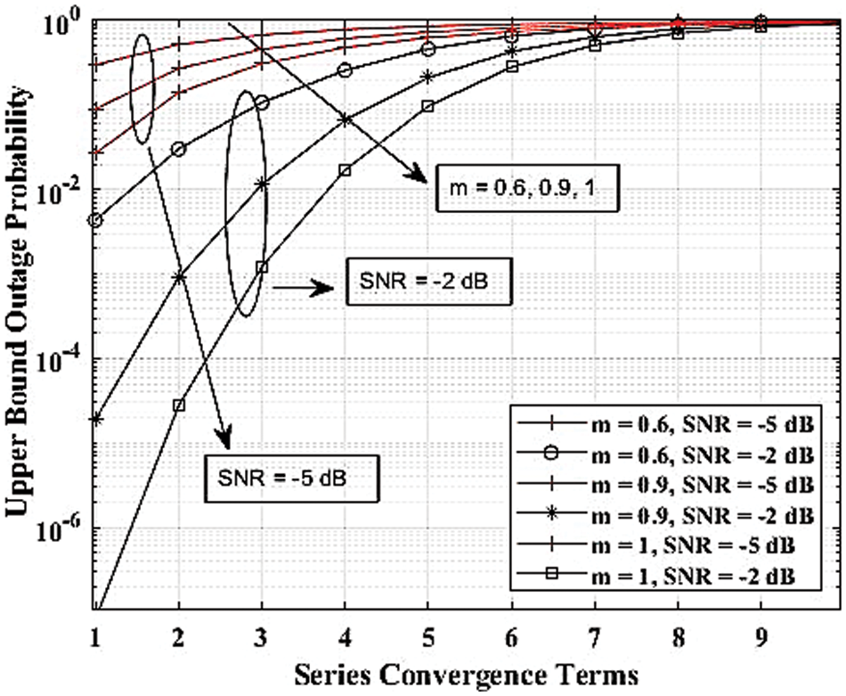
Figure 5: OP’s maximum limit integral vs. the convergence terms, where
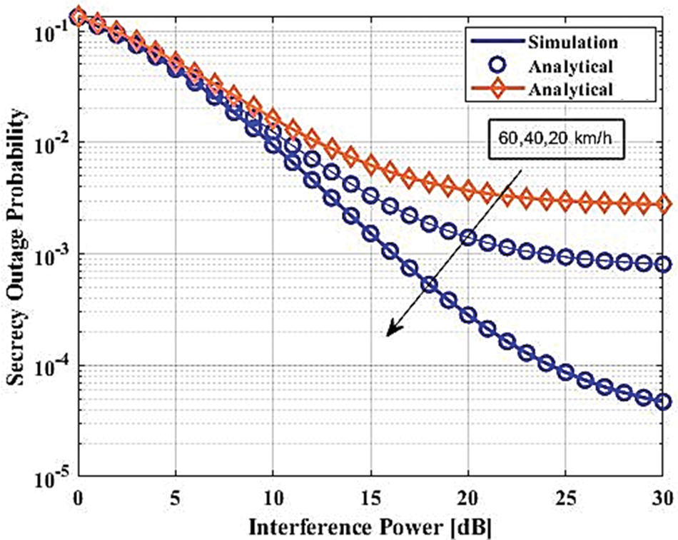
Figure 6: The SOP is compared to the SNR with
As demonstrated in Fig. 7, however, the wireless medium is quite unpredictable, necessitating the determination of the lower and upper bounds. Additionally, it shows how well the SOP performs in comparison to the bound index. The analytical form of the SOP allows for the identification of the hyper-geometric special function. This function assists in finding the infinite series using closed-form methods. The bound index determines the number of iterations after which we can treat the expression as closed form. Fig. 8 illustrates the SOP’s performance in relation to the bound index of the hypergeometric function. It is evident that when the index rises, the SOP expresses itself more accurately, reducing the likelihood of being overheard when mobility is at its peak.
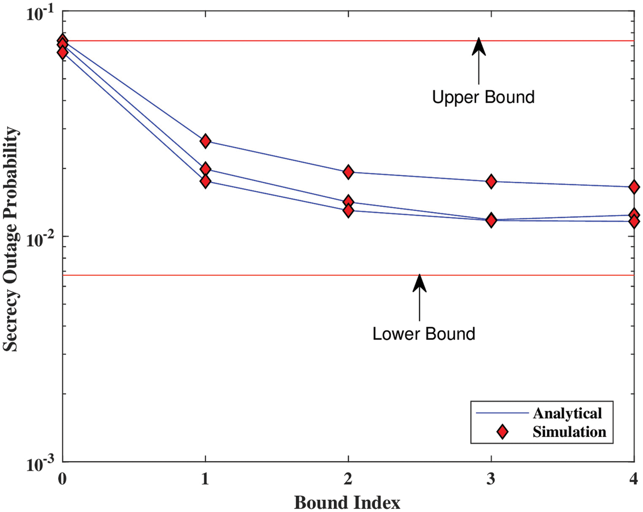
Figure 7: Using the bound index to guide decision-making (
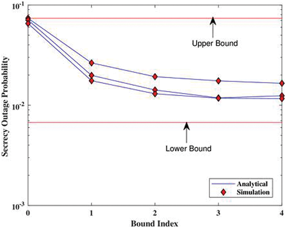
Figure 8: Coefficient of optimization roots (
Fig. 8 displays the counting of the roots of the SOP closed-form expression. The nonlinear technique does not provide the exact number, and it may vary up to infinity. We have observed that root identification is dependent on the sign of the falsification factor. This suggests that the procedure is cognizant of SOP’s increasing and lowering values. Fig. 9 shows the ability of Theorem 2 to find the optimization roots over Eigenvalues provided by the characteristic expression of SOP. The behavior demonstrates that the convex technique performs better when applied to closed-form expressions because it converges quickly toward zero at very low Eigenvalues. In that scenario, however, the direction factor’s value should be known. In practice, we can use it to ensure that the SOP increases in value whenever the eavesdropper initiates the process of breaking into the communication link. Applying the predefined negative direction factor reduces the effectiveness of eavesdropping in that situation. In practice, the Reed-Muller codes can be used to enforce them on the system.
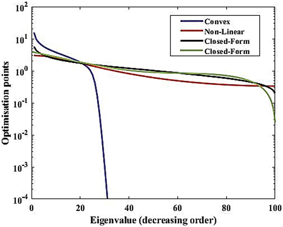
Figure 9: Optimization roots for anti-eigenvalues (
Accordingly, Fig. 10 demonstrates that the convex approach is appropriate for the optimization. The convex approach optimizes the falsification factor more effectively than the non-linear and closed-form approaches. Fig. 11 presents the insights into exact roots obtained from the closed form, convex, and non-linear approaches. Unlike Fig. 6, we show the asymptotic behavior of SOP for
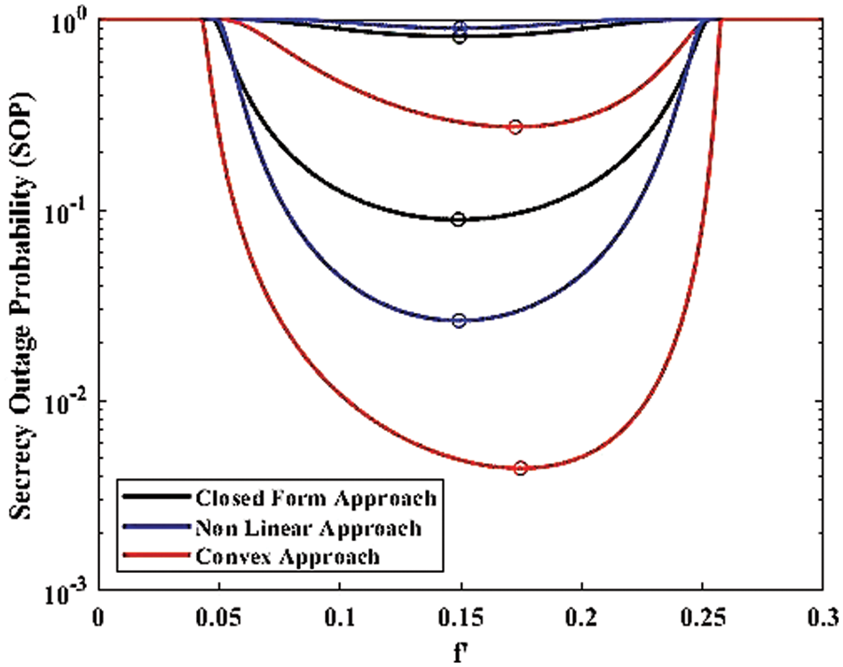
Figure 10: SOP for preventing falsification (
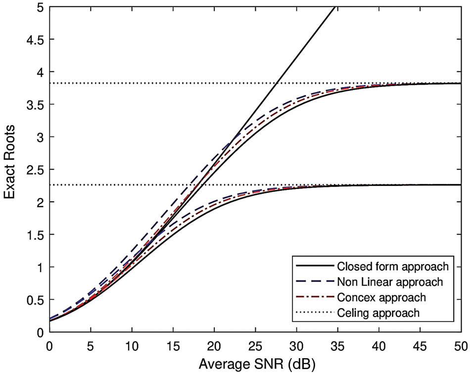
Figure 11: Exact roots for
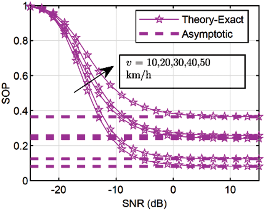
Figure 12: Asymptotic behavior of SOP (
Figs. 13 to 15 show the outcomes of a closed-form method and its non-linear version. The first one pertains to the final form of the analytical statement and includes the measurement of the direct relationship between one or more variables and metrics like SOP and HOP. However, the final expression of the non-linear performance metric does not include the wireless medium parameter. This study looks at how wireless medium variables, vehicle mobility, and the mathematical parameters that go along with them affect how effective SOP and OP are.
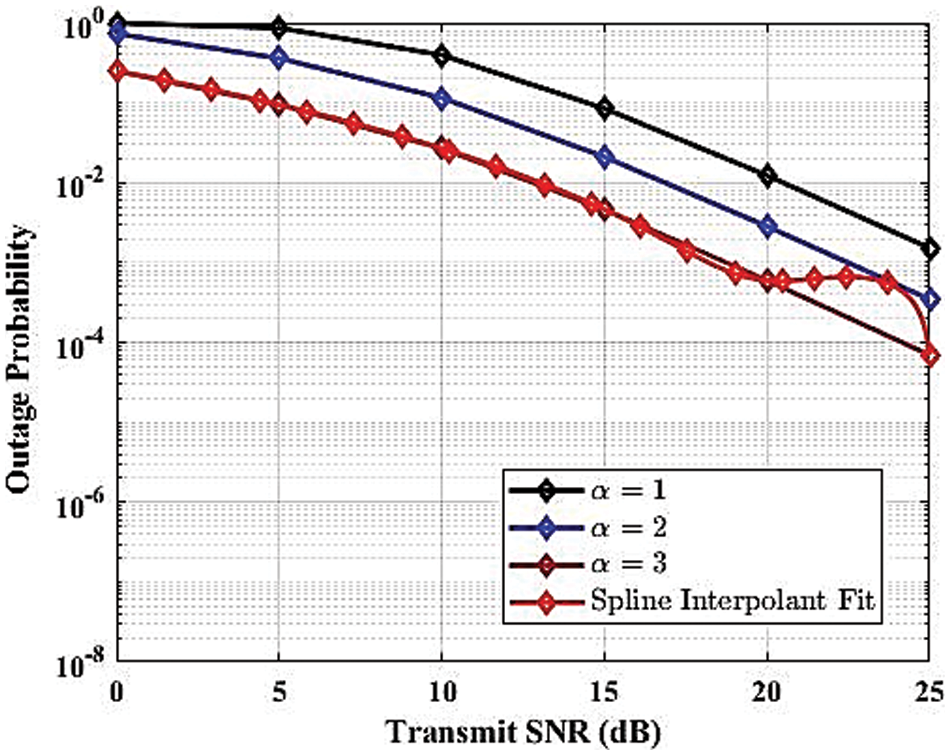
Figure 13: Outage probability against transmit SNR for various path loss
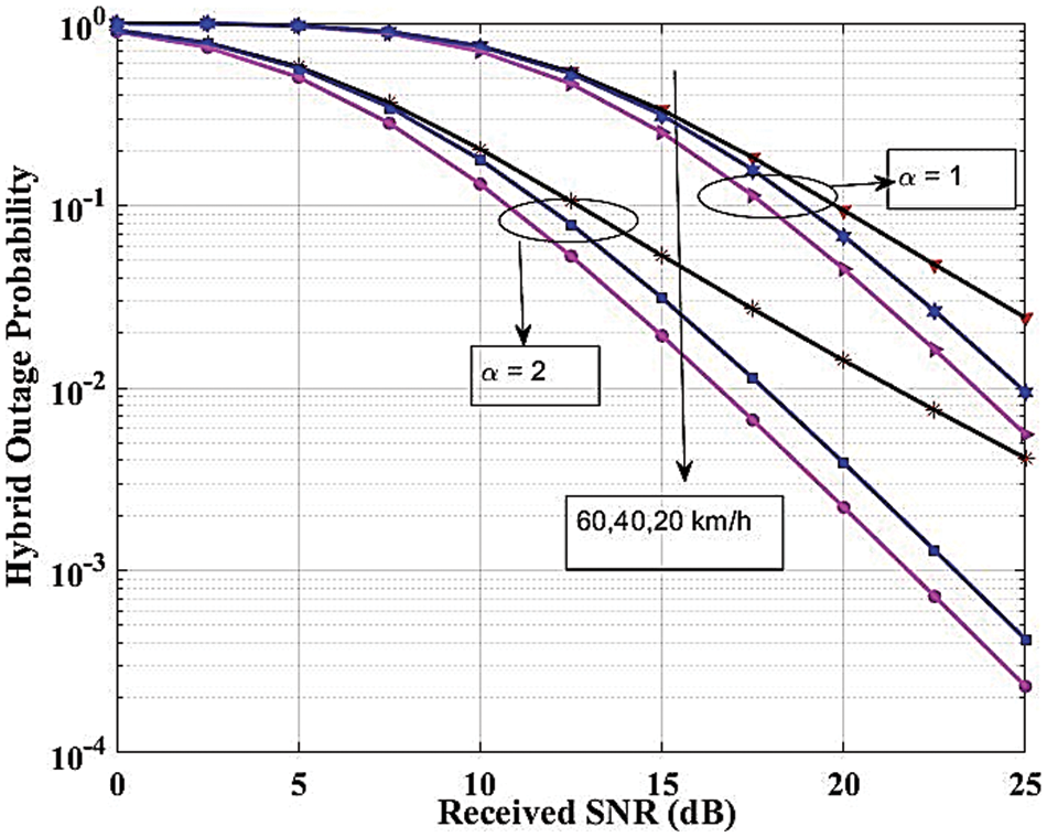
Figure 14: Hybrid outage probability against transmit SNR for various velocity
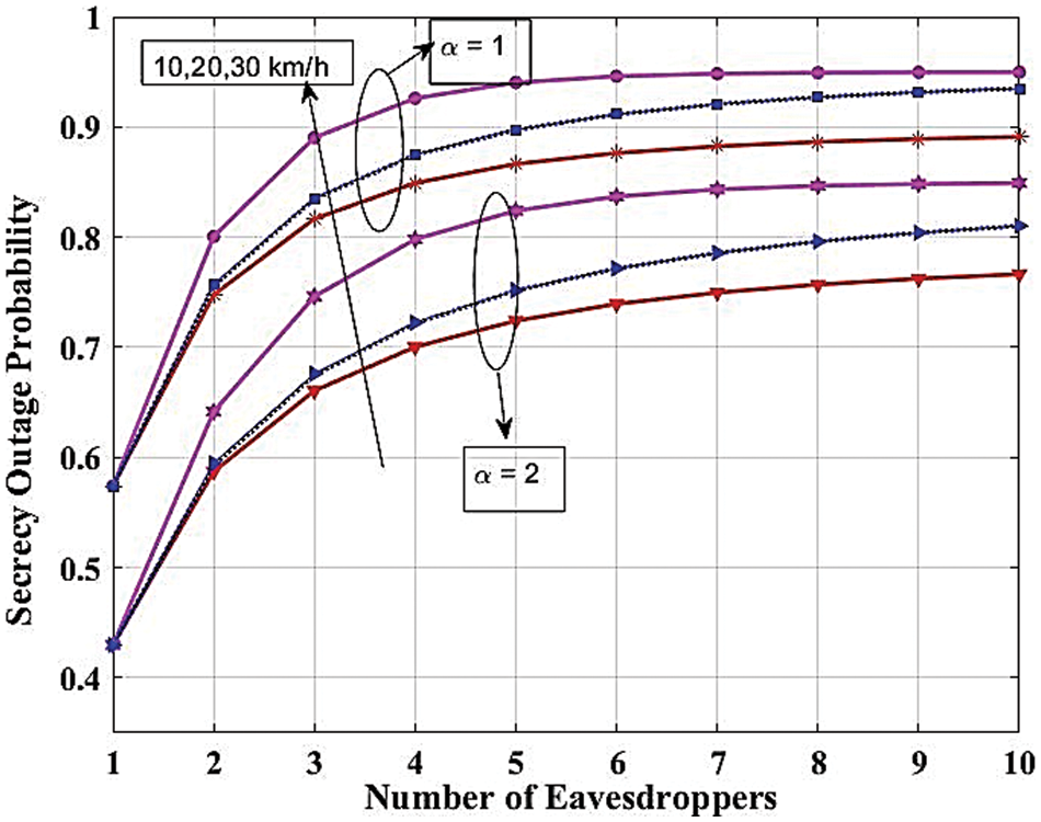
Figure 15: Secrecy outage probability against the number of eavesdroppers
SOP vs. SNR function for Nakagami-m fading channels is plotted in Fig. 16, focusing on different fading parameters (m) of the legitimate and eavesdropping channels. The output is the SOP vs. the SNR (dB) with three different Nakagami-m parameters (m = 1), (m = 2), and (m = 3) using a logarithmic scale for the SOP. The m values distinguish between a legal channel and an eavesdropper channel, represented by the curves on the plot. Curves in blue, yellow, and green color represent legitimate channels regarding m = 1, m = 2, and m = 3, respectively (Fig. 6). In contrast to the eavesdropper channels for both m and values, the SOP experiences a decrease across all scenarios as the SNR rises, due to the plot’s clear display of strong secrecy performance at elevated SNR levels. Still, the secrecy outage probability is never zero, i.e., the SOP is zero for all block lengths. Higher m values correspond to curves lying lower on the graph, indicating that better secrecy performance is present in channels with higher m values. Higher m values correspond to less severe fading conditions. Also, it is evident from the valid and eavesdropper channels. For all m, the eavesdropper channels have higher SOP than the corresponding legitimate channels which means that the eavesdropper experiences worse secrecy performance than the legitimate user. In general, Fig. 16 well reveals that the secrecy outage performance of wireless communication systems can be significantly influenced by the parameter of Nakagami-m fading and also SNR and that the Ser can be greatly improved by increasing SNR and by adopting the large m value.
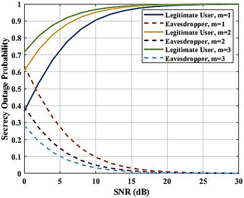
Figure 16: SOP against SNR with various channel parameters
Fig. 17 illustrates the SOP as a function of eavesdropper velocity for Nakagami-m fading channels with a fading parameter (m = 2). The SOP, plotted on a logarithmic scale, measures the likelihood that the secrecy capacity falls below a threshold of 0.1. The x-axis represents the eavesdropper’s velocity in meters per second (m/s), ranging from 0 to 30 m/s. As the eavesdropper’s velocity increases, the SOP exhibits significant fluctuations, indicating variability in secrecy performance due to the Doppler effect, which alters the channel conditions for the eavesdropper. These fluctuations highlight the SOP’s sensitivity to changes in the eavesdropper’s velocity. The lack of a clear trend may be due to the complicated interaction between the Doppler shift and Nakagami-m fading, which changes the quality of the received signal and, in turn, the SOP. This underscores the importance of considering mobility in secure communication analysis, as varying eavesdropper velocities can substantially affect the system’s secrecy performance.
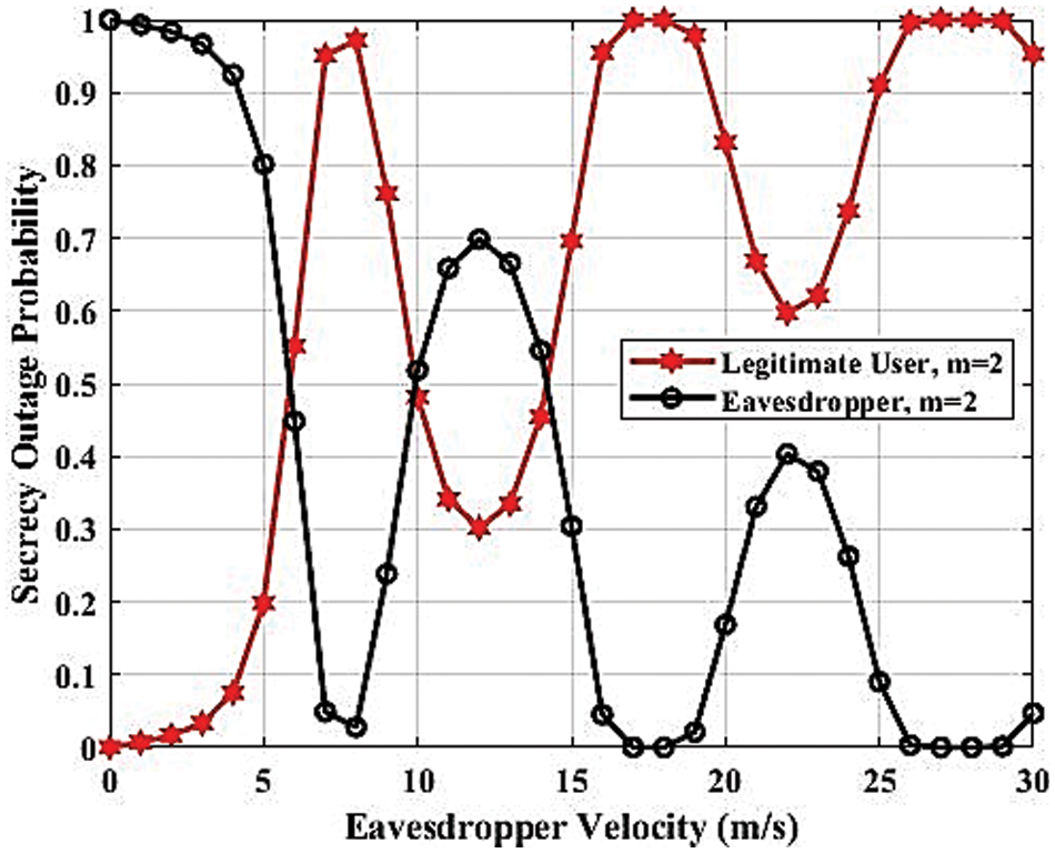
Figure 17: SOP against velocity
6.1 The Influence of Parameters on Outcomes
The influence of each parameter on the performance of secrecy is explicated in the following manner:
1. The effect on high fading parameters: The fading parameter frequently switches to dynamic fading, which is a more realistic depiction for a vehicular scenario, when it is given a significant value (
2. The findings indicate that in the context of analytical representations (Eq. (17)) of SOP, the utilization of several antennas yields significantly superior performance compared to a single antenna. In the extremely variable fading situation (
3. The influence of the convex approach: Fig. 1 illustrates how the requirement for limitation increases as the SNR decreases. For instance, when the SNR is set at 0.2, the required value of SOP is observed to grow to 0.7. As stated in reference [15], the falsification factor should be designed to maintain the optimal value of SOP. Therefore, in accordance with Theorem 2, the direction factor value of 1 is included into the system, thereby restricting the occurrence of eavesdropping. Various numerical methods, both fast and slow, have been examined as potential measures to mitigate eavesdropping activities. The convex technique has been seen to rapidly identify outlier roots. Consequently, the falsification factor is designed in a manner that prevents the standard deviation from exceeding a specific desired value.
4. The precise modeling of dynamic fading factors is crucial when dealing with extreme fading circumstances. Hence, a high dynamic fading parameter frequently signifies precise modeling, thereby enhancing the performance of secrecy. The outage probability exhibits fast variation in response to changes in velocity when the fading parameter is high. The issue can be addressed and resolved by taking into account an appropriate fading model.
5. Velocity has an effect in that large variations in SNR may result from increasing receiver-side velocity. The receiver’s signal reconstruction will yield imprecise approximations of the original transmitted signal. As a result, considering the higher velocity during processing will directly affect the signal reconstruction. Thus, the fading scenario gets better as node velocity increases, which raises the probability of incursion.
6. The process of obtaining information from outside sources: The functions defined by the non-linear coefficient of the wireless communication medium are referred to as the computed bounds. The constraints exhibit a static yet conditional nature, indicating that it is not advisable to consistently raise the signal power in the event of the most severe fading scenario. This is supported by the findings presented in Fig. 6, which indicate that the SOP is largely constrained after reaching an indexing value of
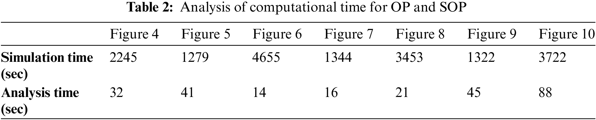
6.2 Analysis of Computation Time
The computation time for each result was the main emphasis of this section. 8 GB of RAM (Random Access Memory)) and an Intel(R) Core(TM) i7-4790 CPU (Central Processing Unit) operating at 3.60 GHz were used to run the Monte-Carlo simulations.
Table 2 illustrates the computational time required for plotting analytical expressions of OP and SOP (referred to as analysis time) and the Monte Carlo simulations (referred to as simulation time). It is noted that the hyper-geometric functions involved in the simulations for Figs. 4, 6, and 8 can significantly reduce the computation time in comparison with the rest of the results.
This paper focuses on the problem of eavesdropping in the context of 6G-enabled UAV communications. Expressions of physical layer security metrics were obtained across a dynamic Nakagami-
Acknowledgement: We extend our sincere gratitude to Taif University, Saudi Arabia, for their invaluable support and collaboration in this research endeavor. Our deepest appreciation also goes to Smt. Chandaben Mohanbhai Patel Institute of Computer Applications and Chandubhai S. Patel Institute of Technology for their significant contributions and unwavering assistance throughout this study. The collective efforts and resources provided by these esteemed institutions have been instrumental in the successful completion of this research.
Funding Statement: This research was funded by Taif University, Taif, Saudi Arabia, Project No. (TU-DSPP-2024-139).
Author Contributions: Study Conception: Sagar Kavaiya and Sagarkumar Patel; Methodology: Sagar Kavaiya and Dharmendra Chauhan; Mathematical Formulation: Sagarkumar Patel; Software: Hiren Mewada and Sagarkumar Patel; Validation and Formal Analysis: Hiren Mewada and Faris A. Almalki; Writing—Original Draft, Visualization: Sagar Kavaiya, Dharmendra Chauhan and Hana Mohammed Mujlid; Writing—Review & Editing: Sagarkumar Patel, Hiren Mewada and Faris A. Almalki; Project Administration and Funding: Faris A. Almalki and Hana Mohammed Mujlid. All authors reviewed the results and approved the final version of the manuscript.
Availability of Data and Materials: Data sharing is not applicable to this article as no datasets were generated or analyzed during the current study.
Ethics Approval: Not applicable.
Conflicts of Interest: The authors declare that they have no conflicts of interest to report regarding the present study.
References
1. W. Saad, M. Bennis, and M. Chen, “A vision of 6G wireless systems: Applications, trends, technologies, and open research problems,” IEEE Netw., vol. 34, no. 3, pp. 134–142, 2020. doi: 10.1109/MNET.001.1900287. [Google Scholar] [CrossRef]
2. M. Mozaffari, W. Saad, M. Bennis, Y. H. Nam, and M. Debbah, “A tutorial on UAVs for wireless networks: Applications, challenges, and open problems,” IEEE Commun. Surv. Tutorials, vol. 21, no. 3, pp. 2334–2360, 2019. doi: 10.1109/COMST.2019.2902862. [Google Scholar] [CrossRef]
3. X. Sun, D. W. K. Ng, Z. Ding, Y. Xu, and Z. Zhong, “Physical layer security in UAV systems: Challenges and opportunities,” IEEE Wirel. Commun., vol. 26, no. 5, pp. 40–47, 2019. doi: 10.1109/MWC.001.1900028. [Google Scholar] [CrossRef]
4. S. H. Alsamhi, O. Ma, M. S. Ansari, and F. A. Almalki, “Survey on collaborative smart drones and internet of things for improving smartness of smart cities,” IEEE Access, vol. 7, pp. 128125–128152, 2019. doi: 10.1109/ACCESS.2019.2934998. [Google Scholar] [CrossRef]
5. S. H. Alsamhi et al., “Drones’ edge intelligence over smart environments in B5G: Blockchain and federated learning synergy,” IEEE Trans. Green Commun. Netw., vol. 6, no. 1, pp. 295–312, 2022. doi: 10.1109/TGCN.2021.3132561. [Google Scholar] [CrossRef]
6. E. S. Alkhalifah and F. A. Almalki, “Developing an intelligent cellular structure design for a UAV wireless communication topology,” Axioms, vol. 12, no. 2, 2023, Art. no. 129. doi: 10.3390/axioms12020129. [Google Scholar] [CrossRef]
7. K. S. Alqarni, F. A. Almalki, B. O. Soufiene, O. Ali, and F. Albalwy, “Authenticated wireless links between a drone and sensors using a blockchain: Case of smart farming,” Wirel. Commun. Mob. Comput., vol. 2022, no. 1, 2022, Art. no. 4389729. doi: 10.1155/2022/4389729. [Google Scholar] [CrossRef]
8. F. A. Almalki and M. C. Angelides, “Autonomous flying IoT: A synergy of machine learning, digital elevation, and 3D structure change detection,” Comput. Commun., vol. 190, no. 1, pp. 154–165, 2022. doi: 10.1016/j.comcom.2022.03.022. [Google Scholar] [CrossRef]
9. S. Patel et al., “Impact of antenna spacing on differential spatial modulation and spatial modulation for 5G-based compact wireless devices,” in 2021 4th International Symposium on Advanced Electrical and Communication Technologies (ISAECT), Alkhobar, Saudi Arabia, Dec. 6–8, 2021, pp. 1–6. doi: 10.1109/ISAECT53699.2021.9668400. [Google Scholar] [CrossRef]
10. W. U. Khan et al., “Opportunities for physical layer security in UAV communication enhanced with intelligent reflective surfaces,” IEEE Wirel. Commun., vol. 29, no. 6, pp. 22–28, 2022. doi: 10.1109/MWC.001.2200125. [Google Scholar] [CrossRef]
11. A. Omri and M. O. Hasna, “Physical layer security analysis of UAV based communication networks,” in IEEE Veh. Technol. Conf., Chicago, IL, USA, Aug. 27–30, 2018, pp. 1–6. doi: 10.1109/VTCFall.2018.8690950. [Google Scholar] [CrossRef]
12. J. Hu, C. Chen, L. Cai, M. R. Khosravi, Q. Pei and S. Wan, “UAV-assisted vehicular edge computing for the 6G internet of vehicles: Architecture, intelligence, and challenges,” IEEE Commun. Standards Mag., vol. 5, no. 2, pp. 12–18, 2021. doi: 10.1109/MCOMSTD.001.2000017. [Google Scholar] [CrossRef]
13. Z. Yin et al., “UAV-assisted physical layer security in multi-beam satellite-enabled vehicle communications,” IEEE Trans. Intell. Transp. Syst., vol. 23, no. 3, pp. 2739–2751, 2022. doi: 10.1109/TITS.2021.3090017. [Google Scholar] [CrossRef]
14. S. Javaid et al., “Communication and control in collaborative UAVs: Recent advances and future trends,” IEEE Trans. Intell. Transp. Syst., vol. 24, no. 6, pp. 5719–5739, 2023. doi: 10.1109/TITS.2023.3248841. [Google Scholar] [CrossRef]
15. A. Vashisth and R. S. Batth, “An overview, survey and challenges in UAVs communication network,” in 2020 International Conference on Intelligent Engineering and Management (ICIEM), London, UK, 2020, pp. 342–347. doi: 10.1109/ICIEM48762.2020.9160197. [Google Scholar] [CrossRef]
16. Saifullah, Z. Ren, K. Hussain, and M. Faheem, “K-means online-learning routing protocol (K-MORP) for unmanned aerial vehicles (UAV) adhoc networks,” Ad Hoc. Netw., vol. 154, no. 2, 2024, Art. no. 103354. doi: 10.1016/j.adhoc.2023.103354. [Google Scholar] [CrossRef]
17. A. Fotouhi et al., “Survey on UAV cellular communications: Practical aspects, standardization advancements, regulation, and security challenges,” IEEE Commun. Surv. Tutorials, vol. 21, no. 4, pp. 3417–3442, 2019. doi: 10.1109/COMST.2019.2906228. [Google Scholar] [CrossRef]
18. J. Wang et al., “Physical layer security for UAV communications: A comprehensive survey,” China Commun., vol. 19, no. 9, pp. 77–115, 2022. doi: 10.23919/JCC.2022.09.007. [Google Scholar] [CrossRef]
19. S. K. Leung-Yan-Cheong and M. E. Hellman, “The gaussian wire-tap channel,” IEEE Trans. Inf. Theory, vol. 24, no. 4, pp. 451–456, Jul. 1978. doi: 10.1109/TIT.1978.1055917. [Google Scholar] [CrossRef]
20. G. Fraidenraich, O. Lévêque, and J. M. Cioffi, “On the MIMO channel capacity for the Nakagami-m channel,” IEEE Trans. Inf. Theory, vol. 54, no. 8, pp. 3752–3757, 2008. doi: 10.1109/TIT.2008.926467. [Google Scholar] [CrossRef]
21. S. Kavaiya, D. K. Patel, Z. Ding, Y. L. Guan, and S. Sun, “Physical layer security in cognitive vehicular networks,” IEEE Trans. Inf. Theory, vol. 54, no. 8, pp. 3752–3757, Aug. 2008. doi: 10.1109/TIT.2008.926467. [Google Scholar] [CrossRef]
22. S. Zhu, C. Guo, C. Feng, and X. Liu, “Performance analysis of cooperative spectrum sensing in cognitive vehicular networks with dense traffic,” in 2016 IEEE 83rd Vehicular Technology Conference (VTC Spring), Nanjing, China, 2016, pp. 1–6. doi: 10.1109/VTCSpring.2016.7504402. [Google Scholar] [CrossRef]
23. S. Kavaiya and D. K. Patel, “Restricting passive attacks in 6G vehicular networks: A physical layer security perspective,” Wirel. Netw., vol. 29, no. 3, pp. 1355–1365, 2022. doi: 10.1007/s11276-022-03189-1. [Google Scholar] [CrossRef]
24. H. Lei et al., “Secrecy outage performance for SIMO underlay cognitive radio systems with generalized selection combining over Nakagami-m channels,” IEEE Trans. Veh. Technol., vol. 65, no. 12, pp. 10126–10132, 2016. doi: 10.1109/TVT.2016.2536801. [Google Scholar] [CrossRef]
25. I. S. Gradshteyn, I. M. Ryzhik, A. Jeffrey, Y. V. Geronimus, M. Y. Tseytlin and Y. C. Fung, “Table of integrals, series, and products,” J. Biomech. Eng., vol. 103, no. 1, p. 58, 1981. doi: 10.1115/1.3138251. [Google Scholar] [CrossRef]
26. D. E. Barton, M. Abramovitz, and I. A. Stegun, “Handbook of mathematical functions with formulas graphs and mathematical tables,” J. R. Stat. Soc. Ser. A, vol. 128, no. 4, pp. 593–594, 1965. doi: 10.2307/2343473. [Google Scholar] [CrossRef]
27. M. Bloch and J. Barros, “Secrecy limits of Gaussian Wiretap Channel,” in Physical–Layer Security: From Information Theory to Security Engineering, 1st ed. New York, NY, USA: Cambridge University Press, 2011, pp. 177–190. [Google Scholar]
28. Y. Ai, M. Cheffena, A. Mathur, and H. Lei, “On physical layer security of double Rayleigh fading channels for vehicular communications,” IEEE Wirel. Commun. Lett., vol. 7, no. 6, pp. 1038–1041, 2018. doi: 10.1109/LWC.2018.2852765. [Google Scholar] [CrossRef]
Cite This Article
 Copyright © 2024 The Author(s). Published by Tech Science Press.
This work is licensed under a Creative Commons Attribution 4.0 International License , which permits unrestricted use, distribution, and reproduction in any medium, provided the original work is properly cited.
 Downloads
 Citation Tools