
 Submit a Paper
 Propose a Special lssue
 Open Access
ARTICLE
Microstructure and Hot Tearing Sensitivity Simulation and Parameters Optimization for the Centrifugal Casting of Al-Cu Alloy
1 School of Energy and Environmental Engineering (SEEE), University of Science and Technology Beijing (USTB), Beijing, 100083, China
2 Advanced Research Institute of Multidisciplinary Science (ARIM), Beijing Institute of Technology (BIT), Beijing, 100081, China
* Corresponding Author: Ruifeng Dou. Email:
(This article belongs to the Special Issue: Advanced Computer Technology for Materials Characterization, Properties Prediction, Design and Discovery)
Computers, Materials & Continua 2024, 80(2), 2873-2895. https://doi.org/10.32604/cmc.2024.052571
Received 07 April 2024; Accepted 14 July 2024; Issue published 15 August 2024
 View Full Text
 Download PDF
Abstract
Four typical theories on the formation of thermal tears: strength, liquid film, intergranular bridging, and solidification shrinkage compensation theories. From these theories, a number of criteria have been derived for predicting the formation of thermal cracks, such as the stress-based Niyama, Clyne, and RDG (Rapaz-Dreiser-Grimaud) criteria. In this paper, a mathematical model of horizontal centrifugal casting was established, and numerical simulation analysis was conducted for the centrifugal casting process of cylindrical Al-Cu alloy castings to investigate the effect of the centrifugal casting process conditions on the microstructure and hot tearing sensitivity of alloy castings by using the modified RDG hot tearing criterion. Results show that increasing the centrifugal rotation and pouring speeds can refine the microstructure of the alloy but increasing the pouring and mold preheating temperatures can lead to an increase in grain size. The grain size gradually transitions from fine grain on the outer layer to coarse grain on the inner layer. Meanwhile, combined with the modified RDG hot tearing criterion, the overall distribution of the castings’ hot tearing sensitivity was analyzed. The analysis results indicate that the porosity in the middle region of the casting was large, and hot tearing defects were prone to occur. The hot tearing tendency on the inner side of the casting was greater than that on the outer side. The effects of centrifugal rotation speed, pouring temperature, and preheating temperature on the thermal sensitivity of Al-Cu alloy castings are summarized in this paper. This study revealed that the tendency of alloy hot cracking decreases with the increase of the centrifugal speed, and the maximum porosity of castings decreases first and then increases with the pouring temperature. As the preheating temperature increases, the overall maximum porosity of castings shows a decreasing trend.Keywords
Nomenclature
| Dynamic viscosity | |
| Thermal conductivity | |
| Solid fraction | |
| Latent heat of the molten metal crystallization | |
| Solute supersaturation | |
| Gibbs–Thompson coefficient | |
| Temperature gradient | |
| Function of the Peclet number | |
| Diffusion coefficient of the solute in the liquid phase | |
| Liquidus slope |
Aluminum and its alloys are becoming increasingly important in industry because of their lightweight and high-strength properties [1]. Copper is one of the main strengthening elements in the development of aluminum alloys, such as Al-Mg-Cu, Al-Zn-Mg-Cu, and other multi-system copper containing aluminum alloys. Zn and Mg can significantly improve the strength of the alloy by forming the main strengthening phase, such as MgZn2. However, their strength increases with the decrease of toughness, plasticity, and the stress corrosion resistance [2]. Adding Cu elements can generate intermetallic compounds, such as Al2CuMg and AlZnMgCu, thereby maintaining the high strength characteristics of the material and improving its comprehensive properties [3]. Al-Cu alloy has high tensile strength and heat resistance, the casting process is simple, and other advantages, in the aerospace vehicles, shipbuilding field weapons industry and other fields have a very wide range of applications. However, thermal cracking is a common defect in the casting process of aluminum alloys, aluminum-copper alloys’ inherent material properties include: a wide range of crystallization, dendritic crystal developed, the characteristics of paste solidification, so the tendency of thermal cracking is serious, which is industrial production of large-scale homogeneous non-defective ingots faced with one of the important difficulties.
In order to solve these problems, horizontal centrifugal casting technology has been widely used in industry, especially in the production of ferrous metals such as cast-iron pipes, automobile cylinder liners, and other large rotating cylindrical hollow components [4]. This type of casting has a large size and is prone to defects such as oversized grain size, irregular segregation, hot tearing, and cold cracking during the casting process [5]. Once these defects are formed, they are difficult to eliminate even after post processing. In addition, during the centrifugal casting process, the melted metal is under a high centrifugal force, which can easily obtain a relatively dense structure and is beneficial for reducing grain coarseness and crack defects [6]. Nevertheless, the centrifugal casting process may still be too large particle size, irregular separation, hot and cold cracks and other defects, these defects, once formed, even after post-treatment is difficult to eliminate, of which the most common hot cracks.
In recent years, most of the research on hot cracks have remained at the theoretical and experimental levels. Numerous scholars have found that casting conditions, such as casting speed, cooling rate, and casting temperature, can affect the formation of hot tearing. Four typical theories about the formation of thermal tearing exist: strength [7,8], liquid film [9,10], intergranular bridging [11,12], and solidification shrinkage compensation theories. From these theories [13–16], many criteria have been derived for predicting the formation of hot cracks, such as the stress-based [17,18], Niyama [19,20], Clyne [21], and RDG (Rappaz-Drezet-Gremaud) criteria [22–24]. The RDG criterion specifically take into account the solidification shrinkage of the alloy itself and the strain throughout the solidification of the casting, thus improving the accuracy and comprehensiveness of the predictions.
In order to improve casting quality, it becomes critical to accurately predict the casting molding and solidification processes. The numerical simulation of solidification processes has become an important method in casting production [25]. Jun et al. [26] established a numerical model to study the influence of different process parameters on centrifugal casting flow pattern, and further optimized casting parameters such as centrifugal speed and mold temperature, and verified and analyzed them by fluorescence infiltration method and X-ray detection experiment. Xu et al. [27] established a three-dimensional coupling model for the mold filling process of horizontal centrifugal casting high-speed steel composite rollers and solved the mathematical model using Fluent to obtain the temperature and flow fields. Lu et al. [28] constructed a simulation model of centrifugal casting wet cylinder liners using the ProCAST software, analyzed the defects in the solidification process of the castings, and proposed an improved method. Kumar et al. [29] used a commercial CFD (Computational Fluid Dynamics) software to simulate the mold filling process of vertical centrifugal casting round barrels. Their results show that Flow-3D can effectively simulate the mold filling process of vertical centrifugal casting using the non-inertial reference frame method. Although a large number of studies have been conducted to optimize the centrifugal casting parameters through numerical simulations, there are limited studies on microstructure and thermal cracking.
The microstructure of the casting determines the final mechanical properties and mechanical properties of the casting [30], which has an important impact on the quality of the casting. Although a large number of studies have been conducted to optimize the centrifugal casting parameters through numerical simulations, there are limited studies on microstructure and thermal cracking. Therefore, this study takes Al-Cu alloy as the research object and adopts the numerical simulation method, aiming to investigate the effects of parameters such as centrifugal rotation speed, pouring temperature, mold preheating temperature, pouring speed on the microstructure and hot tearing of castings, with a view to providing guidance for actual production. Through this study, it is hoped that the centrifugal casting process can be optimized, defects can be reduced, and the quality and reliability of aluminum-copper alloy castings can be improved.
2 Horizontal Centrifugal Casting and Mathematical Model
The technical approach of this paper is shown in Fig. 1. In this study, ProCAST was used to modelling the mold filling and solidifying stages of the casting procedure. First, coupled calculations of the mold charging and heating modules are conducted to get the temperature field, cooling rate and the stress-strain information of the casting. These data are essential for calculating the evolution of the microstructure of the casting during solidification. Subsequently, the coupled calculation of the CAFÉ module with the microstructure module is initiated, aiming to simulate the whole process of grain growth from nucleation to growth. This coupled micro- and macro-computation allows for a more accurate simulation of the nucleation and growth process of the grains inside the casting. Finally, the obtained data are substituted into the improved RDG criterion in order to calculate the size of porosity.

Figure 1: Methodology flowchart
2.2 Centrifugal Casting System
The horizontal centrifugal casting system is shown in Fig. 2. When the mold starts to rotate horizontally and reaches the set rotational speed driven by the motor, The liquid alloy is fed from the ladle into the mold cavity through a flow channel. Under the influence of centrifugal force, the alloy liquid progressively fills up the mold cavity and completes the solidification process simultaneously. The filling process of molten alloy liquid can be simplified into two stages: the gravity and centrifugal casting stages. Before the alloy liquid comes into contact with the rotating mold, the alloy liquid is only subjected to the action of gravity, which can be regarded as a gravity casting process. After the molten metal liquid comes into contact with the rotating mold, the process is converted into centrifugal casting. During centrifugal casting, molten alloy liquid is subjected to the combined action of gravity, centrifugal force, and Coriolis force.

Figure 2: Schematic of horizontal centrifugal casting
Al-Cu series of cast aluminum alloys with outstanding machinability, high strength, well ductility and formability, high-temperature properties and easy cuttability have become one of the research directions for high-strength cast aluminum alloys. The microstructure evolution, grain size, and SDAS (secondary dendrite arm spacing) of this series of alloys have a significant impact on their mechanical properties. Therefore, determining the connection between the microstructure changes and casting conditions is important for increasing production quality and casting intensity. The composition of the materials used in this experiment is presented in Table 1.

2.3 Mathematical Model of the Filling Process
In the horizontal centrifugal casting process, the liquid metal charging is performed by the action of centrifugal force, and the liquid metal flow is a 3-D unsteady incompressible viscous flow with free surfaces. The liquid metal is considered to be an incompressible Newtonian fluid, and its flow is in compliance with the equations of continuity, momentum and energy conservation [31].
(1) Continuity equation
(2) Momentum equation
The liquid metal flow velocity and the flow momentum transport can be described by the following momentum equations:
where p is the pressure (Pa);
(3) Energy conservation equation
The transfer of heat happens in the touch between the molten metal and the mold as well as between the molten metal and the air. This heat transfer can mathematically be described by the equation for heat transfer below:
where
2.4 Mathematical Model of the Microstructure Evolution
The coupling of macroscopic and microscopic is done using the CAFE (cellular automata finite element) method, which is a combination of cellular automata and finite element mathematical methods. The CA model primarily consists of a non-uniform nucleation model and a kinetics model of dendrite tip growth, which are used to calculate the nucleation and growth of the grains at the nodes, as shown below [32]:
where
The growth of dendritic grains during a solidification process of molten metals can be determined using the developed KGT model [33] as below:
where Ω is the solute supersaturation, k is the solute distribution coefficient, R is the radius of the dendrite tip,
Hot tearing refers to the cracking of alloy during solidification. To study the cause of hot tearing and effectively prevent it, scientists have conducted numerous experimental and theoretical research for decades and produced many criteria to predict the formation of hot tearing. Among these criteria, the RDG criteria not only consider the solidification shrinkage of the alloy itself but also the strain in the entire casting solidification process, increasing the accuracy and comprehensiveness of prediction.
The RDG criterion assumes that fluid flow and solid deformation only follow the thermal gradient direction. In the actual casting process, the fluid can usually flow in only one direction due to the formation of the solid skeleton. However, the deformation of solids usually does not only occur in the same direction. Thus, Dou et al. [34] introduced a strain perpendicular to the thermal gradient direction to extend the solid deformation to two dimensions. However, a certain difference between this and the deformation that occurs in three-dimensional space remains. To accurately predict hot tearing, the improved RDG criterion is extended in three-dimensional space, including the following three aspects [35]:
(1) The evolution of temperature, strain, and so on in three-dimensional space is calculated.
(2) The strain is decomposed in three-dimensional space.
(3) The hot tearing prediction model is expanded in three-dimensional space.
Expanding the mass conservation equation for controlling volume in three-dimensional space yields the following equation:
In the formula,
Shrinkage porosity can be calculated using the following equation:
The deformation porosity can be calculated by the following equations:
The porosity caused by strain can be expressed as follows:
The total deformation porosity is the sum of the three parts mentioned above:
2.6 Horizontal Centrifugal Casting Geometric Modeling
In horizontal centrifugal casting, the fluid is unaffected by centrifugal force before touching the mold and begins to undergo centrifugal movement under the influence of centrifugal force after touching the mold. Given the limitations of the simulation method, the movement of fluid in the pouring channel before touching the mold cannot be simulated. Many scholars have proposed solutions to this problem. Lu et al. [36] adopted a segmented modeling approach. First, they simulated the flow process of the fluid before touching the mold, obtaining the position, velocity, and temperature of the fluid upon touching the mold. Then, they established a geometric model of the centrifugal stage, using the data from the previous stage as boundary conditions, and obtained the simulation results of the centrifugal stage. Dong et al. [37] divided the physical model used in the simulation into gravity casting, connection, and centrifugal casting parts, achieving continuous simulation from gravity casting to centrifugal casting.
In this study, a segmented modeling method is used, as shown in Fig. 3. The entire physical model is divided into three parts: the gravity casting part from the fluid entering the pouring port to the contact mold, the centrifugal casting part after touching the mold, and the casting mold part. The geometric dimensions of the cylindrical castings are Φ 290 mm × 300 mm, with a wall thickness of 30 mm. The physical model is divided into three-dimensional meshes. To eliminate the impact of mesh size on the simulation results, a mesh independence verification is performed. Considering the computational efficiency and accuracy, a 5 mm grid is selected for calculation, with 110,476 surface grids and 994,892 volume grids.

Figure 3: Physical model of horizontal centrifugal casting
2.7 Thermophysical Parameters and Boundary Conditions of Alloys
The solid and liquid phase temperatures of the aluminum-copper alloy were calculated to be 100°C and 200°C for the aluminum-copper alloy, respectively, by entering the content of each component of the aluminum-copper alloy as shown in Table 1 into the thermodynamics module in ProCAST.
The liquidus and solidus temperatures of the Al-Cu alloys can be calculated to be 645°C and 453°C, respectively, by entering the content of each component of the aluminum-copper alloy as shown in Table 1 into the thermodynamics module in ProCAST. The material database provides complete physical parameters of Al-Cu alloys. The main heat transfer modes between the mold and the environment are the radiation and convection heat transfer modes, and the heat transfer coefficient is set to 70 W·m−2·K−1. In order to ensure the accuracy and comparability of the experimental results, the control variable method was adopted. In the control group, the following baseline parameters were set: casting temperature of 760°C, mold preheating temperature of 100°C, centrifugal speed of 1000 rpm, and casting speed of 3 kg/s. Building upon these standards, the parameters for each group were systematically modified as outlined in Table 2 to investigate the influence of individual variables on the outcomes. In adherence to the rigorous control variable method, each experiment involved the alteration of a single variable while maintaining all other parameters constant.

3 Simulation and Analysis of Microstructure Structure
The microstructure evolution process of cylindrical Al-Cu alloy was simulated using a CAFE model. The simulation results are shown in Fig. 4a, which shows that the microstructure of the casting changes in the direction of the casting thickness. The microstructure data of three areas from the inner, middle, and outer layers of the aluminum copper alloy castings were obtained and averaged (as shown in Fig. 4b). Fig. 5 shows a significant coarsening phenomenon in the microstructure of the casting from the outer layer to the inner layer, with the average grain size increasing from 55 μm for the outer layer to 78 μm for the inner layer, and the average SDAS increasing from 15 μm for the outer layer to 21 μm. Li et al. [38] used the vacuum centrifugal casting process to prepare 7055 aluminum alloy cast pipe blanks and studied the microstructure and mechanical properties of the inner and outer layers of the alloy. The samples were anodized using HBF4 corrosive solution, and then micrographs were collected through an optical microscope with a polarizer, and then quantitatively characterized using image Pro software to obtain the grain size. The results show that the grain shape gradually transformed from fine equiaxed grains in the outer layer to coarse dendrites in the inner layer, which is also similar to the simulation results in this study.
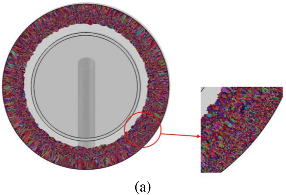

Figure 4: Thickness direction stratification pattern. (a) Microstructure of the center section of cylindrical Al-Cu alloy. (b) Schematic of casting thickness direction layering

Figure 5: Microstructure of different parts in the thickness direction of castings
The effects of different pouring temperatures on the grain size and SDAS of the casting were obtained. As shown in Fig. 6, the pouring temperatures are 700°C, 760°C, 820°C, 880°C, and 940°C. The data in the figure are the overall average grain size and SDAS of the casting.
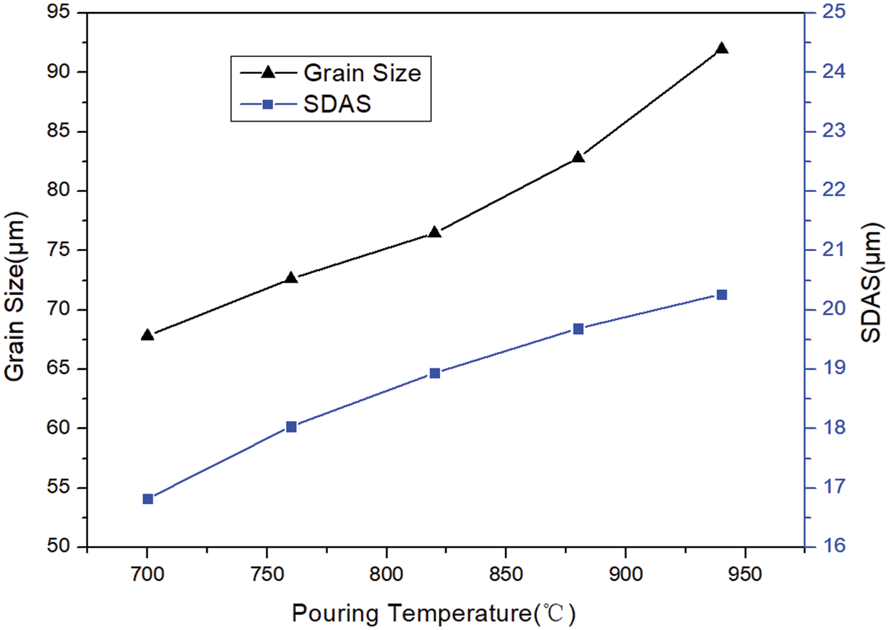
Figure 6: Effect of pouring temperature on the microstructure of castings
Fig. 6 shows that when the pouring temperature was 700°C, the grain size was 67 μm. The grain size increased with the pouring temperature. At 940°C, the grain size reached 91 μm. The variation of the SDAS also followed the same rule. When the pouring temperature was 700°C, the SDAS was 16 μm. When the pouring temperature increased to 940°C, the SDAS reached 20 μm. The increase in pouring temperature allow the melt to cool and solidify in the mold for a longer period of time, and the grains have more time to grow and therefore tend to form larger grains, affecting the performance of the casting.
Fig. 7 shows the effect of different mold preheating temperatures on the grain size and SDAS of the casting. The mold preheating temperatures are 25°C, 100°C, 200°C, and 300°C. The data in the figure are the overall average grain size and SDAS of the casting.

Figure 7: Effect of mold preheating temperature on the microstructure of castings
Fig. 7 shows that when the mold was not preheated, that is, the mold temperature was 25°C at room temperature, the grain size was 68 μm. The grain size also increased with the preheating temperature of the mold. When the preheating temperature was 300°C, the grain size reached 83 μm. The variation of the secondary dendritic arm spacing also followed the same rule. Without preheating, the secondary dendritic arm spacing was 17 μm. When the mold preheating temperature was 300°C, the SDAS reached 20 μm. The increase in mold preheating temperature results in slower cooling of the melt in the mold and longer solidification time. The grains have more time to grow and therefore tend to form larger grains, affecting the performance of the casting.
The effects of different pouring speeds on grain size and SDAS were simulated and analyzed, and the average grain size and SDAS of the castings were obtained at pouring speeds of 1, 2, 3, and 4 kg/s, as shown in Fig. 8.
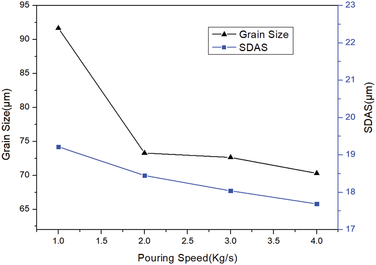
Figure 8: Effect of pouring speed on the microstructure of castings
The average grain size and SDAS of the casting decreased as the pouring speed increased. The pouring speed was increased from 1 to 4 kg/s, the grain size of the casting was increased from 91 μm drops to 70 μm, and the SDAS from 19 μm drops to 17 μm. In the casting process, the total amount of metal liquid poured into the casting process is unchanged, so the casting speed is small, the casting time will be longer, the whole process has been a high temperature of the metal liquid poured into the casting, the casting cooling process will be slower, and therefore the grain size will be smaller. The increase in pouring speed promoted the coarsening of the casting grain, affecting the performance of the casting.
The effects of different mold rotation speed on grain size and SDAS were simulated and analyzed, and the average grain size and SDAS of the castings were obtained at mold rotation speed of 500, 600, 700, 800, 900 and 1000 rpm, as shown in Fig. 9.

Figure 9: Effect of mold rotation speed on the microstructure of castings
The average grain size and SDAS of the casting decreased as the mold rotation speed increased. The mold rotation speed was increased from 500 to 1000 rpm, the grain size of the casting was increased from 70.2 μm drops to 64.5 μm, and the SDAS from 18.5 μm drops to 16.8 μm. The increase in mold rotation speed may lead to uneven distribution of solute elements in the melt, forming solute segregation. This segregation can provide the solute needed for grain growth and promote grain coarsening, affecting the performance of the casting.
4 Sensitivity Analysis of Hot Tearing in Centrifugal Casting
4.1 Overall Hot Tearing Sensitivity of Centrifugal Castings
In order to facilitate the thermal tearing sensitivity analysis, the optimized centrifugal casting parameters listed in Table 3 were used to obtain finer grain sizes according to the previous simulation results. After calculation by the RDG hot tearing criterion model, the obtained data included the shrinkage porosity, strain porosity, and porosity caused by the strain rates at various casting locations. To facilitate the observation of the distribution of porosity within the casting, two cross sections (a and b) of the cylindrical casting were selected for analysis, as shown in Fig. 9. Given the extremely small porosity caused by the strain rate and the small impact on the overall porosity distribution, only the shrinkage and deformation porosities of the casting were considered, and the total porosity was obtained by adding the shrinkage and deformation porosities in Fig. 10.


Figure 10: Cross section schematic of cylindrical castings
According to liquid phase feeding theory, the shrinkage pores during alloy solidification usually appear at the position where the alloy last solidifies. The liquid phase flow is more difficult because the solid skeleton is tighter at this time than at the early stage of solidification. Pores begin to form when the aluminum alloy liquid cannot be fed freely.
According to Figs. 11a and 12a, the areas with a large shrinkage porosity in the casting are mainly concentrated in the middle of the cylinder, and the shrinkage porosity in the inner side of the casting is larger than that in the outer side, with the maximum value exceeding 0.02. According to the physical model of the mold, the porosity is high near the pouring port of the mold where the temperature is high, so the solidification time of the molten metal is the longest, resulting in high shrinkage porosity.
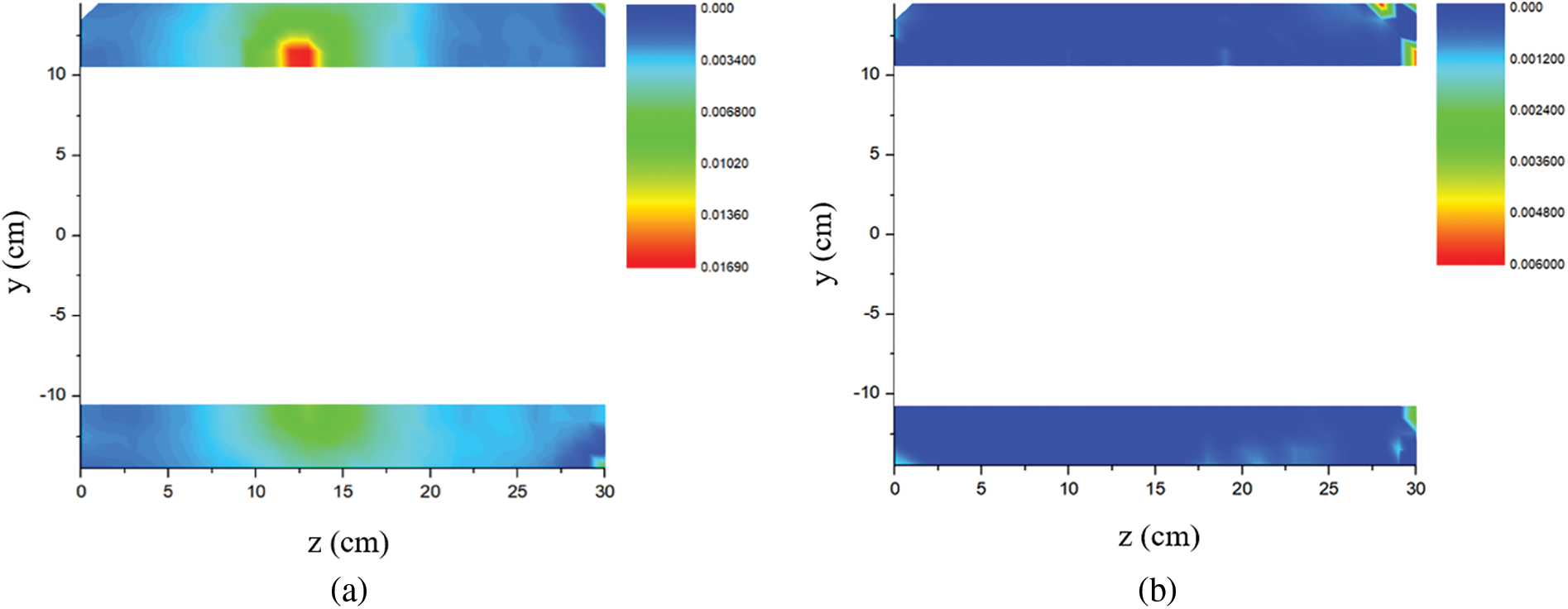
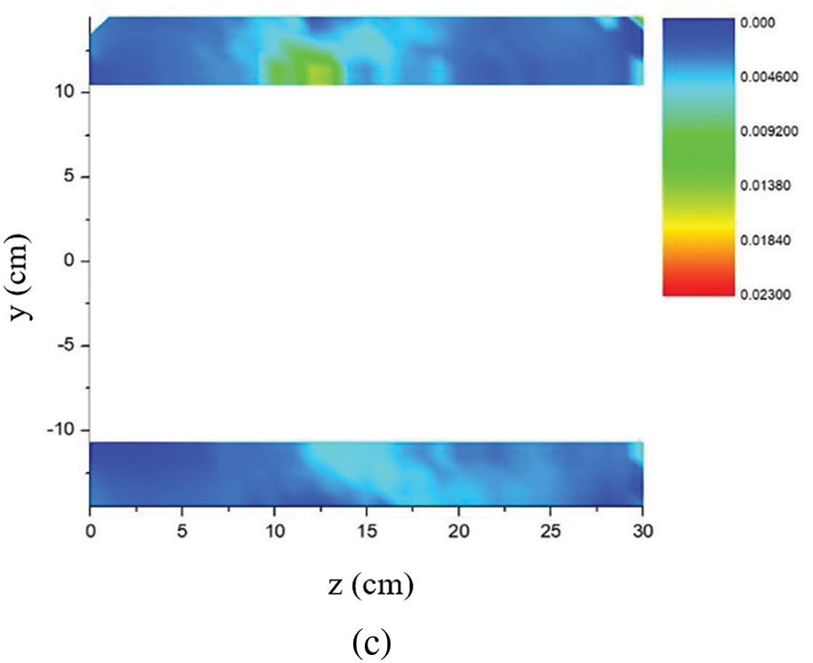
Figure 11: Distribution of porosity in section a. (a) Shrinkage porosity

Figure 12: Distribution of porosity in section b. (a) Shrinkage porosity
Figs. 11b and 12b show the distribution of the deformation porosity of cylindrical castings. The deformation porosity at the bottom of the casting is the largest, indicating that the bottom part bears greater stress than the other parts. However, the maximum porosity is approximately 0.006, which is far lower than the shrinkage porosity. Meanwhile, the distribution of the total porosity is basically the same as that of the shrinkage porosity, proving that the hot tearing of cylindrical castings is mainly caused by the feeding of the liquid phase.
An analysis was performed on the hot tearing sensitivity along the longitudinal section of the casting (as shown in Fig. 12). Fig. 13 shows the distribution of the total porosity in the longitudinal section of the casting. The total porosity in the middle of the casting is higher than that at both side-ends of the casting, and the distribution difference is significant. The total porosity on the inner side of the cylindrical section is higher than that on the outer side, with the highest point reaching approximately 0.02, indicating a strong sensitivity to hot tearing in the middle of the casting. The total porosity of the sections at the front and rear side-ends of the casting is relatively small, and no significant difference exists in the distribution of porosity at each point inside the section in Fig. 14.

Figure 13: Schematic of the longitudinal section of cylindrical castings

Figure 14: Distribution diagram of total porosity of circular cross-section of castings. (a) Total porosity at a cross section 5 cm away from the front side-end of the casting. (b) Total porosity at a cross section 15 cm from the front side-end of the casting. (c) Total porosity at the cross section 25 cm from the front side-end of the casting
4.2 Impact of Casting Conditions on Hot Crack Sensitivity
To study the effect of different centrifugal speeds on the hot tearing of castings while maintaining the consistency of other operating parameters (pouring temperature 760°C, mold preheating temperature 100°C, pouring speed 3 kg/s), different centrifugal speeds (500, 600, 750, 1000, and 1250 rpm) were selected to compare the occurrence of hot tearing using the improved RDG criterion prediction model. The variation curves of maximum porosity of castings with centrifugal speed were obtained as shown in Fig. 14.
When the centrifugal speed increased from 500 to 1250 rpm, the maximum porosity of the casting exhibited a downward trend in Fig. 15. When the rotational speed was 500 rpm, the hot tearing tendency was the highest, and the maximum porosity of the casting was 0.849. During centrifugal casting, the significant reduction in the tendency to thermal cracking can be attributed to the increase in centrifugal speed. As the centrifugal speed increases, the centrifugal force on the melt increases accordingly, which greatly improves the flow behavior of the melt, allowing it to fill the complexes and small voids of the mold more adequately, thus enhancing the melt’s ability to compensate for shrinkage. This excellent shrinkage compensation reduces the risk of thermal cracking due to inhomogeneous shrinkage, which in turn reduces the tendency of the alloy to crack.

Figure 15: Effect of centrifugal speed on the maximum porosity
To study the effect of different pouring temperatures on the hot tearing of castings, different pouring temperatures (700°C, 730°C, 760°C, 790°C, and 820°C) were selected, and other operating conditions parameters were kept consistent (centrifugal rotation speed 1000 rpm, mold preheating temperature 100°C, pouring speed 3 kg/s). The variation curve of the maximum porosity of castings with the pouring temperature was obtained as shown in Fig. 16. When the pouring temperature increased from 700°C to 760°C, the maximum porosity of the casting also maintained a downward trend. This may be due to the fact that, within a certain temperature range, the increase in pouring temperature helps to improve the fluidity and mold filling ability of the melt and reduces the formation of pores and shrinkage holes, thus reducing the porosity of the castings. When the pouring temperature was 760°C, the maximum porosity of the alloy was the lowest, reaching 0.212. This indicates that at this temperature, the melt’s mold filling properties and shrinkage capacity are optimized, contributing to the formation of a dense casting structure. When the pouring temperature rose to 820°C, the maximum porosity rose to 0.786, posing a significant hot tearing risk. This may be due to the increased superheating of the melt caused by the excessively high pouring temperature, which leads to an increased shrinkage of the melt during solidification, along with a decrease in the ability to make up for the shrinkage, which leads to the formation of more air holes and thermal cracks.

Figure 16: Changing rule of maximum porosity with pouring temperature
Fig. 17 shows the variation trend of the maximum porosity of the casting with the preheating temperature of the mold when other operating conditions are the same (centrifugal speed 1000 rpm, pouring temperature 760°C, and pouring speed 3 kg/s). The figure shows that the overall maximum porosity of the casting shows a downward trend with the increasing preheating temperature. When the preheating temperature was 300°C, the maximum porosity was 0.039, indicating that the hot tearing tendency was low.

Figure 17: Changing rule of the maximum porosity with preheating temperature of the mold
Mold preheating can reduce the temperature gradient of casting cooling, and an appropriate preheating temperature can reduce the generation of various defects during alloy solidification. However, model preheating can also decrease the solidification speed of the casting and reduces productivity. Therefore, the hot tearing tendency must be predicted under different working conditions through defect prediction models to determine suitable production conditions.
Fig. 18 shows that by using a mathematical model of microstructure evolution, the grain sizes of castings under different conditions can be obtained and compared with the obtained maximum porosity. The results show that the hot tearing tendency decreases with grain refinement, so the smaller the grain size is, the better the plasticity of the alloy and the lower the hot tearing sensitivity is. Considering that the increase in centrifugal speed will lead to the refinement of the alloy microstructure, this result further demonstrates the relationship between the hot tearing sensitivity and the centrifugal speed in Fig. 9.
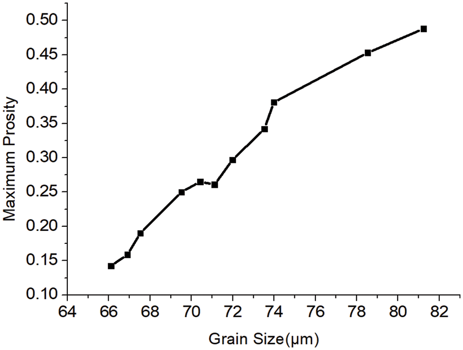
Figure 18: Change of maximum porosity with grain size
In this study, a microstructure evolution model and an improved RDG criterion mathematical model for centrifugal casting were established, and numerical simulation analysis was conducted for the centrifugal casting process of cylindrical Al-Cu alloy castings. The effects of the centrifugal casting process parameters on the microstructure and hot tearing sensitivity of castings were analyzed, and the following conclusions were obtained:
(1) Centrifugal casting conditions have a significant impact on the casting microstructure of Al-Cu alloy. Increasing the casting and preheating temperatures will lead to the coarsening of the casting microstructure, increasing the grain size and the SDAS. The increase of the pouring and centrifugal speeds has a significant effect on the decrease of the average grain size and SDAS of the casting and promotes the flow of the alloy liquid, which is conducive to the integrity of the mold filling.
(2) According to the improved RDG criterion model, the overall distribution of the hot tearing sensitivity of castings was analyzed. The results reveal that the porosity in the middle region of the casting was large, and hot tearing defects were prone to occur. The tendency of hot tearing in the inner side of the casting was greater than that in the outer side.
(3) The simulation results show that the hot tearing of alloy castings was mainly caused by liquid phase feeding. Different pouring conditions will have different effects on the distribution of porosity in castings.
(4) Within the range of parameters studied, the maximum porosity of castings first decreases and then increases with the increase of pouring temperature, and the minimum porosity occurs at the pouring temperature of 760°C.
(5) Increasing the preheating temperature of the mold will reduce the risk of hot tearing, with a maximum porosity of only 0.039 at a preheating temperature of 300°C. The refinement of grain size can reduce the risk of hot tearing, which is one of the reasons why increasing the centrifugal speed reduces the maximum porosity.
Acknowledgement: The authors would like to thank all the team members who participated in this study for their help and support. The authors would also like to thank their family and friends for their encouragement, who accompanied the authors through the hardships and challenges of the study. In addition, the authors would like to express their gratitude for the advice of the anonymous reviewers and editors, whose guidance made it possible to improve this study.
Funding Statement: The authors received no specific funding for this study.
Author Contributions: Xueli He: Methodology, Software, Validation, Formal analysis, Investigation, Writing—review &editing. Shengkun Lv: Methodology, Writing—original draft, Data curation, Visualization. Ruifeng Dou: Conceptualization, Methodology Validation, Resources, Supervision, Funding acquisition. Yanying Zhang: Methodology, Validation, Formal analysis. Junsheng Wang: Methodology Validation, Formal analysis. Xunliang Liu: Conceptualization, Project administration. Zhi Wen: Conceptualization, Supervision. All authors reviewed the results and approved the final version of the manuscript.
Availability of Data and Materials: The data that support the findings of this study are available from the corresponding author, Ruifeng Dou, upon reasonable request.
Ethics Approval: This study did not involve human or animal subjects. Therefore, ethical approval from an institutional review board or ethics committee was not required. The research adhered to the general ethical principles of scientific integrity and did not involve any experimental procedures that require ethical oversight.
Conflicts of Interest: The authors declare that they have no conflicts of interest to report regarding the present study.
References
1. R. M. Su, Y. X. Jia, J. Xiao, G. L. Li, Y. D. Qu and R. D. Li, “Effect of secondary aging on microstructure and properties of cast Al-Cu-Mg alloy,” China Foundry, vol. 20, no. 1, pp. 71–77, Jan. 2023. doi: 10.1007/s41230-023-1049-2. [Google Scholar] [CrossRef]
2. Z. Q. Mei et al., “Effect of rare-earth yttrium on structure and mechanical properties of as-cast Al-Cu-Mg-Ag alloy,” (in ChineseLight Alloy Fabrication Technol., vol. 49, no. 5, pp. 15–19, May 2021. doi: 10.13979/j.1007-7235.2021.05.003. [Google Scholar] [CrossRef]
3. P. G. Mukunda, R. A. Shailesh, and S. S. Rao, “Influence of rotational speed of centrifugal casting process on appearance, microstructure and sliding wear behavior of Al-2Si cast alloy,” Met. Mater. Int., vol. 16, no. 1, pp. 137–143, Feb. 2010. doi: 10.1007/s12540-010-0137-1. [Google Scholar] [CrossRef]
4. Z. G. Ding et al., “Effects of Cu content on microstructure and mechanical properties of rheo-diecasting Al-6Zn-2Mg-xCu alloys,” China Foundry, vol. 19, no. 4, pp. 321–326, Jul. 2022. doi: 10.1007/s41230-022-1138-7. [Google Scholar] [CrossRef]
5. J. Mi, R. A. Harding, and J. Campbell, “Effects of the entrained surface film on the reliability of castings,” Metall. Mat. Trans. A, vol. 35, no. 9, pp. 2893–2902, Apr. 2004. doi: 10.1007/s11661-004-0237-y. [Google Scholar] [CrossRef]
6. J. Sun, C. F. Xie, L. J. Sun, Y. B. Ma, and C. S. Mu, “Analysis and research on defects in centrifugal casting,” (in ChineseFoundry Equipment and Technology, vol. 209, no. 2, pp. 30–31, Apr. 2018. doi: 10.16666/j.cnki.issn1004-6178.2018.02.009. [Google Scholar] [CrossRef]
7. G. K. Sigworth, “Hot tearing of metals,” AFS Trans., vol. 155, pp. 1053–1063, 1996. [Google Scholar]
8. A. R. E. Singer and S. A. Cottrell, “Properties of the Al-Si alloys at temperatures in the region of the solidus,” J. Inst. Metals, vol. 73, pp. 33–54, 1996. [Google Scholar]
9. R. Dodd, “Hot tearing of cstings—A review of the literature,” Foundry Trade J., vol. 101, no. 1, pp. 321–331, 1956. [Google Scholar]
10. S. M. Xing and B. W. Zhao, “Study on hot cracking sensitivity of ZL205A produced by melted metal die forging,” (in ChineseJ. Changzhou Univ. (Nat. Sci. Ed.), vol. 33, no. 5, pp. 8–14, Sep. 2021. doi: 10.3969/j.issn.2095-0411.2021.05.001. [Google Scholar] [CrossRef]
11. H. Ding, H. Z. Fu, S. Z. Luo, Z. Y. Liu, and K. F. Zhang, “Effect of chemical composition on the tendency to thermal cracking of directionally solidified Al-Cu alloys,” (in ChineseActa Metallurgica Sinica, vol. 31, no. 8, pp. 376–380, 1995. [Google Scholar]
12. H. Bishop and C. Ackerlind, “Metallurgy and mechanics of hot tearing,” AFS Trans., vol. 60, no. 1, pp. 818–833, 1952. [Google Scholar]
13. N. Hatami, R. Babaei, M. Dadashzadeh, and P. Davami, “Modeling of hot tearing formation during solidification,” Mat. Process. Technol., vol. 205, no. 1, pp. 506–513, Nov. 2007. doi: 10.1016/j.jmatprotec.2007.11.260. [Google Scholar] [CrossRef]
14. M. M. Hamdi, “A two-phase model addressing hot tearing formation during aluminum direct chill casting,” Metallurgical Mater. Trans. A, vol. 37, no. 10, pp. 3069–3083, Oct. 2006. doi: 10.1007/s11661-006-0188-6. [Google Scholar] [CrossRef]
15. V. Mathier, “Two-phase modeling of hot tearing in aluminum alloys using a semi-couple approach,” Model. Simul. Mater. Sci. Eng., vol. 15, no. 2, pp. 121–134, 2007. doi: 10.1088/0965-0393/15/2/008. [Google Scholar] [CrossRef]
16. H. S. Carslaw and J. C. Jaeger, “Conduction of heat in solids and heat conduction,” Phys. Today, vol. 1, no. 7, p. 24, Jan. 2009. doi: 10.1063/1.3066187. [Google Scholar] [CrossRef]
17. D. G. Eskin, Suyitno, and L. Katgerman, “Mechanical properties in the semi-solid state and hot tearing of aluminum alloys,” Prog. Mater. Sci., vol. 49, no. 5, pp. 629–711, Jun. 2004. doi: 10.1016/S0079-6425(03)00037-9. [Google Scholar] [CrossRef]
18. T. Clyne and G. Davies, “Comparison between experimental data and theoretical predictions relating to dependence of solidification cracking on composition,” Solidification Cast. Metals, vol. 1977, no. 1, pp. 275–278, Jul. 1979. [Google Scholar]
19. C. A. Monroe, D. A. Gorsky, K. R. Huff, and R. V. Grandhi, “Improving the directional solidification of complex geometries through taper addition,” Inst. Phys. Conf. Series Mat. Sci. Eng., vol. 33, no. 1, pp. 23–27, Jan. 2014. doi: 10.1088/1757-899X/33/1/012004. [Google Scholar] [CrossRef]
20. I. Khaled, “Prediction of shrinkage porosity in Ti-46Al-8Nb tilt-casting using the niyama criterion function,” Int. J. Metalcasting, vol. 4, no. 7, pp. 35–42, Jan. 2012. doi: 10.1007/BF03355562. [Google Scholar] [CrossRef]
21. T. W. Clyne and W. Kurz, “Solute redistribution during solidification with rapid solit-state diffusion,” Metallurgical Trans. A, vol. 12, no. 6, pp. 965–971, 1981. doi: 10.1007/BF02643477. [Google Scholar] [CrossRef]
22. K. W. Suyitno and L. Kategerman, “Integrated approach for prediction of hot tearing,” Metallurgical and Meter Trans. A, vol. 40, no. 10, pp. 2388–2400, Oct. 2009. doi: 10.1007/s11661-009-9941-y. [Google Scholar] [CrossRef]
23. M. Rappaz, J. M. Drezet, and M. Gremaud, “A new hot-tearing criterion,” Metallurgical Mater. Trans. A, vol. 30, no. 2, pp. 449–445, Feb. 1999. doi: 10.1007/s11661-999-0334-z. [Google Scholar] [CrossRef]
24. J. C. Borland, “Fundamentals of solidification cracking in welds,” Weld. Metal Fabrication, vol. 47, no. 1, pp. 19–29, 1979. [Google Scholar]
25. W. S. Li et al., “Determination of thermophysical parameters of large steel castings and their application in solidification simulation,” (in ChineseFoundry Technol., vol. 31, no. 11, pp. 1393–1395, Nov. 2010. [Google Scholar]
26. Z. Jun et al., “Elimination of misrun and gas hole defects of investment casting TiAl alloy turbocharger based on numerical simulation and experimental study,” (in ChineseChina Foundry, vol. 17, no. 1, pp. 29–34, Jan. 2020. doi: 10.1007/s41230-020-8151-5. [Google Scholar] [CrossRef]
27. Y. Z. Xu, Z. S. Du, and X. D. Song, “Numerical simulation of flow field and temperature field in centrifugal casting solidification process,” (in ChineseCasting Forging Weld., vol. 41, no. 21, pp. 40–43, Nov. 2012. [Google Scholar]
28. S. L. Lu, F. R. Xiao, S. J. Zhang, Y. W. Mao, and B. Liao, “Simulation study on the centrifugal casting wet-type cylinder liner based on ProCAST,” Appl. Therm. Eng., vol. 73, no. 1, pp. 512–521, Dec. 2014. doi: 10.1016/j.applthermaleng.2014.07.073. [Google Scholar] [CrossRef]
29. A. J. Kumar, K. Krishnakumar, and S. Savithri, “Computer simulation of centrifugal casting process using FLOW-3D,” Mater. Sci. Forum, vol. 4105, no. 830–831, pp. 53–56, Oct. 2015. doi: 10.4028/www.scientific.net/MSF.830-831.53. [Google Scholar] [CrossRef]
30. M. Flemings and R. Cahn, “Organization and trends in materials science and engineering education in the US and Europe,” Acta Mater., vol. 48, no. 1, pp. 371–383, Jun. 2000. doi: 10.1016/S1359-6454(99)00305-5. [Google Scholar] [CrossRef]
31. S. K. Lv, R. F. Dou, B. Yu, J. S. Wang, X. L. Liu and Z. Wen, “Experimental and numerical studies on the influence of centrifugal casting parameters on the solidification structure of Al-Cu alloy,” Mater. Res. Express, vol. 9, no. 10, pp. 106506, Oct. 2022. doi: 10.1088/2053-1591/AC94B8. [Google Scholar] [CrossRef]
32. B. Wang and J. S. Wang, “Research progress on defect predictions during solidification of aluminum alloys,” (in ChineseAeronaut. Manuf. Technol., vol. 65, no. 5, pp. 76–86, Apr. 2022. doi: 10.16080/j.1671-833x.2022.05.076. [Google Scholar] [CrossRef]
33. M. Seredyński and J. Banaszek, “Numerical study of crystal growth kinetics influence on prediction of different dendritic zones and macro-segregation in binary alloy solidification,” Int. J. Numer. Methods Heat Fluid Flow, vol. 28, no. 4, pp. 2363–2377, May 2019. doi: 10.1108/HFF-11-2018-0712. [Google Scholar] [CrossRef]
34. R. F. Dou and A. B. Phillion, “Application of a pore fraction hot tearing model to directionally solidified and direct chill cast aluminum alloys,” Metall. Mat. Trans., vol. 47, no. 8, pp. 4217–4225, Aug. 2016. doi: 10.1007/s11661-016-3590-8. [Google Scholar] [CrossRef]
35. B. Yu, R. F. Dou, Y. F. Wang, J. S. Wang, X. L. Liu and Z. Wen, “Mathematical and experimental study on hot tearing of AA5182 aluminum alloy,” Int. J. Metalcasting, vol. 17, no. 2, pp. 1201–1216, Aug. 2022. doi: 10.1007/S40962-022-00848-Z. [Google Scholar] [CrossRef]
36. S. L. Lu, L. Cao, Z. H. Guo, X. Z. Zhang, R. H. Zhang and H. Y. Li, “Simulation of mold filling flow in horizontal centrifugal casting of cylindrical parts based on ProCAST,” (in ChineseFoundry, vol. 68, no. 9, pp. 1036–1041, Sep. 2019. [Google Scholar]
37. Q. Dong, Z. W. Yin, H. L. Li, G. Y. Gao, and Y. Mao, “Simulation study on filling and solidification of horizontal centrifugal casting babbitt lining of bimetallic bearing,” Int. J. Metalcasting, vol. 15, no. 1, pp. 1–11, Feb. 2020. doi: 10.1007/s40962-020-00429-y. [Google Scholar] [CrossRef]
38. Y. Li, B. S. Zhang, X. M. Qian, X. L. Li, Z. D. Wang and L. Z. Meng, “Microstructure and mechanical properties of 7055 aluminum alloy by vacuum centrifugal casting,” (in ChineseChinese J. Nonferrous Metals, vol. 32, no. 7, pp. 1863–1871, Sep. 2022. doi: 10.11817/j.ysxb.1004.0609.2021-4204. [Google Scholar] [CrossRef]
Cite This Article
 Copyright © 2024 The Author(s). Published by Tech Science Press.
This work is licensed under a Creative Commons Attribution 4.0 International License , which permits unrestricted use, distribution, and reproduction in any medium, provided the original work is properly cited.
 Downloads
 Citation Tools