
 Submit a Paper
 Propose a Special lssue
 Open Access
ARTICLE

A Novel Anti-Collision Algorithm for Large Scale of UHF RFID Tags Access Systems
1 School of Information and Communication Engineering/Yibin Institute, University of Electronic Science and Technology of China, Chengdu, 611731, China
2 Department of IoT Technology Research, China Mobile Research Institute, Beijing, 100053, China
3 The 10th Research Institute of China Electronics Technology Group Corporation, Chengdu, 611731, China
4 College of Information and Communication, National University of Defense Technology, Wuhan, 430019, China
* Corresponding Author: Jian Li. Email:
Computers, Materials & Continua 2024, 80(1), 897-912. https://doi.org/10.32604/cmc.2024.050000
Received 24 January 2024; Accepted 09 April 2024; Issue published 18 July 2024
 View Full Text
 Download PDF
Abstract
When the radio frequency identification (RFID) system inventories multiple tags, the recognition rate will be seriously affected due to collisions. Based on the existing dynamic frame slotted Aloha (DFSA) algorithm, a sub-frame observation and cyclic redundancy check (CRC) grouping combined dynamic framed slotted Aloha (SUBF-CGDFSA) algorithm is proposed. The algorithm combines the precise estimation method of the quantity of large-scale tags, the large-scale tags grouping mechanism based on CRC pseudo-random characteristics, and the Aloha anti-collision optimization mechanism based on sub-frame observation. By grouping tags and sequentially identifying them within subframes, it accurately estimates the number of remaining tags and optimizes frame length accordingly to improve efficiency in large-scale RFID systems. Simulation outcomes demonstrate that this proposed algorithm can effectively break through the system throughput bottleneck of 36.8%, which is up to 30% higher than the existing DFSA standard scheme, and has more significant advantages, which is suitable for application in large-scale RFID tags scenarios.Keywords
Passive ultra-high frequency (UHF) RFID [1–3] has gained widespread use in the industrial sector due to its extensive communication range, rapid identification speed, strong reliability, ample storage capacity, and other benefits. In the process of transmission between tags and reader, interference and collision between data will be caused due to the sharing of the same wireless channel [4–6]. Currently, anti-collision algorithms utilizing RFID may be roughly divided into two categories: deterministic algorithm based on tree [7–10] and random algorithm based on Aloha class [11–15]. The tree-based anti-collision algorithm is a deterministic algorithm. Multiple tags are constantly grouped in the recognition process until there is only one tag in the group, at which point the reader can successfully identify it [16–17]. Random algorithms based on the Aloha class mainly include the pure Aloha algorithm (PA), slotted Aloha algorithm (SA), framed slotted Aloha algorithm (FSA), DFSA [18–20] and various enhanced algorithms [21–23].
The advantages of Aloha algorithms are low cost, easy implementation, and low hardware requirements for readers. This type of algorithm does not require the detection of specific collision locations, making it well-suited for application in UHF RFID systems. Chen et al. utilized the maximum a posteriori probability decision algorithm to estimate quantity of tags and proposed an enhanced Aloha algorithm to enhance the efficiency of RFID systems [24]. Zhang et al. put forward an Aloha algorithm for grouping adaptive time-slot allocation. The main concept is to pre-scan the time slots selected by tags so that they can adaptively choose and allocate time slots, thus avoiding extensive collision and idle time slots [25]. An anti-collision algorithm named Grouped Dynamic Frame Slotted Aloha (GDFSA) was also introduced in which the estimated tag number is first determined, followed by grouping and dynamic frame slot strategies to identify tags [26]. Chen et al. estimated unrecognized tags by observing collision and idle slots in subframes, dynamically adjusting the frame length range and proposing a dynamic frame slot Aloha algorithm based on a subframe observation mechanism with system throughput near optimal at 0.361 [27]. Mustapha et al. suggested an Aloha algorithm based on Bayesian tag estimation, which improved accuracy while maintaining system throughput optimality [28]. To improve identification performance in dense tag situations, Bai et al. modified tag set grouping using fuzzy C values and presented an anti-collision Aloha method based on EPC grouping [29]. Zahran et al. brought forth an Aloha algorithm for optimal frame length allocation adopting multi-factor estimation to dynamically adjust frame length gradually reducing invalid time slots [30]. The results indicated that the system efficiency could still be maintained even when there is large-scale access to tags.
In this paper, the SUBF-CGDFSA algorithm is proposed. In accordance with both experimental and theoretical analysis of the current anti-collision algorithm, this algorithm takes the grouping mechanism as the starting point and combines the sub-frame observation mechanism with the accurate tags number estimation method. On the basis of them, this paper optimizes and improves them. The large-scale tags grouping mechanism is used first, and then the sub-frame based DFSA (SUBF-DFSA) algorithm is used to identify intra-group tags. In contrast to current anti-collision algorithms, the suggested approach exhibits enhanced flexibility in recognizing a substantial quantity of tags. It effectively maintains high throughput, significantly improves slot efficiency, and conserves a substantial amount of system resources.
2 Preliminaries: Tags Estimation, Grouping Rules and Sub-Frame Observation Mechanism
An RFID reader typically deploys a large quantity of tags, with all tags sharing the same communication channel. This often leads to tag collision, resulting in increased collision time slots. The efficient identification of a large quantity of tags poses a significant challenge in RFID systems. Performance indicators are required in order to assess multi-tag anti-collision algorithms’ macroscopic performance. The ratio of successful time slots needed by a reader to identify every tag in its working domain to the total quantity of time slots, also referred to as throughput, defines the system efficiency of an anti-collision algorithm in RFID systems. The system efficiency
The more time slots the anti-collision algorithm utilizes, the lower the system efficiency it can achieve. Thus, system efficiency is one of the most crucial measures to assess the efficacy of RFID anti-collision algorithms.
When optimizing the system efficiency, it is essential to accurately estimate quantity of tags in the application scene and consider the algorithm complexity. This paper conducts research on system recognition efficiency based on the Schoute tags estimation method and the Vogt tags estimation method.
The Schoute tags estimation method is based on the Poisson estimation technique. The Poisson tags estimation function is proposed in accordance with the posterior probability of
where
The Vogt algorithm is utilized to estimate the quantity of remaining tags in accordance with the tag recognition status from the previous frame. This algorithm is grounded in the Chebyshev inequality principle, which states that the results of random experiments on any random variable will eventually converge towards the expected value. In other words, the quantity of tags
The system’s frame length is represented as
Therefore, the expected value
Grouping rules are suggested to guarantee a high throughput rate while handling a large quantity of tags. This will enable the reader to maintain efficiency under such circumstances. If the quantity of tags is small, grouping is not necessary. However, if the quantity of tags is too large, it is advisable to arrange the tags based on the estimated range. This significantly reduces tag collisions. The electronic tag is the data carrier of the identification object, storing the information of the identification object and the tag, and generating a CRC code according to the data sequence after the data is written to the tag, which is used to verify the sequence in data communication. Moreover, CRC check codes have good pseudo-random characteristics, and the generated low-level CRC check codes are close to uniform distribution. The group identification algorithm uses the CRC codes of tags as the basis for grouping. In the algorithm, the generated CRC codes are used to generate a lower CRC code value as the group number of each tag.
In the existing RFID standards, 16-bit CRC code is generally used as the verification code, so the 16-bit CRC is discussed as an example. For example, after a tag receives a request to start recognition, it extracts its own 16-bit CRC code value, and it divided by the generator polynomial
According to the group processing of identification tags in the scenario, the algorithm maintains a high and stable throughput for each quantity of tags. The quantity of groups is determined in accordance with the quantity of tags, and it is significant to establish the critical value of tags for switching between the number of groups. Based on different sets of regulations, various critical values for tags can be established.
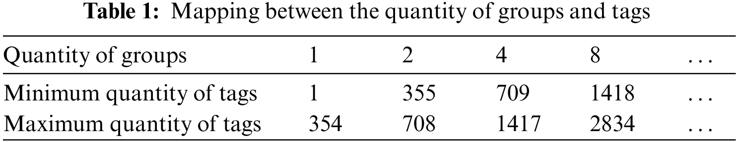
2.2.1 Critical Value to Determine Scheme Ⅰ
The critical value for grouping tags is chosen in accordance with the quantity of tags and the reading throughput, taking into account varying numbers of groups. For instance, assuming
The frame length is fixed at a value of
In formula (9),
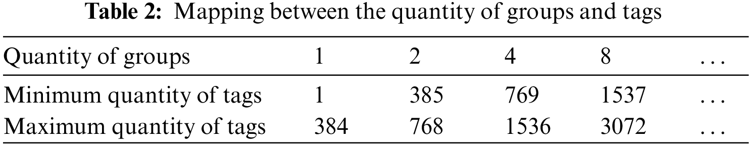
2.2.2 Critical Value to Determine Scheme Ⅱ
Maximum throughput in the traditional DFSA method is reached when the quantity of tags is equal to the original frame length. For an original frame length of 256, the generated CRC check code consists of 1 bit and is divided into two groups. The theoretical maximum throughput is achieved when there are 2 * 256 = 512 tags present, resulting in a generated CRC check code of 2 bits divided into four groups. This pattern continues, with maximum throughput being achieved at 4 * 256 = 1024 tags and so on.
The quantity of tags corresponding to the optimal throughput of adjacent grouping schemes is determined, and the median value of the two is identified as the critical value. For instance, if there are 256 * 21 = 512 tags for the two groups and 256 * 22 = 1024 tags for the four groups, the critical value would be the median of these two numbers, which is (512 + 1024)/2 = 768. Table 2 can then be filled in accordingly.
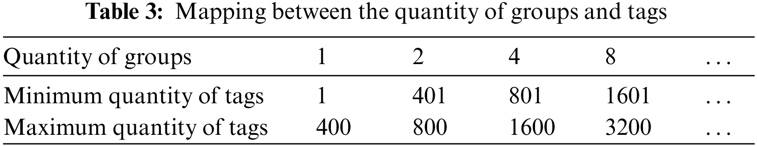
2.2.3 Critical Value to Determine Scheme III
When categorizing tags in the scene, the quantity of bits generated by different CRC check codes determines the quantity of groups. The simulation of throughput based on CRC check grouping combined with the traditional DFSA algorithm indicates that as the quantity of tags continues to increase, the system throughput will decrease. To ensure optimal grouping performance, with an initial frame length

Figure 1: Performance comparison of traditional DFSA in different grouping schemes
According to the simulation outcomes, the critical value of the number of tags for different grouping schemes is determined. This corresponds to the quantity of tags at the intersection point of the throughput rate of adjacent grouping schemes, and is recorded in Table 3.
At the onset of the initial RFID system identification and at the conclusion of each round of identification, an estimation is made regarding the number of tags that remain unidentified. Based on these predictive results, a determination is made as to whether it is necessary to group the tags. In cases where tags must be sorted into multiple groups for identification purposes, the reader employs an identification frame with the maximum quantity of time slots in order to identify tags. This approach allows for control over the quantity of tags in each group within a higher reading throughput range, thereby preventing significant tag collisions during identification. Consequently, these three strategies effectively maintain a high throughput rate for the system and reduce tag recognition time.
2.3 Sub-Frame Observation Mechanism
In order to simplify the tags number estimation algorithm, it is recommended to avoid using methods that require extensive computation. By doing this, we may increase the tags number estimate algorithm’s time efficiency and lower its computing complexity. The traditional DFSA algorithm estimates the quantity of unrecognized tags in accordance with the relationship between successful, collision, and idle slots in the entire frame, in order to adjust the size of the next frame length. However, if the frame length in the previous recognition cycle was not appropriate, it may negatively impact the next recognition cycle and significantly reduce system recognition efficiency. Therefore, a new mechanism will be introduced to estimate the quantity of unrecognized tags using only a portion of the current frame, namely a subframe.
The algorithm calculates the estimated quantity of tags to be identified in accordance with the statistics of idle, successful, and collision slots observed in subframes, as well as the relationship between subframes and current frames. Assuming that
where
When the value of
The frame length is modified based on the above-mentioned tag estimate findings, with the subframe
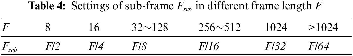
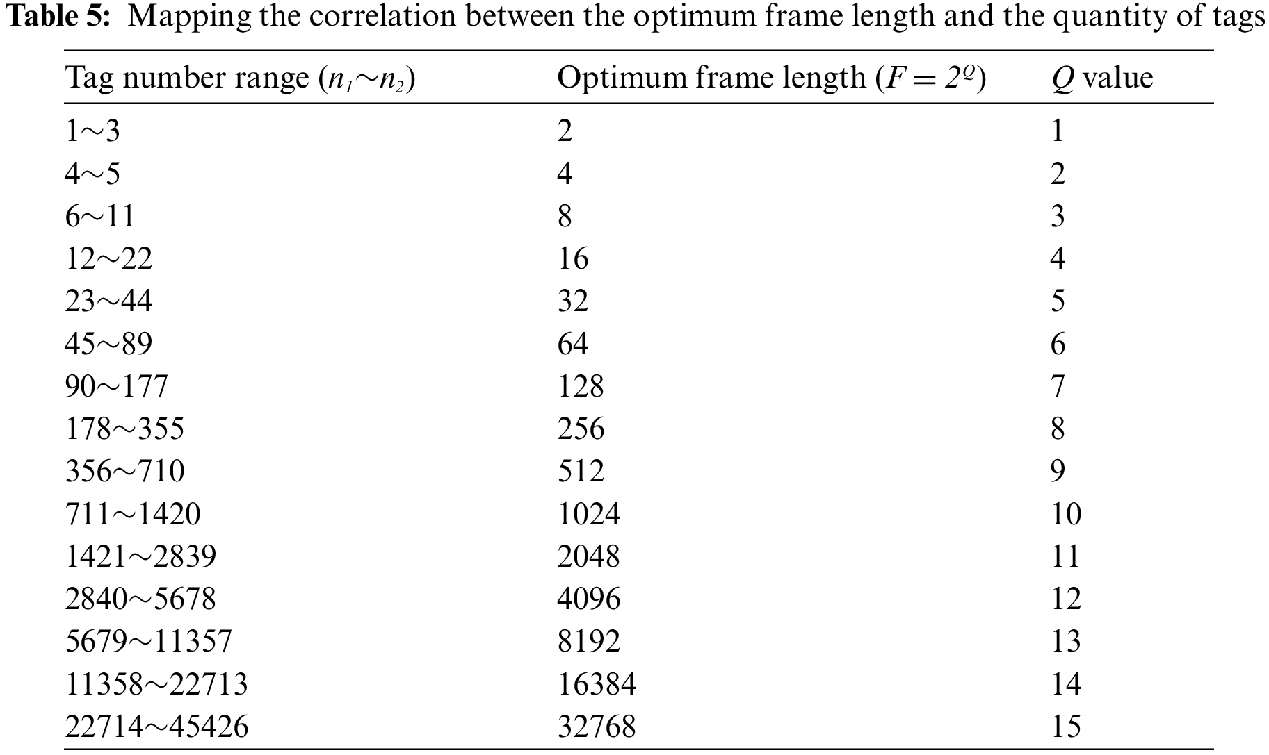
In accordance with EPC global C1 Gen2 standard, frame length
Given a tag number
where
In the actual RFID system, tag number
where
3 Proposed SUBF-CGDFSA Description
Using the large-scale tags grouping technique is the initial step if a large quantity of tags needs to be identified in the scene. Subsequently, the SUBF-DFSA algorithm is employed to identify intra-group tags. Combined with the tags number estimation method, tags grouping method and sub-frame observation mechanism, this paper proposes a novel Aloha algorithm, namely SUBF-CGDFSA algorithm. The SUBF-CGDFSA algorithm flow is shown in Fig. 2.

Figure 2: Flow chart of SUBF-CGDFSA algorithm
In this algorithm, the frame length is adjusted in accordance with the statistical results of subframe
where
Since the frame length is constantly changing, so is the sub-frame
where
The SUBF-CGDFSA algorithm flow is as follows:
Step 1: The reader sets the frame length
Step 2: In accordance with the quantity of tags to be identified, the reader sends grouping instructions to judge the interval where the quantity of tags is located. If the quantity of tags does not fall in the first interval, the group operation is performed, otherwise, the fourth step is entered;
Step 3: When the tag obtains the instruction from the reader, it also acquires the group number
Step 4: The reader transmits query commands to tags within the operational domain, specifying frame length
Step 5: The tag response is received by the reader in each slot,
Step 6: The reader updates frame length
Step 7: According to the formula (19), the average tag number
Step 8: Verify if the stack is empty. If it is, the identification process concludes. This group identification is over, and the value of
Step 9: The label broadcast query command, which may result in slot conflicts, includes the initial frame length
Step 10: After reading a time slot, the reader calculates statistics
Step 11: After each round of recognition, it is essential to estimate the quantity of remaining unrecognized tags. If it is zero, the whole recognition process will be finished. Otherwise, the next round of recognition will be carried out.
Compared to the existing Aloha anti-collision algorithm, SUBF-CGDFSA algorithm has better stability. In addition, the determination of tag quantity and the establishment of frame length during the recognition process are accomplished through table lookup. This only requires a single judgment in each recognition cycle, with the evaluation process involving only addition, multiplication, and comparison operations, resulting in minimal complexity.
Using MATLAB simulation platform, according to ISO18000-6C (EPC C1G2) standard, all tag lengths are standardized to 128 bits. The initial frame length

Figure 3: Comparison of tags estimation results (a) estimated result of tags; (b) the error between the estimated and actual quantity of tags
The simulation results indicate that with the inventory times increasing, the quantity of tags to be identified in the scene gradually decreases. For this reason, the tags estimation results based on the above two tags estimation algorithms show that the tags estimation based on the Vogt algorithm is more accurate than the Schoute algorithm, especially in the initial inventory.
Based on sub-frame observation, the initial frame length is adjusted and the quantity of tags in the collision time slot is processed. The SUBF-DFSA algorithm is employed for tags in the collision slots, and the Schoute and Vogt estimation method are utilized to estimate the remaining quantity of tags, which are then used as the initial frame length for the next frame. In our simulation, we set the initial frame length

Figure 4: Simulation of SUBF-DFSA algorithm based on two tags estimation methods (a)
Simulation outcomes indicate that the SUBF-DFSA anti-collision algorithm can break through the bottleneck of 36.8%. With the increase of the quantity of tags, the system throughput rate remains above 40% after stabilization. Significantly improve the recognition performance of the system. When the initial frame size is set to 32, 64, 128, and 256, the system recognition efficiency does not decrease. In addition, the frame length of the SUBF-DFSA algorithm is slightly adjusted to the integer power of 2, which conforms to the EPC global C1 Gen2 protocol standard.
According to the scheme to determine the tags grouping critical value obtained from the grouping theory analysis above, grouping scheme switching is carried out when the quantity of tags is in different intervals. The simulation results of SUBF-CGDFSA anti-collision algorithm were compared with the existing algorithms, such as SUBF-DFSA, GDFSA [26], traditional DFSA and FSA. Fig. 5 illustrates a comparison of the system efficiency for these various algorithms.
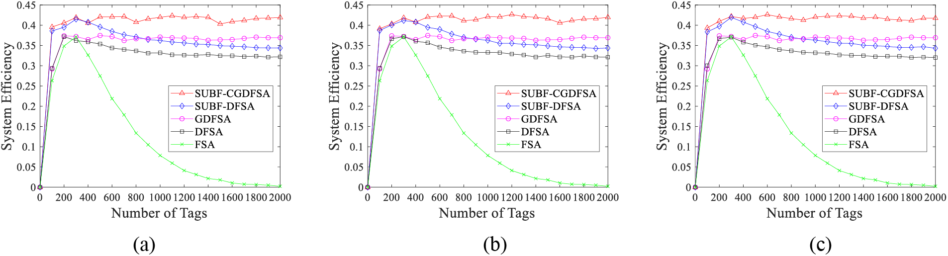
Figure 5: Comparison of system efficiency of different algorithms (a) critical value to determine scheme Ⅰ; (b) critical value to determine scheme Ⅱ; (c) critical value to determine scheme III
The simulation outcomes indicate that the system efficiency of SUBF-CGDFSA algorithm is almost unaffected by the number of tags. In large-scale tags scenarios, the three grouping schemes can all maintain high system efficiency and stable performance. For the actual large-scale tags access scenario, grouping mismatch will cause a series of problems. If there are too many groups, a large quantity of idle time slots will be produced within the group, leading to time slot waste and decreased algorithm performance. Conversely, if the quantity of groups is too small, frequent collisions will occur within the group. Even if the group is divided, desired system efficiency cannot be achieved and algorithm performance will deteriorate. Simulation results show that dynamic grouping based on the critical value obtained from theoretical analysis can flexibly avoid the above problems. The algorithm can achieve high throughput and maintain stability in each tag number interval. When compared to the method without grouping, the grouping algorithm performs noticeably better.
Taking the performance of traditional DFSA as the benchmark, the improvement of system efficiency of each algorithm compared with traditional DFSA algorithm was investigated. The outcomes of the simulation are depicted in Fig. 6.
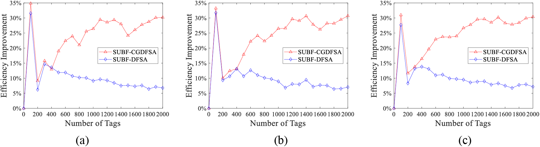
Figure 6: Comparison of performance improvement of each algorithm compared with traditional DFSA algorithm (a) critical value to determine scheme Ⅰ; (b) critical value to determine scheme Ⅱ; (c) critical value to determine scheme III
The simulation outcomes indicate that the performance of the SUBF-DFSA algorithm is remarkably enhanced compared with the traditional DFSA algorithm in large-scale tag scenarios. Furthermore, the SUBF-CGDFSA algorithm has further improved the throughput index under different grouping schemes. When the quantity of tags is low and frequent collision is absent, both algorithms perform similarly and demonstrate a substantial improvement in system efficiency compared to the traditional DFSA. However, when the quantity of tags exceeds 300, the throughput of the SUBF-DFSA algorithm can be increased by approximately 10%. Moreover, when there are more than 1200 tags, the throughput performance of the SUBF-CGDFSA algorithm consistently increases by over 30% after grouping using three distinct schemes. Specifically, with grouping scheme 3 for identifying 1500 tags, the maximum throughput rate can be increased by around 32%. As evident from these findings, as the quantity of tags increases, there is a more pronounced improvement in throughput, thus indicating its suitability for large-scale tag access systems.
In this paper, an innovative anti-collision algorithm named SUBF-CGDFSA for large scale of UHF RFID tags access systems is proposed. The large-scale tags grouping mechanism is first used to group tags, and the sub-frame observation mechanism is introduced in order to support massive tag identification scenarios. The intra-group identification is accomplished by estimating the number of tags in the subframe and optimizing the frame length settings through the preset configuration table, reducing system complexity. The results indicate that the novel RFID anti-collision algorithm proposed in this paper, namely SUBF-CGDFSA, can break through the bottleneck of 36.8% of the system throughput. With the increase in the quantity of tags, the system’s throughput rate remains stable at over 40%. At the same time, the algorithm is not affected by the initial frame length and exhibits excellent robustness. The proposed anti-collision algorithm has a broad application prospect in intelligent detection. Through reasonable selection and optimization algorithm, real-time perception of the surrounding environment and prediction of collision risk can be realized, enhancing the convenience of people’s daily lives and work. With the ongoing development of artificial intelligence technology, it is believed that the implementation of this anti-collision algorithm utilizing artificial intelligence will lead to significant breakthroughs and innovations in the field.
Acknowledgement: The authors would like to thank the editors and reviewers for their valuable work, as well as the supervisor and family for their valuable support during the research process.
Funding Statement: This work was supported in part by National Natural Science Foundation of China (U22B2004, 62371106), in part by the Joint Project of China Mobile Research Institute & X-NET (Project Number: 2022H002), in part by the Pre-Research Project (31513070501), in part by National Key R&D Program (2018AAA0103203), in part by Guangdong Provincial Research and Development Plan in Key Areas (2019B010141001), in part by Sichuan Provincial Science and Technology Planning Program of China (2022YFG0230, 2023YFG0040), in part by the Fundamental Enhancement Program Technology Area Fund (2021-JCJQ-JJ-0667), in part by the Joint Fund of ZF and Ministry of Education (8091B022126) and in part by Innovation Ability Construction Project for Sichuan Provincial Engineering Research Center of Communication Technology for Intelligent IoT (2303-510109-04-03-318020).
Author Contributions: The authors confirm contribution to the paper as follows: Jian Li: Investigation, Software, Methodology and Funding. Xu Zhang: Investigation, Writing-Original Draft, Writing-Review and Editing. Yi He and Haiwen Yi: Data Collection. Yulu Zhang, Yuan Li and ShuaiMa: Analysis and Interpretation of Results. Gui Li, Zhiyuan Zhao and Junyang Liu Resources and Validation. Junyang Liu and Guangjun Wen: Writing Review and Editing. All authors reviewed the results and approved the final version of the manuscript.
Availability of Data and Materials: The data that support the findings of this research are available from the corresponding author, Jian Li, upon reasonable request.
Conflicts of Interest: The authors declare that they have no conflicts of interest to report regarding the present research.
References
1. A. Lehto, J. Nummela, L. Ukkonen, L. Sydanheimo, and M. Kivikoski, “Passive UHF RFID in paper industry: Challenges, benefits and the application environment,” IEEE Trans. Autom. Sci. Eng., vol. 6, no. 1, pp. 66–79, Jan. 2009. doi: 10.1109/TASE.2008.2007269. [Google Scholar] [CrossRef]
2. K. Saarinen, T. Björninen, L. Ukkonen, and L. Frisk, “Reliability Analysis of RFID Tags in Changing Humid Environment,” IEEE Trans. Compon., Packag. Manufact. Technol., vol. 4, no. 1, pp. 77–85, Jan. 2014. doi: 10.1109/TCPMT.2013.2278182. [Google Scholar] [CrossRef]
3. P. Solic, Z. Blazevic, M. Skiljo, L. Patrono, R. Colella and J. J. P. C. Rodrigues “Gen2 RFID as IoT Enabler: Characterization and performance improvement,” IEEE Wirel. Commun., vol. 24, no. 3, pp. 33–39, Jun. 2017. doi: 10.1109/MWC.2017.1600431. [Google Scholar] [CrossRef]
4. W. Wang, Y. Zhang, Y. Sang, and S. Wang, “Analysis of anti-collision algorithms in RFID system,” in 2009 IEEE Int. Conf. Commun. Technol. Appl., Beijing, China, 2009, pp. 58–62. doi: 10.1109/ICCOMTA.2009.5349239. [Google Scholar] [CrossRef]
5. L. Zhu and T. S. P. Yum, “A critical survey and analysis of RFID anti-collision mechanisms,” IEEE Commun. Mag., vol. 49, no. 5, pp. 214–221, May 2011. doi: 10.1109/MCOM.2011.5762820. [Google Scholar] [CrossRef]
6. R. Jayadi, Y. Lai, and C. Lin, “Efficient time-oriented anti-collision protocol for RFID tag identification,” Comput. Commun., vol. 112, no. 3, pp. 141–153, Nov. 2017. doi: 10.1016/j.comcom.2017.08.016. [Google Scholar] [CrossRef]
7. P. Hou, X. Zhang, and H. Tian, “Adaptive query tree algorithm based on hamming weight grouping,” Comput. Eng. Design, vol. 44, no. 1, pp. 307–313, Jan. 2023. doi: 10.16208/j.issn1000-7024.2023.01.041. [Google Scholar] [CrossRef]
8. W. Xue, J. Chen, X. Li, and Y. Shen, “Self-adaptive query tree anti-collision algorithm based on map-ping sequence code,” Softw. Guide, vol. 21, no. 2, pp. 68–72, Feb. 2022. [Google Scholar]
9. L. Bai, J. Liu, and K. Cao, “Improved adaptive multi-tree anti-collision algorithm based on prefix group,” Comput. Simul., vol. 39, no. 1, pp. 288–292, Jan. 2022. [Google Scholar]
10. J. Wu, “A RFID anti-collision algorithm research based on binary tree and multi-tree search,” Electr. Des. Eng., vol. 28, no. 14, pp. 59–67, Jul. 2020. doi: 10.14022/j.issn1674-6236.2020.14.013. [Google Scholar] [CrossRef]
11. J. Vales-Alonso, V. Bueno-Delgado, E. Egea-Lopez, F. J. Gonzalez-Castano, and J. Alcaraz, “Multiframe maximum-likelihood tags estimation for RFID anticollision protocols,” IEEE Trans. Ind. Inform., vol. 7, no. 3, pp. 487–496, Aug. 2011. doi: 10.1109/TII.2011.2158831. [Google Scholar] [CrossRef]
12. W. Sun and C. Jin, “A novel dynamic frame slotted Aloha algorithm for anti-collision in RFID systems,” Inf. Control, vol. 41, no. 2, pp. 233–237, Apr. 2012. doi: 10.3724/SP.J.1219.2012.00233 [Google Scholar] [CrossRef]
13. Y. Xu and Y. Chen, “An improved dynamic framed slotted Aloha anti-collision algorithm based on estimation method for RFID systems,” in 2015 IEEE Int. Conf. RFID (RFID), San Diego, CA, USA, Apr. 2015, pp. 15–17. doi: 10.1109/RFID.2015.7113066. [Google Scholar] [CrossRef]
14. J. Su, Z. Sheng, D. Hong, and V. C. M. Leung, “An efficient sub-frame based tag identification algorithm for UHF RFID systems,” in 2016 IEEE Int. Conf. Commun. (ICC), Kuala Lumpur, Malaysia, May 22–27, 2016, pp. 1–6. doi: 10.1109/ICC.2016.7511360. [Google Scholar] [CrossRef]
15. X. Chen and Z. Zhu, “Research and improvement of anti-collision algorithm based on RFID system,” Electron. Meas. Technol., vol. 44, no. 11, pp. 84–89, Jun. 2021. doi: 10.19651/j.cnki.emt.2106427. [Google Scholar] [CrossRef]
16. L. Mo, B. Tang, and M. Fang, “An RFID search tree anti-collision algorithm for reducing communication complexity,” Telecommun. Eng., vol. 61, no. 10, pp. 1297–1301, Oct. 2021. doi: 10.3969/j.issn.1001-893x.2021.10.016Y. [Google Scholar] [CrossRef]
17. Fu, H. Zhu, X. Liu, and C. Wen, “Research on RFID label identification algorithm based on collision bit eigenvalue,” Mod. Inf. Technol., vol. 8, no. 3, pp. 176–181, Feb. 2024. doi: 10.19850/j.cnki.2096-4706.2024.03.037. [Google Scholar] [CrossRef]
18. H. Wu and Y. Zeng, “Tag estimate and fame length for dynamic frame slotted Aloha anti-collision RFID system,” Acta Automatica Sinica, vol. 36, no. 4, pp. 620–624, Apr. 2010. doi: 10.3724/SP.J.1004.2010.00620 [Google Scholar] [CrossRef]
19. Y. He and X. Wang, “An Aloha-based improved anti-collision algorithm for RFID systems,” IEEE Wirel. Commun., vol. 20, no. 5, pp. 152–158, Oct. 2013. doi: 10.1109/MWC.2013.6664486. [Google Scholar] [CrossRef]
20. J. B. Eom and T. J. Lee, “Accurate tag estimation for dynamic framed-slotted Aloha in RFID systems,” IEEE Commun. Lett., vol. 14, no. 1, pp. 60–62, Jan. 2010. doi: 10.1109/LCOMM.2010.01.091378. [Google Scholar] [CrossRef]
21. Y. He, P. She, L. Zuo, and C. Zhang, “Research on anti-collision algorithm of UHF RFID based on parallelizable identification,” Appl. Res. Comput., vol. 37, no. 2, pp. 493–497, Feb. 2020. doi: 10.19734/j.issn.1001-3695.2018.07.0550. [Google Scholar] [CrossRef]
22. Y. Liu and Y. Zhang, “Radio frequency identification anti-collision algorithm based on logistic mapping,” J. Comput. Appl., vol. 40, no. 8, pp. 2334–2339, Aug. 2020. doi: 10.11772/j.issn.1001-9081.2019122121. [Google Scholar] [CrossRef]
23. X. Zhou, Y. Wu, C. Xiang, and L. Ding, “RFID anti-collision algorithm based on label parallel recognition technology,” Mod. Electron. Tech., vol. 46, no. 40, pp. 1–6, May 2023. doi: 10.16652/j.issn.1004-373x.2023.10.001. [Google Scholar] [CrossRef]
24. W. T. Chen, “Optimal frame length analysis and an efficient anti-collision algorithm with early adjustment of frame length for RFID Systems,” IEEE Trans. Veh. Technol., vol. 65, no. 5, pp. 3342–3348, May 2016. doi: 10.1109/TVT.2015.2441052. [Google Scholar] [CrossRef]
25. X. Zhang and Y. Hu, “Research on a grouped adaptive allocating slot anti-collision algorithm in RFID system,” Acta Electronica Sinica, vol. 44, no. 6, pp. 1328–1335, Jun. 2016. [Google Scholar]
26. Y. Pang, Q. Peng, J. Lin, Q. Zhou, G. Li, and W. Wu, “Reducing tag collision in radio frequency identification systems by using a grouped dynamic frame slotted Aloha algorithm,” Acta Physica Sinica, vol. 62, no. 14, pp. 496–503, Jun. 2013. doi: 10.7498/aps.62.148401. [Google Scholar] [CrossRef]
27. Y. Chen, J. Su, and W. Yi, “An efficient and easy-to-Implement tag identification algorithm for UHF RFID systems,” IEEE Commun. Lett., vol. 21, no. 7, pp. 1509–1512, Jul. 2017. doi: 10.1109/LCOMM.2017.2649490. [Google Scholar] [CrossRef]
28. B. Mustapha, D. Mustapha, D. Brahim, D. Karim, and M. Abdelmadjid, “A cooperative Bayesian and lower bound estimation in dynamic framed slotted Aloha algorithm for RFID systems,” Int. J. Commun. Syst., vol. 31, no. 13, pp. e3723.1–e3723.13, 2018. doi: 10.1002/dac.3723. [Google Scholar] [CrossRef]
29. Z. Bai, S. Wang, and Y. He, “A novel anti-collision algorithm in RFID for Internet of Things,” IEEE Access, vol. 6, pp. 45860–45874, Aug. 2018. doi: 10.1109/ACCESS.2018.2863565. [Google Scholar] [CrossRef]
30. E. G. Zahran, A. A. Arafa, H. I. Saleh, and M. I. Dessouky, “Enhanced Aloha-based anti-collision algorithm for efficien RFID tags identification,” in 2019 Nov. Intell. Lead. Emerg. Sci. Conf. (NILES), Giza, Egypt, Nov. 28–30, 2019, pp. 59–62. doi: 10.1109/NILES.2019.8909297. [Google Scholar] [CrossRef]
31. J. Su, X. Yang, and Y. Han, “A time efficient and easy to implement RFID technology for multiple tags,” Acta Electronica Sinica, vol. 46, no. 4, pp. 903–910, Apr. 2018. doi: 10.3969/j.issn.0372-2112.2018.04.019. [Google Scholar] [CrossRef]
Cite This Article
 Copyright © 2024 The Author(s). Published by Tech Science Press.
This work is licensed under a Creative Commons Attribution 4.0 International License , which permits unrestricted use, distribution, and reproduction in any medium, provided the original work is properly cited.
 Downloads
 Citation Tools