
 Submit a Paper
 Propose a Special lssue
 Open Access
ARTICLE

Passive IoT Localization Technology Based on SD-PDOA in NLOS and Multi-Path Environments
1 School of Information and Communication Engineering/Yibin Institute, University of Electronic Science and Technology of China, Chengdu, 611731, China
2 Department of IoT Technology Research, China Mobile Research Institute, Beijing, 100053, China
3 The 10th Research Institute of China Electronics Technology Group Corporation, Chengdu, 611731, China
4 College of Information and Communication, National University of Defense Technology, Wuhan, 430019, China
* Corresponding Author: Jian Li. Email:
Computers, Materials & Continua 2024, 80(1), 913-930. https://doi.org/10.32604/cmc.2024.049999
Received 24 January 2024; Accepted 16 April 2024; Issue published 18 July 2024
 View Full Text
 Download PDF
Abstract
Addressing the challenges of passive Radio Frequency Identification (RFID) indoor localization technology in Non-Line-of-Sight (NLoS) and multipath environments, this paper presents an innovative approach by introducing a combined technology integrating an improved Kalman Filter with Space Domain Phase Difference of Arrival (SD-PDOA) and Received Signal Strength Indicator (RSSI). This methodology utilizes the distinct channel characteristics in multipath and NLoS contexts to effectively filter out interference and accurately extract localization information, thereby facilitating high precision and stability in passive RFID localization. The efficacy of this approach is demonstrated through detailed simulations and empirical tests conducted on a custom-built experimental platform consisting of passive RFID tags and an R420 reader. The findings are significant: in NLoS conditions, the four-antenna localization system achieved a notable localization accuracy of 0.25 m at a distance of 5 m. In complex multipath environments, this system achieved a localization accuracy of approximately 0.5 m at a distance of 5 m. When compared to conventional passive localization methods, our proposed solution exhibits a substantial improvement in indoor localization accuracy under NLoS and multipath conditions. This research provides a robust and effective technical solution for high-precision passive indoor localization in the Internet of Things (IoT) system, marking a significant advancement in the field.Keywords
With the rapid development of the IoT, Radio Frequency Identification (RFID) as a key part of the IoT is finding widespread application [1,2]. Over the past decade, RFID technology has significantly penetrated sectors such as healthcare, security markets, logistics, and assisted living due to its high sensitivity, low power consumption, affordability, and seamless integration onto a diverse array of objects [3–7]. In many applications, it is essential to store tagged items in enclosed spaces, such as drawers and containers designated for medicines and chemicals [8,9]. Passive UHF RFID localization technologies eliminate the need for battery operation, thus lowering maintenance costs and circumventing concerns related to battery life, thereby enhancing reliability, despite a reduction in communication range when compared to active RFID systems [10,11]. Current localization technologies often rely on vision-based target detection and 3D localization. While this method can provide high accuracy, it is not suitable for logistics and warehouse environments with obstructions [12]. In contrast, passive Ultra High Frequency (UHF) RFID systems operate within the UHF spectrum and exhibit superior signal penetration, facilitating long-range, multi-tag inventory management, making them ideally suited for item localization and inventory tasks in closed storage spaces [13–15].
Indoor localization technologies based on RFID primarily involve passive RFID tags transmitting signals to readers via backscatter communication. The readers subsequently determine the tags’ location by analyzing the energy, transmission time, and phase information of the returned signals [16]. Thus, the accuracy of the localization depends on the quality of the tag signal received by the reader. Zhao et al. proposed an optimal beamforming design that enhances both communication distance and quality, aiding in passive RFID localization at long distances [17]. Existing passive RFID localization technologies include Time of Arrival (TOA), Time Difference of Arrival (TDOA), RSSI, and SD-PDOA [18–21]. The TOA technology is known for its high localization precision, but it requires strict time synchronization between the tag and interrogating reader to achieve this level of accuracy [21]. Meanwhile, TDOA technology is an advancement upon TOA. It employs the differential signal arrival times at various receivers for localization, addressing synchronization challenges between tags and readers. However, it requires considerable synchronization among readers and entails increased computational complexity [22]. Passive RFID applications extensively use phase-based and RSS-based methods due to their high localization accuracy without the need for precise clock synchronization. The indoor localization approach based on RSSI estimates the position of a target tag by comparing its RSS readings with those of its surrounding reference tags or by using multiple readers for trilateration [23,24]. The use of a limited number of reference tags in localization, as well as fewer positioning directions in trilateration with multiple readers, may compromise the localization accuracy of passive RFID tags [25]. The SD-PDOA passive localization technique uses multiple antennas to receive reflected signals from tags and calculates the phase of the signal to estimate the absolute position of the object. This method often provides better localization accuracy than other methods due to the inherent stability and accuracy of the phase information, but it requires high performance readers to acquire the phase data of the reflected signals [26].
Although the proposed localization technologies show effective performance in LoS environments, their accuracy deteriorates significantly in complex environments with obstructions due to the uncertainty in the extracted arrival time, magnitude and phase of the backscattered signals influenced by multipath and NLoS effects [27,28]. Therefore, achieving accurate indoor localization of passive RFID tags in enclosed spaces remains a challenge.
To address the challenges of passive RFID localization in NLoS and multipath environments, current researches often model multipath and NLoS channels, transforming NLoS and multipath problems into LoS scenarios [7,27]. Some researchers have combined or improved various passive RFID Localization technologies to enhance accuracy in complex environments [28–30]. For instance, Wang et al. have improved accuracy in multipath environments by analyzing multipath channel models and using a residual weighted multidimensional scaling PDOA measurement [27]. Techniques like second-order cone relaxation, multidimensional scaling framework, and residual hypothesis testing can also reduce the nonlinearity and uncertainty of localization information in NLoS environments, thereby enhancing accuracy [31,32]. Moreover, researchers have proposed using reference tags to assist in localization, eliminating interference from multipath and NLoS conditions, thus improving accuracy. Tian et al. propose a method to improve localization accuracy by utilizing the linear difference in received power of a target tag when reference tags are activated and deactivated. This approach enables the separation of the target tag signal from the received signal [24]. Fingerprint database-based localization systems use fingerprints of reference tags combined with common passive RFID localization technologies to improve accuracy. However, these databases require regular updates, which increase labor costs [33–35]. Machine learning and other artificial intelligence technologies can enhance accuracy and reliability by analyzing and processing localization data, but they demand high equipment requirements and computational complexity [36,37].
Therefore, this paper focuses on exploring passive localization technology in multipath and NLoS environments. Section 2 analyses passive RFID localization in NLoS and multipath environments, establishes propagation models. In Section 3, we provide a brief introduction to existing RSS-based and phase-based localization methods. Section 4 proposes localization techniques to mitigate interference caused by multipath and NLoS conditions on passive localization. The Simulation and test results are presented and discussed in Section 5. Finally, Section 6 gives our conclusions.
2 UHF RFID Signal Propagation Model
The signal propagation models in NLoS and multipath environments, as shown in Fig. 1, differ significantly. In NLoS environments, the received signals are typically reflections from multiple points, while in multipath environments, the signals are a combination of multiple pathways, having the same frequency but varying in signal strength and phase. Both NLoS and multipath propagation can cause signal loss, increased noise, and reduced signal throughput.

Figure 1: Illustration of NLoS and multipath propagation scenarios (a) NLoS; (b) multipath
2.1 Signal Propagation Model in NLoS Environments
As shown in Fig. 1a, the LoS path for signal
where
2.2 Signal Propagation Model in Multipath Environments
As shown in Fig. 1b, there are multiple propagation paths between the reader antenna and the tag in a multipath environment. The signal captured by the receiver includes not only the direct LoS signal, but also multiple NLoS signals that have undergone reflection, diffraction or scattering. It causes changes in the phase and amplitude of the received signal, affecting the quality of signal reception. To accurately describe the signal propagation characteristics in such environments, path loss models are used to quantify the attenuation of the signal.
3 RSSI and SD-PDOA Localization Methods
This section presents an examination of RSSI and SD-PDOA localization methods that are relevant to our work in passive IoT systems.
3.1 RSSI Triangulation Technology
RSSI technology is commonly used to integrate passive IoT localization with cellular networks, the main diagram as described in Fig. 2. This parameter is closely related to the distance of signal propagation. In an RSSI-based localization system, it is usually necessary to deploy three or more antennas or use a single antenna with known reference tags for positioning. Eq. (1) presents the logarithmic path loss model.

Figure 2: RSSI-based localization technology principal diagram
If the coordinates of each antenna are known as
3.2 SD-PDOA Hyperbolic Localization Technology
The SD-PDOA localization technology uses the phase difference of signals received at different antenna locations to locate tags. The carrier signal phase has a strict constraint relationship with the signal propagation distance. Passive IoT tags typically operate in the 920 to 925 MHz frequency range, with signal wavelengths around 0.3 m. The principle of SD-PDOA localization is shown in Fig. 3.
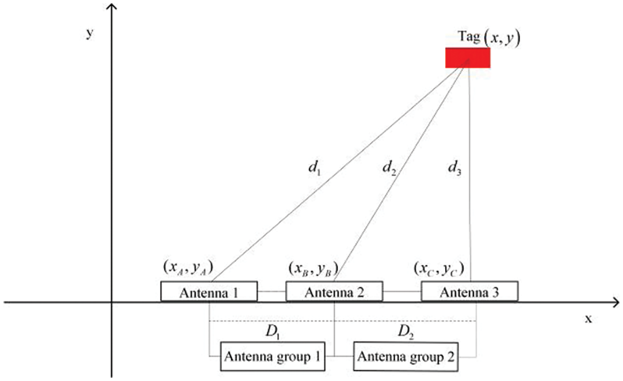
Figure 3: SD-PDOA localization principal diagram
To ensure a sufficiently large measurement area and avoid phase measurement errors caused by whole cycle ambiguity, the distance between antennas is usually set to half the wavelength of the wireless signal. In an indoor planar coordinate system, the coordinates of the tag’s geometric center are
where
Due to the whole cycle ambiguity problem, both sides of Eq. (13) are taken modulo
In this localization system, the antenna array is positioned along the y-axis with a coordinate value of zero. The variables
This section introduces the localization technology used in NLoS and multipath environments. It describes the integration of SD-PDOA and RSSI for passive localization technology in multipath environments. These technologies leverage the channel characteristics of NLoS and multipath environments to eliminate interference caused by NLoS and multipath, thereby improving the accuracy of passive RFID localization.
4.1 Improved Kalman Filter Algorithm
This subsection proposes an improved Kalman filter algorithm that combines standard and biased Kalman filters. Kalman filter is an algorithm for estimating system states and is widely used in indoor localization. The improved Kalman filter algorithm, shown in Table 1, is primarily used for passive localization in NLoS environments. It involves adjusting the parameters of the filter. During the process of optimal estimation, the algorithm reduces the error caused by NLoS by subtracting the noise bias

4.2 Improvement in NLoS Environment Localization Technology
Based on the presented theoretical foundations, we propose a combined localization technology integrating an improved Kalman filter with SD-PDOA in NLoS environments. The procedure starts with computing the variance of the observation values. A threshold criterion is then applied to determine if the signal originates from an NLoS source, as shown in Fig. 4. A biased Kalman filter is used for estimation purposes for signals identified as NLoS, while signals confirmed as LoS are processed using a standard Kalman filter.

Figure 4: Improved Kalman filter and SD-PDOA combined localization technology process flow
4.3 Improvement in Multipath Environment Localization Technology
In a multipath environment, the distances between the antenna array and their relative distances to the tag under test are crucial parameters. The system combines the RSSI trilateration and SD-PDOA hyperbolic solution methods to determine the coordinates of the tag. A minimum of three antennas are required for two-dimensional plane localization.
The RSSI and SD-PDOA combined localization method initially uses the RSSI values received by different antennas, input into the logarithmic path loss model to estimate distances. This is then combined with RSSI trilateration and the Kalman filter technology to produce a set of localization results. Based on these results, a two-dimensional confidence region is established. Results outside this confidence region are discarded as invalid, while those insides are considered valid, thereby achieving precise localization in multipath environments. The specific technology process is illustrated in Fig. 5.

Figure 5: RSSI and SD-PDOA combined localization technology process flow
The RSSI and SD-PDOA combined localization method integrates the wide localization area of the RSSI trilateration and the high accuracy of the SD-PDOA hyperbolic localization method. It overcomes the limitations of low accuracy in RSSI localization and restricted localization range in SD-PDOA, effectively utilizing the strengths of different localization methods to enhance passive localization accuracy in multipath environments.
5 Experiment Results and Discussion
In this section, we evaluate the performance of our proposed method for localizing tags in an indoor setting against existing techniques. We assume that the tags are uniformly distributed in a5 m × 5 m area, and the reader is connected to three or four equally spaced antennas. Baffle is placed between the antennas and tags to emulate NLoS conditions. During simulations, Gaussian white noise with a mean of zero and a variance of 0.1 is introduced into the localization system to simulate phase errors caused by the environment. Gaussian noise with a mean of 3.27, 3.48 and 5.97 and a variance of 0.1 is added to the phases of antennas 1, 2 and 3, respectively, to simulate the phase error introduced by NLoS propagation. The signal frequency is set to 920 MHz with an antenna spacing of 0.1631 m. The URL for the simulation code is provided in Appendix A. The simulation setup is shown in Fig. 6 and 6a.

Figure 6: Simulation deployment diagram (a) NLoS environment; (b) multipath environment
The performance is evaluated in terms of the Root Mean Square Error (RMSE), defined by

Figure 7: NLoS simulation result (a) comparison of localization accuracy; (b) variation of localization accuracy with noise variance under the three antennas test condition
As demonstrated in Fig. 7a, the passive localization method using SD-PDOA combined with an improved Kalman filter demonstrates an increase in localization accuracy of almost 40% compared to the traditional SD-PDOA approach. The four-antenna system demonstrated a 50% improvement in accuracy compared to the three-antenna system. At a distance of 5 m from the antenna, the localization error for the three-antenna system reached the meter level. In contrast, the four-antenna system could achieve an accuracy of 0.4 m, as demonstrated by tag3. The system’s accuracy could be improved to within 0.25 m by optimizing it with the improved Kalman filter algorithm. The paper found that the average localization error for the four-antenna system under NLoS conditions was 0.2 m. The accuracy was determined by uniformly evaluating all tags within a 5 m × 5 m area, with some tags reaching centimeter-level accuracy. Additionally, the measurement noise for phase difference in the antenna array was gradually reduced to 0.01 dB. The RMSE decreased as shown in Fig. 7b.
Simulations were conducted for passive localization in multipath environments using the RSSI and SD-PDOA combined localization technology. Fig. 6b shows the deployment of different tags within a 5 m × 5 m space.
The scatter plot coordinates of the trilateration results based on RSSI generate a 2D confidence area, as shown in Fig. 8a, which indicates that the further a tag is from the antenna array, the larger the confidence ellipse. In Fig. 8b, the 68% confidence area for each tag has minimal overlap, suggesting a low chance of misjudgment in SD-PDOA localization. In Fig. 8c, the 95% confidence area shows a more significant overlap, increasing the likelihood of misjudgments. In Fig. 8d, the confidence areas of Tags 2, 6, and 4 partially overlap. Considering the distribution characteristics of SD-PDOA localization results, this overlap has minimal impact on judgments. To balance the probability of successful judgment and misjudgment, the 68% confidence area is chosen for the combined localization simulation analysis.

Figure 8: RSSI localization scatter plot confidence area: (a) scatter plot; (b) 68% confidence; (c) 95% confidence; (d) 99.7% confidence
As illustrated in Fig. 9a, the success rates for identifying each tag vary based on their spatial positioning. Specifically, Tags 1, 3, and 5 have lower detection success rates, in contrast to the higher rates seen with the other tags. A notable trend is that tags located closer to the center of the antenna array tend to have lower hit rates. This phenomenon is attributed to the smaller confidence regions for these tags, calculated based on the strength of the received signals. While this smaller confidence area results in lower hit rates, it concurrently enhances the overall accuracy of the localization process. The RMSE values for the six tags were calculated based on the 68% confidence area, and a comparison of RMSEs for RSSI trilateration and SD-PDOA hyperbolic localization is made, as shown in Fig. 9b. The error for the combined SD-PDOA and RSSI localization is the smallest, achieving more than a 50% increase in accuracy compared to traditional passive localization methods using SD-PDOA or RSSI alone, with the RMSE for the six tags ranging from 0.3 to 0.5 m in multipath environments. Among these, Tag 3 (2.5, 2) had a smaller SD-PDOA localization error than the combined method. Analysis revealed that when determining using the confidence area, the center of the confidence area for Tag 3 is higher on the y-axis than the actual value, increasing the error on the y-axis. However, as the tag is located directly above the centerline of the antenna array, it is in the optimal area for SD-PDOA localization, hence the smallest error. When tags were further from the antenna array or had larger angles with the array central vertical line, such as Tags 1, 2, 5, and 6, the combined method significantly improved accuracy compared to RSSI and SD-PDOA localization. Therefore, the RSSI and SD-PDOA combined method effectively merged the advantages of both approaches, significantly improving indoor localization accuracy in multipath environments.

Figure 9: Multipath simulation result (a) tag hit rate at different confidence levels; (b) comparison of localization accuracy by different methods
Fig. 10 shows the test scenarios for the passive IoT localization technology. The reader used is Impinj’s R420, with a transmission signal frequency of 924.125 MHz and a transmission power of 32.5 mW. Fig. 10a depicts the NLoS environment test scenario, where the direct path is blocked by a barrier, and the accuracy of localization is measured by varying the distance. Fig. 10b shows the multipath environment test scenario, where tags are dispersed in different positions to analyze the impact of multipath on passive localization performance.

Figure 10: Passive IoT localization technology test scenarios (a) NLoS environment; (b) multipath environment scenarios; (c) multipath environment structure
As shown in Fig. 11a, the passive localization performance of combining SD-PDOA and RSSI with the improved Kalman filter algorithm was compared. The four-antenna system showed an improvement in average localization error at distances of 1, 2.1, and 5 m, compared to the three-antenna system, with approximate improvements of 0.1, 0.3, and 0.5 m, respectively. Under NLoS conditions, the 5 m localization precision could reach 0.46 m. SD-PDOA generally had better localization accuracy than RSSI. By using the proposed technology for passive localization, issues of signal attenuation and increased noise in NLoS environments were resolved.

Figure 11: Test results (a) RMSE in NLoS environment; (b) localization accuracy results in multipath environment
Passive localization tests in the multipath environment depicted in Fig. 11b were conducted using the RSSI and SD-PDOA combined localization method. In the experimental tests, the greater the distance, the larger the phase shift, the larger the confidence area, and the larger the localization error. When the tag was approximately 2 m from the antenna array, the system exhibited a RMSE of0.2 m. At a distance of 4 m, the RMSE increased to 0.4 m. This paper employed a hybrid localization approach that combined RSSI-based localization and SD-PDOA to estimate the localization results and determine the confidence area. It resolved the issues of low accuracy in RSSI-based localization at longer distances and instability in phase localization in SD-PDOA, especially in the presence of multipath interference. Additionally, it avoided the ambiguity in whole cycles inherent in SD-PDOA, effectively merging the advantages of different RF signal parameters to enhance localization accuracy.
The computational process for the proposed method, which combines improved Kalman filter with SD-PDOA, consists of two main parts: SD-PDOA hyperbolic localization and the application of improved Kalman filter. First, the SD-PDOA algorithm calculates the coordinates of the tags by using the phase differences of the signals received by the antennas, with a computational complexity of
For the method combining RSSI and SD-PDOA in a multipath environment, the computational process is mainly divided into three parts. The first part involves triangulation based on RSSI and hyperbolic localization based on SD-PDOA, with a computational complexity of
Tables 2 and 3 present a comparative analysis of different passive localization methods in NLoS and multipath environments, respectively. The proposed method, which combines an improved Kalman filter with SD-PDOA in NLoS environments, along with the method that integrates RSSI with SD-PDOA in multipath environments, demonstrates the lowest RMSE on a unit test area and exhibits the lowest computational complexity. This suggests that the passive RFID localization methods presented in this paper are capable of achieving more accurate localization results in shorter computation times in both multipath and NLoS conditions. This effectively solves the problem of reduced localization accuracy in existing passive RFID localization techniques due to multipath and NLoS interference.


In this paper, we investigate RSSI trilateration and SD-PDOA hyperbolic localization technologies, and signal propagation in NLoS and multipath environments. We propose a combined localization technology that integrates an improved Kalman filter with SD-PDOA and RSSI techniques to address the problem of poor accuracy in passive RFID localization under NLoS and multipath conditions. Extensive simulations and test results demonstrate that the indoor passive RFID localization technology presented here effectively overcomes the limitations of single technologies in complex environments, providing a more efficient and accurate passive localization solution for complex indoor scenarios. The application of this research in machine learning and automated systems could lead to more intelligent, responsive, and efficient AI applications, capable of navigating and interpreting complex indoor spaces with unprecedented precision. This represents a promising direction for future research and development in AI-enhanced indoor localization systems. However, it is important to acknowledge the limitations of our approach. Significant signal attenuation occurs at longer distances between the tag and the reader, resulting in substantial fluctuations in collected data, particularly in carrier phase. As a result, positioning accuracy decreases with increasing distance. In future research, we will focus on improving passive localization techniques to address the challenge of poor accuracy encountered at long distances.
Acknowledgement: The authors would like to thank the editors and reviewers for their valuable work, as well as the supervisor and family for their valuable support during the research process.
Funding Statement: This work was supported in part by the Joint Project of National Natural Science Foundation of China (U22B2004, 62371106), in part by China Mobile Research Institute & X-NET (Project Number: 2022H002), in part by the Pre-Research Project (31513070501), in part by National Key R&D Program (2018AAA0103203), in part by Guangdong Provincial Research and Development Plan in Key Areas (2019B010141001), in part by Sichuan Provincial Science and Technology Planning Program of China (2022YFG0230, 2023YFG0040), in part by the Fundamental Enhancement Program Technology Area Fund (2021-JCJQ-JJ-0667), in part by the Joint Fund of ZF and Ministry of Education (8091B022126) and in part by Innovation Ability Construction Project for Sichuan Provincial Engineering Research Center of Communication Technology for Intelligent IoT (2303-510109-04-03-318020).
Author Contributions: The authors confirm contribution to the paper as follows: methodology, investigation, software, writing: Junyang Liu; research conception and design: Jian Li; writing–review and editing: Jian Li, Guangjun Wen; analysis and interpretation of results: Yuan Li, Yulu Zhang, Gui Li and Shuai Ma; data collection: Yi He, Yue Liu and Haiwen Yi; analysis and interpretation of results: Xu Zhang, Xiaotao Xu and Jinyao He. All authors reviewed the results and approved the final version of the manuscript.
Availability of Data and Materials: The data that support the findings of this study are available from the corresponding author, Jian Li, upon reasonable request.
Conflicts of Interest: The authors declare that they have no conflicts of interest to report regarding the present research.
References
1. I. E. Radoi, D. Cirimpei, and V. Radu, “Localization systems repository: A platform for open-source localization systems and datasets,” in Proc. 2019 Int. Conf. Indoor Positioning Indoor Navigation, Pisa, Italy, 2019, pp. 1–8. [Google Scholar]
2. W. Fang, C. Xie, and B. Ran, “An accurate and real-time commercial indoor localization system in LTE networks,” IEEE Access, vol. 9, pp. 21167–21179, Feb. 2021. doi: 10.1109/ACCESS.2020.3034654. [Google Scholar] [CrossRef]
3. S. Xu et al., “Bluetooth, floor-plan, and microelectromechanical systems-assisted wide-area audio indoor localization system: Apply to smartphones,” IEEE Trans. Ind. Electron., vol. 69, no. 11, pp. 11744–11754, Nov. 2022. [Google Scholar]
4. S. Wei, J. Wang, and Z. Zhao, “Poster abstract: LocTag: Passive WiFi tag for robust indoor localization via smartphones,” in Proc. IEEE INFOCOM WKSHPS, Toronto, ON, Canada, 2020, pp. 1342–1343. [Google Scholar]
5. A. Mahmoud, P. Coser, H. Sadruddin, and M. Atia, “Ultra-wideband automatic anchor’s localization for indoor path tracking,” in Proc. IEEE Sensors, Dallas, TX, USA, 2022, pp. 1–4. [Google Scholar]
6. M. I. AlHajri, N. T. Ali, and R. M. Shubair, “Indoor localization for IoT using adaptive feature selection: A cascaded machine learning approach,” IEEE Antennas Wirel. Propag. Lett., vol. 18, no. 11, pp. 2306–2310, Nov. 2019. doi: 10.1109/LAWP.2019.2915047. [Google Scholar] [CrossRef]
7. A. R. Chatzistefanou and A. G. Dimitriou, “Tag localization by handheld UHF RFID reader and optical markers,” in Proc. 2022 IEEE Int. Conf. RFID Technol. Appl., Cagliari, Italy, 2022, pp. 9–12. [Google Scholar]
8. A. Buffi, A. Michel, P. Nepa, and B. Tellini, “RSSI measurements for RFID tag classification in smart storage systems,” IEEE Trans. Instrum. Meas., vol. 67, no. 4, pp. 894–904, Apr. 2018. doi: 10.1109/TIM.2018.2791238. [Google Scholar] [CrossRef]
9. A. Zaric, C. C. Cruz, A. M. de Matos, M. R. Da Silva, J. R. Costa and C. A. Fernandes, “Pseudo localization principle for RFID based smart blood stock system,” in Proc. Eur. Conf. Antennas Propag., 2015, pp. 1–4. [Google Scholar]
10. A. Y. Chang, D. R. Tsai, T. C. Liu, C. J. Chen, and I. H. Jeng, “Performance evaluation of real-time indoor positioning with active-RFID and CSS-based nano lock system,” in Proc. 5th Int. Joint Conf. INC, IMS, IDC, 2009, pp. 1896–1898. [Google Scholar]
11. T. Liu, Y. Liu, L. Yang, Y. Guo, and C. Wang, “BackPos: High accuracy backscatter positioning system,” IEEE Trans. Mobile Comput., vol. 15, no. 3, pp. 586–598, Mar. 2016. doi: 10.1109/TMC.2015.2424437. [Google Scholar] [CrossRef]
12. Z. Fang et al., “Beamforming design for multi-antenna multi-tag symbiotic radio backscatter systems,” AEU Int. J. Electron. Commun., vol. 170, pp. 154820, 2023. doi: 10.1016/j.aeue.2023.154820. [Google Scholar] [CrossRef]
13. A. Vena, I. Illanes, L. Alidieres, B. Sorli, and F. Perea, “RFID based indoor localization system to analyze visitor behavior in a museum,” in Proc. 2021 IEEE Int. Conf. RFID Technol. Appl., Delhi, India, 2021, pp. 183–186. [Google Scholar]
14. E. Shen, W. Yang, X. Wang, and S. Mao, “Foreign material detection and localization in stored grain with passive RFID tag arrays,” in Proc. 2023 IEEE Int. Conf. RFID Technol. Appl., Aveiro, Portugal, 2023, pp. 193–196. [Google Scholar]
15. E. DiGiampaolo, F. Martinelli, and F. Romanelli, “Exploiting the orientation of trilateration UHF RFID tags in robot localization and mapping,” in Proc. 2022 IEEE Int. Conf. RFID Technol. Appl., Cagliari, Italy, 2022, pp. 5–8. [Google Scholar]
16. S. Megalou, A. Bletsas, T. Yioultsis, and A. G. Dimitriou, “Power and phase variation of backscattered RFID signal with respect to the incident power at the tag,” in Proc. 2021 IEEE Int. Conf. RFID Technol. Appl., Delhi, India, 2021, pp. 36–39. [Google Scholar]
17. S. Feng et al., “Three-dimensional robot localization using cameras in wireless multimedia sensor networks,” J. Netw. Comput. Appl., vol. 146, pp. 102425, 2019. doi: 10.1016/j.jnca.2019.102425. [Google Scholar] [CrossRef]
18. A. Buffi, A. Motroni, P. Nepa, B. Tellini, and R. Cioni, “A SAR-based measurement method for passive-tag localization with a flying UHF-RFID reader,” IEEE Trans. Instrum. Meas., vol. 68, no. 3, pp. 845–853, Mar. 2019. doi: 10.1109/TIM.2018.2857045. [Google Scholar] [CrossRef]
19. P. Tripicchio et al., “A synthetic aperture UHF RFID localization method by phase unwrapping and hyperbolic intersection,” IEEE Trans. Autom. Sci. Eng., vol. 19, no. 2, pp. 933–945, Apr. 2022. doi: 10.1109/TASE.2021.3057433. [Google Scholar] [CrossRef]
20. A. Tzitzis et al., “Real-time 3D localization of RFID-tagged products by ground robots and drones with commercial off-the-shelf RFID equipment: Challenges and solutions,” in Proc. RFID, Orlando, FL, USA, 2020, pp. 1–8. [Google Scholar]
21. W. Wang, Y. Zhang, and L. Tian, “TOA-based NLoS error mitigation algorithm for 3D indoor localization,” China Commun., vol. 17, no. 1, pp. 63–72, Jan. 2020. doi: 10.23919/JCC.2020.01.005. [Google Scholar] [CrossRef]
22. W. Jiang and B. Ding, “TDOA localization scheme with NLoS mitigation,” in Proc. 2020 IEEE 92nd Veh. Technol. Conf., Victoria, BC, Canada, 2020, pp. 1–4. [Google Scholar]
23. L. Gui, S. Xu, F. Xiao, F. Shu, and S. Yu, “Non-line-of-sight localization of passive UHF RFID tags in smart storage systems,” IEEE Trans. Mob. Comput., vol. 21, no. 10, pp. 3731–3743, 1 Oct. 2022. doi: 10.1109/TMC.2021.3058952. [Google Scholar] [CrossRef]
24. C. Tian, Y. Ma, and B. Wang, “Cooperative localization for passive RFID backscatter networks and theoretical analysis of performance limit,” IEEE Trans. Wirel. Commun., vol. 22, no. 2, pp. 1388–1402, Feb. 2023. doi: 10.1109/TWC.2022.3204679. [Google Scholar] [CrossRef]
25. F. Xiao, Z. Wang, N. Ye, R. Wang, and X. Y. Li, “One more tag enables fine-grained RFID localization and tracking,” IEEE/ACM Trans. Netw., vol. 26, no. 1, pp. 161–174, Feb. 2018. doi: 10.1109/TNET.2017.2766526. [Google Scholar] [CrossRef]
26. A. Motroni, G. Cecchi, A. Buffi, and P. Nepa, “Indoor multipath channel modeling effects on UHF-RFID localization with synthetic arrays,” in Proc. 2023 17th Eur. Conf. Antennas and Propag., Florence, Italy, 2023, pp. 1–5. [Google Scholar]
27. J. Wang, Y. Ma, Y. Zhao, and K. Liu, “A multipath mitigation localization algorithm based on MDS for passive UHF RFID,” IEEE Commun. Lett., vol. 19, no. 9, pp. 1652–1655, Sept. 2015. doi: 10.1109/LCOMM.2015.2450217. [Google Scholar] [CrossRef]
28. Y. Ma, B. Wang, S. Pei, Y. Zhang, S. Zhang, and J. Yu, “An indoor localization method based on AOA and PDOA using virtual stations in multipath and NLoS environments for passive UHF RFID,” IEEE Access, vol. 6, pp. 31772–31782, Jun. 2018. doi: 10.1109/ACCESS.2018.2838590. [Google Scholar] [CrossRef]
29. Y. Ma, H. Liu, Y. Zhang, and Y. Jiang, “The influence of the nonideal phase offset on SAR-based localization in passive UHF RFID,” IEEE Trans. Antennas Propag., vol. 68, no. 8, pp. 6346–6354, Aug. 2020. doi: 10.1109/TAP.2020.2982448. [Google Scholar] [CrossRef]
30. A. Motroni, G. Cecchi, A. Ria, and P. Nepa, “Passive UHF-RFID technology: Integrated communication, localization and sensing,” IEEE J. Radio Freq. Identification, vol. 7, pp. 564–572, 2023. doi: 10.1109/JRFID.2023.3301093. [Google Scholar] [CrossRef]
31. S. Zhang, S. Gao, G. Wang, and Y. Li, “Robust NLoS error mitigation method for TOA-based localization via second-order cone relaxation,” IEEE Commun. Lett., vol. 19, no. 12, pp. 2210–2213, Dec. 2015. doi: 10.1109/LCOMM.2015.2482979. [Google Scholar] [CrossRef]
32. J. Guo, L. Zhang, W. Wang, and K. Zhang, “Hyperbolic localization algorithm in mixed LoS-NLoS environments,” in Proc. 2020 IEEE Int. Conf. Power, Intell. Comput. Syst., Shenyang, China, 2020, pp. 847–850. [Google Scholar]
33. C. Liao, K. Xu, X. Xia, W. Xie, and M. Wang, “AOA-assisted fingerprint localization for cell-free massive MIMO system based on 3D multipath channel model,” in Proc. 2020 IEEE 6th Int. Conf. Comput. Commun., Chengdu, China, 2020, pp. 602–607. doi: 10.1109/ICCC51575.2020.9345306. [Google Scholar] [CrossRef]
34. M. N. De Sousa and R. S. Thomä, “Mobile station localization emitter in Urban NLoS using multipath ray tracing fingerprints and machine learning,” in Proc. 2018 8th Int. Conf. Localization and GNSS, Guimaraes, Portugal, 2018, pp. 1–6. doi: 10.1109/ICL-GNSS.2018.8440898. [Google Scholar] [CrossRef]
35. Y. Zhao, Y. Liu, and L. M. Ni, “VIRE: Active RFID-based localization using virtual reference elimination,” in Proc. 2007 Int. Conf. Parallel Process., Xi’an, China, 2007, pp. 56. doi: 10.1109/ICPP.2007.84. [Google Scholar] [CrossRef]
36. C. Peng, H. Jiang, and L. Qu, “Deep convolutional neural network for passive RFID tag localization via joint RSSI and PDOA fingerprint features,” IEEE Access, vol. 9, pp. 15441–15451, Jan. 2021. doi: 10.1109/ACCESS.2021.3052567. [Google Scholar] [CrossRef]
37. S. J. Patel and M. J. Zawodniok, “3D localization of RFID antenna tags using convolutional neural networks,” IEEE Trans. Instrum. Meas., vol. 71, pp. 1–11, Feb. 2022. doi: 10.1109/TIM.2022.3146604. [Google Scholar] [CrossRef]
The research code at https://github.com/blinkwalk/Passive-IoT-Localization-Technology-Based-on-SD-PDOA-in-NLOS-and-Multi-path-Environments.git, which was last accessed on Apr. 12, 2024.
Cite This Article
 Copyright © 2024 The Author(s). Published by Tech Science Press.
This work is licensed under a Creative Commons Attribution 4.0 International License , which permits unrestricted use, distribution, and reproduction in any medium, provided the original work is properly cited.
 Downloads
 Citation Tools