
 Submit a Paper
 Propose a Special lssue
 Open Access
ARTICLE

Development of a Novel Noise Reduction Algorithm for Smart Checkout RFID System in Retail Stores
1 Department of Mechanical Engineering, Faculty of Engineering, Universiti Malaya, Kuala Lumpur, 50603, Malaysia
2 Centre for Sustainable and Smart Manufacturing (CSSM), Faculty of Engineering, Universiti Malaya, Kuala Lumpur, 50603, Malaysia
3 Department of Industrial Engineering, College of Engineering, Alfaisal University, Riyadh, 11533, Saudi Arabia
4 Department of Industrial Engineering, College of Engineering, King Saud University, P. O. Box 800, Riyadh, 11421, Saudi Arabia
* Corresponding Author: Mohammed A. H. Ali. Email:
Computers, Materials & Continua 2024, 80(1), 1277-1304. https://doi.org/10.32604/cmc.2024.049257
Received 01 January 2024; Accepted 06 May 2024; Issue published 18 July 2024
 View Full Text
 Download PDF
Abstract
This paper presents a smart checkout system designed to mitigate the issues of noise and errors present in the existing barcode and RFID-based systems used at retail stores’ checkout counters. This is achieved by integrating a novel AI algorithm, called Improved Laser Simulator Logic (ILSL) into the RFID system. The enhanced RFID system was able to improve the accuracy of item identification, reduce noise interference, and streamline the overall checkout process. The potential of the system for noise detection and elimination was initially investigated through a simulation study using MATLAB and ILSL algorithm. Subsequently, it was deployed in a small-scale environment to validate its real-world performance. Results show that RFID with the proposed new algorithm ILSL and AI basket is capable of accurately detecting the related items while eliminating noise originating from unrelated objects, achieving an accuracy rate of 88%.Keywords
In recent years, retail stores have seen substantial transformation, resulting in the emergence of smart shopping systems designed to offer new, dependable, and comfortable shopping experience. These innovations enhance and simplify the purchasing experience, primarily by eliminating the inconveniences encountered during checkout [1]. Current retail stores use two major technologies to scan products during checkout, namely, barcode and RFID systems. Several concerns have arisen with the barcode system, including barcode damage or scratches [2], long checkout times as it is done one at a time [3–5] and the presence of noise and human errors that creates a negative impression of the system [6].
In contrast, the adoption of RFID technology has improved the process of monitoring and recognizing items in a number of retail outlets. RFID technology, which uses radio waves, facilitates the implementation of Automatic Identification Technology (AIT) though RFID tags. RFID readers can capture data from RFID tags that are within the range of the RFID reader, simplifying the process of gathering information in an efficient and convenient manner. This feature has proven extremely useful in a variety of applications, including product tracking, asset management, inventory records, and cashless payment systems [7]. Nevertheless, certain limitations have been identified during the implementation of RFID systems such as noise and uncertainties under various conditions, which will be further elaborated.
Nisha developed RFID systems for libraries to streamline stocktaking processes [8]. However, a challenge arose when the data from RFID tags could not be retrieved at the edges of bookshelves, requiring manual removal of books for tag reading, leading to manual interaction with the automated system. Interference in the magnetic field, caused by factors such as the presence of medical equipment, metallic objects, liquid, glass, and moist environments, can lead to inaccurate readings by the RFID readers [9]. These factors can also impact the reading rates and accuracy. This is a common challenge in healthcare facilities where the constant presence of medical equipment and materials can disrupt RFID-based management systems.
Aboelmaged et al. highlighted that RFID technology faces technical challenges related to the frequencies variation of tags and systems in the patient and medical asset management operations [10]. These technical obstacles can lead to interoperability issues, making difficulties for different RFID systems to communicate effectively. This lack of compatibility can reduce efficiency and increase costs since different RFID systems may require different hardware, software, and data processing solutions. Reader collision is a common problem in RFID systems, as noted by Golsorkhtabaramiri et al. [11], occurring when multiple readers attempt to communicate with tags simultaneously in close proximity. This concurrent activity can cause interference, leading to errors such as false readings, data corruption, and decreasing the system performance. the reader collision can also result in bandwidth consumption, data reading delays, and overall system inefficiency [12]. Athauda et al. highlighted that RFID technology may face environmental constraints in the food industry, such as humidity and temperature levels. that affects its functionality and reliability [13]. For example, high humidity levels can damage or reduce the functionality of RFID tags due to the absorption of moisture. This reduces the signal strength and potentially causes a misreading of RFID tags. Moreover, the excessive humidity can weaken the adhesive the RFID tags [14]. Extreme temperatures, whether too high or low, can also harm RFID tags through thermal shock, leading to tag malfunction or damage [5].
Zhou et al. have emphasised that RFID tag collision as a prevalent issue in logistics, occurring when multiple RFID tags are in close to each other’s during simultaneous reading [15]. This proximity causes signal interference and reduces tag readability due overlapping of the electromagnetic fields. Pal discussed two environmental barriers that RFID may encounter, namely, tag collisions and interference from medical equipment [16]. The tag collisions involve multiple tags trying to communicate simultaneously with the reader, causing signal interference and hindering the identification process. This can affect the speed and efficiency of tag identification. Xiang et al. discussed the potential challenges that are faced by RFID systems in the healthcare settings, emphasizing how interference from medical equipment like Magnetic Resonance Imaging (MRI) machines, Computed Tomography (CT) scanners, and X-ray machines can disrupt the performance of RFID tags and readers [17]. They highlighted how the strong electromagnetic fields generated by these devices can lead to signal interference, impacting tag readability and communication reliability [18]. Additionally, it was also noted that metal objects and liquids that are commonly found in healthcare environments, can also hinder RFID system performance by causing signal attenuation and absorption [19].
In the grocery retail industry, Karuppuswami et al. [20] pointed out a limitation related to the reading range of RFID technology, which is defined as the distance between the reader and the tag. This limitation can result in inaccurate inventory management as some products may not detect by the reader, potentially leading to issues like overstocking or stockouts.
Nitin Shah et al. addressed the challenge of simultaneous responses from multiple RFID tags in indoor positioning systems used in educational institutions with robots [21]. The interference and overlapping of signals can occur when multiple tags are present in the same space, resulting in inaccurate readings [22]. Furthermore, there are technical limitations related to the memory capacity of RFID tags, noting that while these tags can store data permanently, their storage capacity is limited [23]. This constraint can pose challenges in the applications requiring extensive data storage on tags, such as supply chain management or asset tracking [24].
According to Aliasgari et al. [25], one of the challenges associated with Ultra-Wideband (UWB) chipless RFID readers is the issue of reader sensitivity. They noted that the intricate nature of signals used in UWB chipless RFID technology can lead to issues with reader sensitivity, making it difficult for readers to accurately detect and decode the signals from tags. Shen et al. discussed the issue of speed and movement of tags in RFID technology within the information services industry [26]. In some applications, such as inventory management or asset tracking, tags may need to be read while they are moving at high speeds. This can pose challenges, especially in environments with a high volume of tags or where tags move quickly and unpredictably, such as in warehouse or logistics settings.
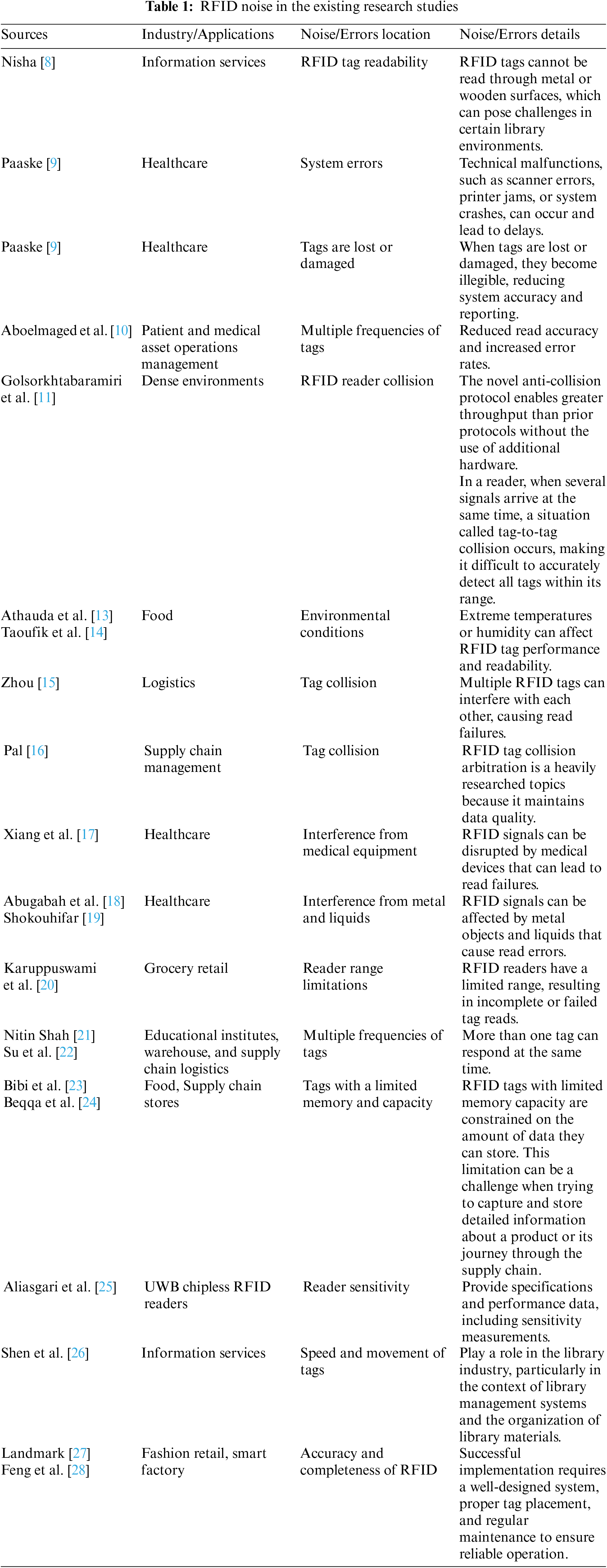
The accuracy and completeness of RFID data pose a significant challenge when implementing RFID technology in the fashion retail industry, due to the reliability and thoroughness of the information that are transmitted between RFID tags and readers [27]. As the fashion industry products are often complex with multiple variants, it is crucial to have accurate and complete data to ensure efficient inventory management, streamlined supply chain operations, and improved customer experiences. However, issues may arise when RFID technology fails to capture all relevant data accurately, leading to inaccuracies or omissions that can result in stockouts, overstocking, or misplaced items [28]. Data presented in Table 1 lists the observed RFID noise documented in the existing research studies.
In this work, the development of smart checkout system, known as the AI basket, will be built to integrate a novel AI algorithm with RFID system for noise elimination. This will enable the automatic self-scanning of items and ensure greater accuracy in identifying and recording each item, minimizing errors, and further optimizing the checkout process. The implementation of a smart checkout system using RFID and the proposed AI algorithm will allow for the enhancement of customer satisfaction, operational efficiency boost, and provision of an exceptional retail experience.
The contribution of this paper can be summarized as follows:
• This research aims to develop a highly robust RFID checkout system with the capability to eliminate the noise using a novel algorithm, known as improved laser simulator logic (ILSL).
• The proposed system has been rigorously evaluated through both simulation and experimental works to demonstrate its effectiveness and accuracy. The testing was conducted on a smaller scale to evaluate the system’s performance in real-world environment.
2 Development of Smart Checkout System
The development of a smart checkout system is carried out in three stages. In the first stage, the improved laser simulator logic approach for eliminating the noise in smart RFID checkout system will be derived, as detailed in Section 2.1. The second stage involves the development of the simulation study using MATLAB to evaluate the system’s ability to detect and eliminate noise while accurately identifying items, as discussed in Section 2.2. Finally, in the third stage, the fully developed system is deployed in a small-scale experimental setup to evaluate the performance of the proposed smart checkout system in real-world scenarios, as outlined in Section 2.3.
2.1 Improved Laser Simulator Logic Approach
A novel approach called Improved Laser Simulator Logic (ILSL) is developed to reduce the noise and errors in RFID systems. The original concept of laser simulator logic (LSL) for fuzzification and defuzzification in control systems with complex linguistic variable membership functions [29] will be significantly enhanced by the proposed ILSL to make it more useful and simple in noise elimination applications. Both LSL and ILSL are capable of handling noise through the high inference of linguistic variables with a dynamic range of membership functions. This will help to overcome the limitations of fuzzy logic in dealing with high overlapping between linguistic variables, as shown in Fig. 1.
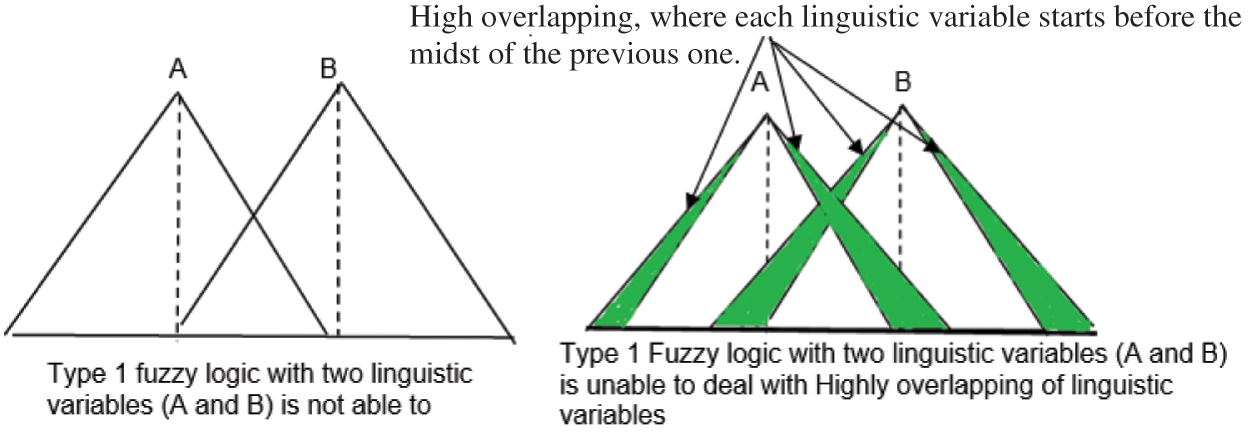
Figure 1: Fuzzy logic drawbacks with high overlapping
Eqs. (1)–(6) describe the fuzzification system with high and low overlapping in both LSL and ILSL. The primary differences between them will occur during the calculation of membership value, as indicated in Eqs. (7)–(10). The main differences between the original and the proposed improved LSL are summarized as follows:
• A new function has been introduced to eliminate the impact of a linguistic variable non-appearance, as shown in Eqs. (7) and (8).
• A new function that can determine the membership values for any crisp input, whether it involves low or high overlapping between linguistic variables, as outlined in Eq. (9).
• The main impact of ILSL is the formulation of a new general equation for finding the membership value of linguistic variables in both high and low overlapping cases, as presented in Eq. (10).
The laser simulator logic algorithm relies heavily on the proportional correlation between the position of crisp input/output values and the complete spectrum of input/output linguistic variables. This relationship is depicted by the membership value of the crisp input/output, as shown in Fig. 2. Essentially, the membership value is calculated based on the ratio of the position of the input crisp value to the range of the input linguistic variables, as defined in Eq. (1). These proportional effects of the input set will subsequently impact the output sets based on the rules of the fuzzy inference system.
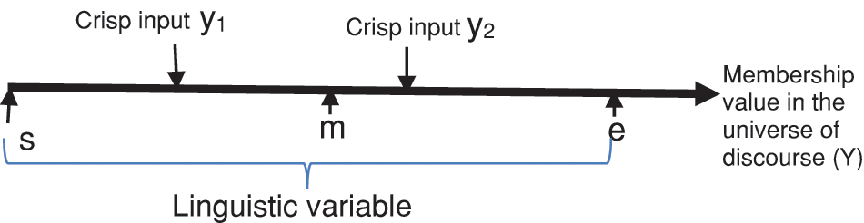
Figure 2: Inference system for a single linguistic variable in laser simulator logic
The membership of a fuzzy set (R) within the universe of discourse (Y) can be defined as follows:
where s, e and m are the starting, ending and midst of linguistic variable as illustrated in Fig. 2.
For y = y1 and y = y2 as shown in Fig. 2, the membership can be calculated as:
The cumulative sum of membership values for a crisp input across all inferred linguistic variables must satisfy Eq. (2):
where j represents the total number of overlapped linguistic variables.
2.1.1 Improved Laser Simulator Membership Derivation
The improved Laser simulator logic algorithm equations can be derived as follows:
Let’s assume j overlapped-linguistic variables within the input set X, each characterized by the following beginning, ending, and midst points as shown in Fig. 3:
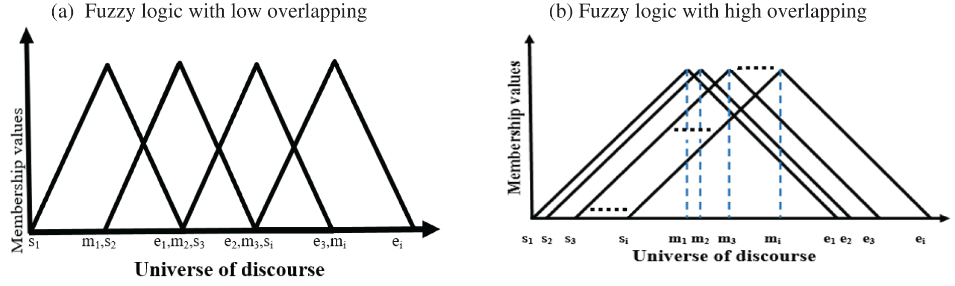
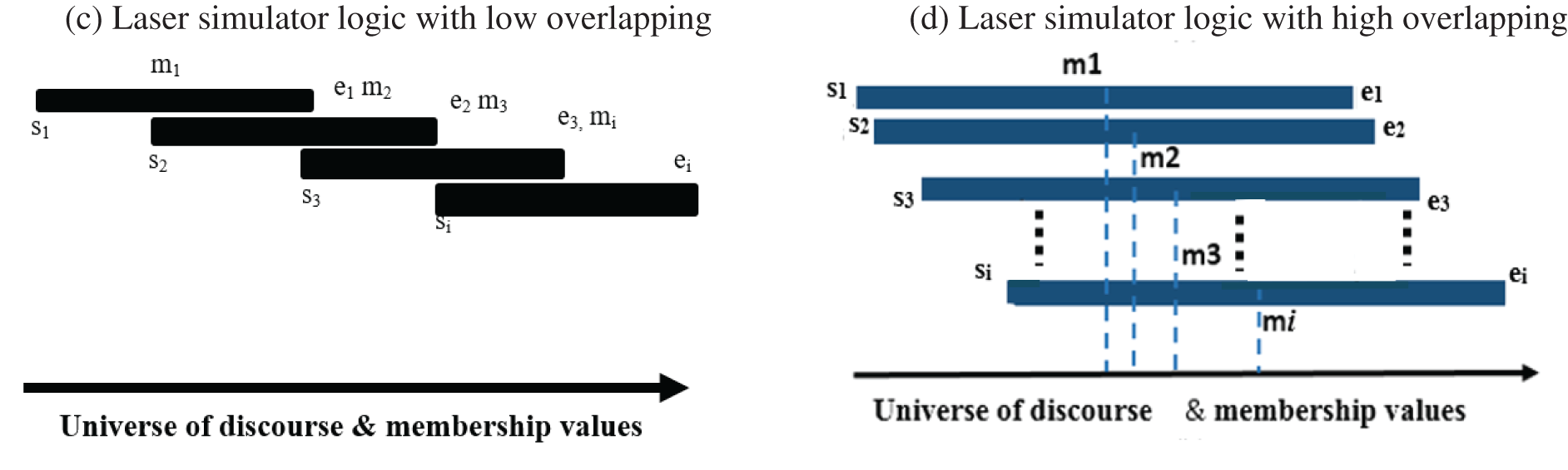
Figure 3: Types of overlapping in membership functions for triangular fuzzy logic and laser simulator logic
- s1, s2, s3,…, sj represent the starting points of the linguistic variable ranges
- e1, e2, e3,…, ej indicate the ending points of the linguistic variable ranges
- and m1, m2, m3, …, mj correspond to the midpoint values within the linguistic variable ranges.
It is essential to formulate a general equation that can be used to calculate the membership value scenarios with both low and high overlapping. To achieve this, the following equations will be derived:
The membership values in lowly overlapping situations can be calculated using Eq. (1).
The cumulative membership value in lowly overlapping cases for a specific crisp input can then be calculated using Eq. (3):
The accumulative membership values for highly overlapping case can be written as in Eq. (4):
where ΔD in Eq. (4), has the values as in Eq. (5):
To simplify the sub-ranges in Eqs. (4) and (5), ΔD is defined in Eq. (6). This enables the calculation of the membership value of the crisp input linguistic variable at any position within the universe of discourse range, whether its position is located before or after the midpoint linguistic variable mi. This can be determined using the following expression:
Thus, Eq. (5) will be transformed into Eq. (6):
To address situations where the starting and ending points of linguistic variables may not adhere to a sequential order and can appear randomly within the universe of discourse, a step function
To eliminate the impact of a linguistic variable non-appearance, one can utilize Eq. (8):
To formulate an equation that assists in determining membership values for any crisp input, whether it involves low or high overlapping between linguistic variables, the term
The general equation for finding the membership value of linguistic variables in both high and low overlapping cases is defined as in Eq. (10):
2.1.2 ILSL Implication and Defuzzification
The implication process in both LSL and ILSL follows the princles of fuzzy logic, where the membership values of linguistic variables in the input set is implicated onto the corresponding linguistic variables in the output set, adhering to the rules of the fuzzy inference system, as described in Eq. (11).
where Zi represents the range of the output linguistic variable, while zi represents the implication result of the input on the output based on fuzzy rules. The crisp output can be determined by calculating the average value of the implication values of zi, as specified in Eq. (12):
where the value of ‘n’ corresponds to the number of times the rules’ implications affect the values of the output linguistic variables.
2.1.3 Implementation of Improved Laser Simulator Logic with Smart Checkout RFID System
The Improved Laser Simulator Logic (ILSL) streamlines the checkout process by accurately differentiating between desired and undesired items, thereby enhancing the overall checkout experience.
The implementation of the ILSL involves two primary steps:
i. Defining input and output membership functions.
ii. Applying laser simulator logic rules for decision making.
In this particular application, two input sets are employed: the distance of the tags to the reader and the length of the conveyor belt. Each input set is divided into five possible ranges, with each range associated with a linguistic variable. For instance, the linguistic variables of first input set: the distance of tags = {too short, short, moderate, long, too long}. Similarly, the length of conveyor distance has been divided into 5 possible ranges with 5 linguistic variables. The linguistic variables of the second input set: Length = { far left, near left, exact, near right, far right}. The output of the laser simulator logic system is a decision on whether the detected item is a desired item or noise. This output set also consists of five linguistic variables = {noise, possible noise, possible object, object}. Fig. 4 provides a visual representation of the two input sets used in this application and the locations of their corresponding linguistic variables.
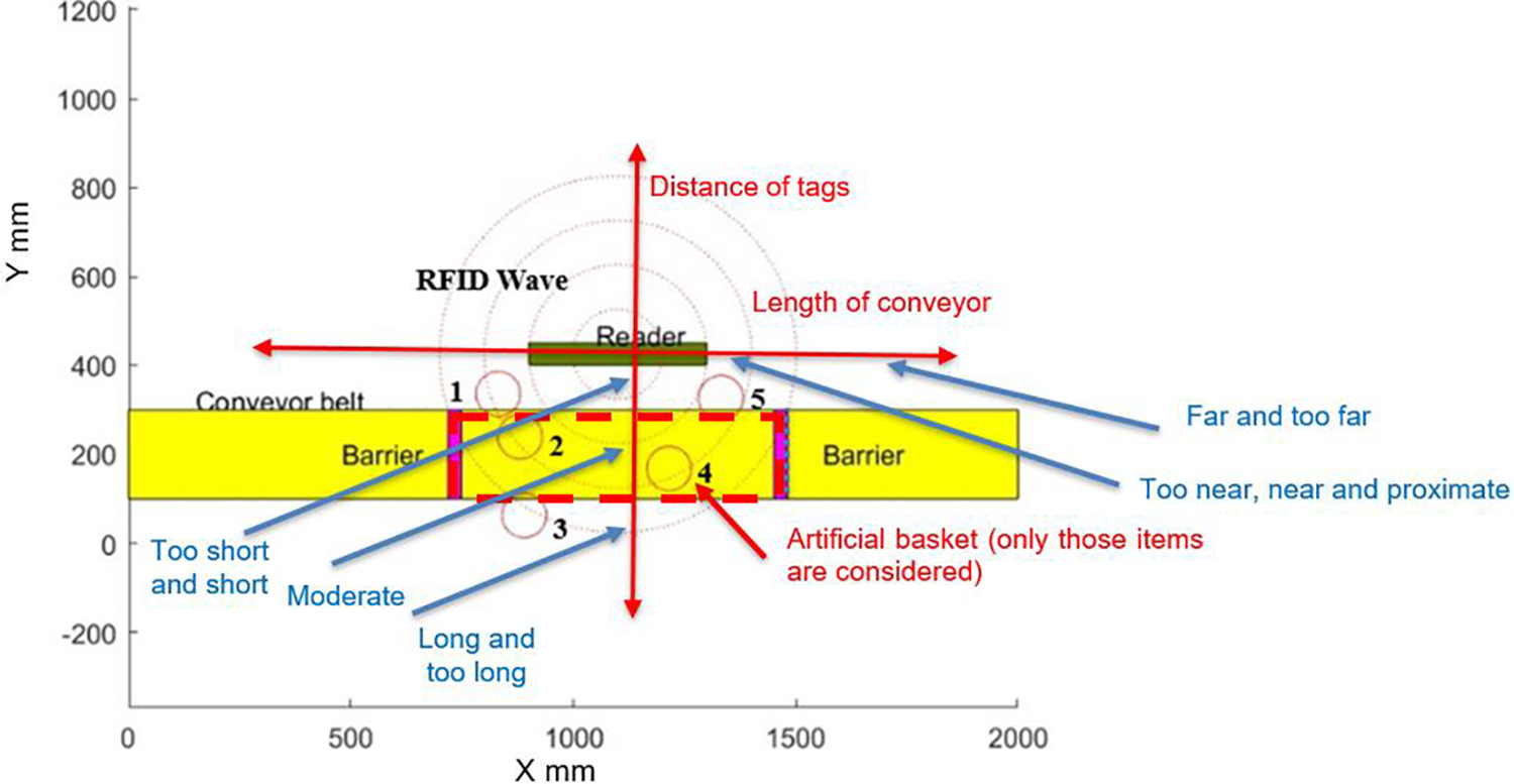
Figure 4: Details of improved laser simulator logic input sets and the locations of their linguistic variables
The RFID system becomes noisy in the following scenarios:
– objects that are related in the next queue for another costumer.
– objects that are located below or on top of the conveyor.
– objects that are located beside the cashier.
Therefore, there is a need to develop an AI system capable of handling such noise. To address the noise in AI decision-making, a diagram illustrating all possible decisions is presented in Fig. 5. This diagram maps the linguistic variable of inputs, distance and length to the decision.
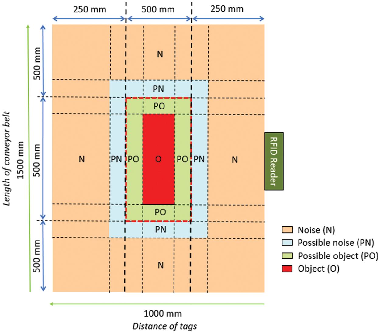
Figure 5: The measurement dimensions for each linguistic variable employed in this study
In this study, the performance of laser simulator logic will be compared to fuzzy logic under two conditions: (a) Without high overlapping between the linguistic variables and (b) With high overlapping between the linguistic variables.
(a) Without high overlapping between the linguistic variables
Table 2 shows the linguistic variables with minimal overlapping, accompanied by their dimensions, measured in both input units (mm) and output (percentage). Fig. 6a,b demonstrates the application of both fuzzy logic and laser simulator logic algorithms in a scenario where there is minimal overlap between the linguistic variables.
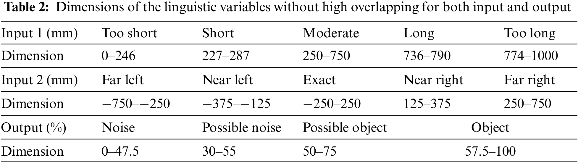
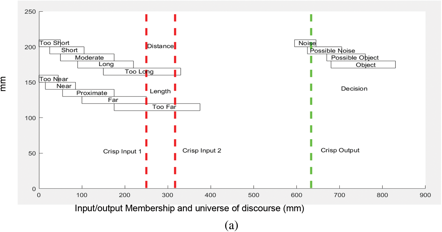
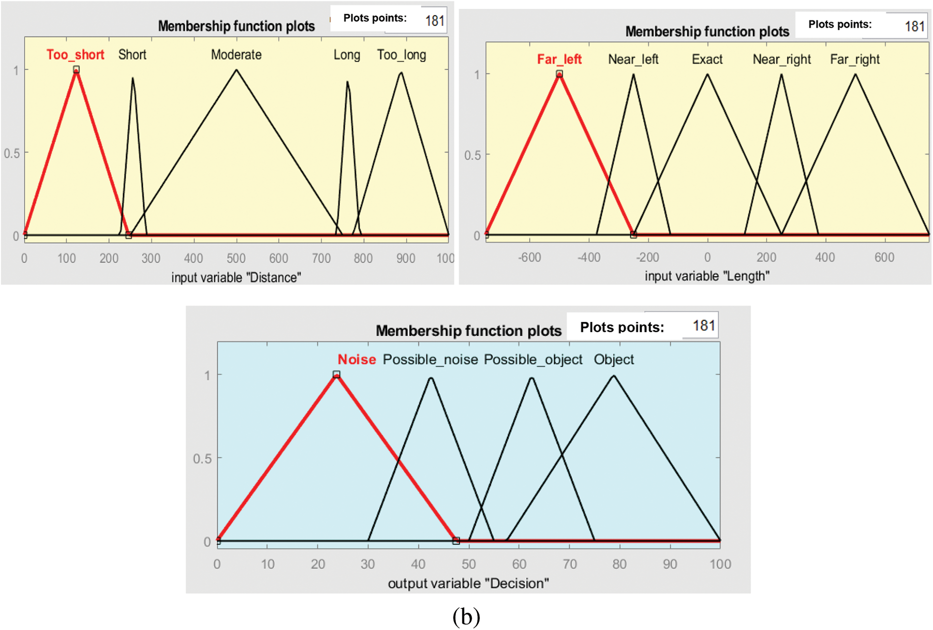
Figure 6: Membership functions without high overlapping: (a) laser simulator logic (b) fuzzy logic
(b) With high overlapping between the linguistic variables
Table 3 depicts the dimensions of linguistic variables with high overlapping for both input and output. It shows crisp inputs encompassing all potential input scenarios, along with crisp outputs calculated using both fuzzy logic and laser simulator logic algorithms. The measurements of linguistic variables are expressed in input units (mm) and output (percentage). Fig. 7a,b illustrates the high overlapping among the values of linguistic variables in the implementation of both fuzzy logic and laser simulator logic algorithms.
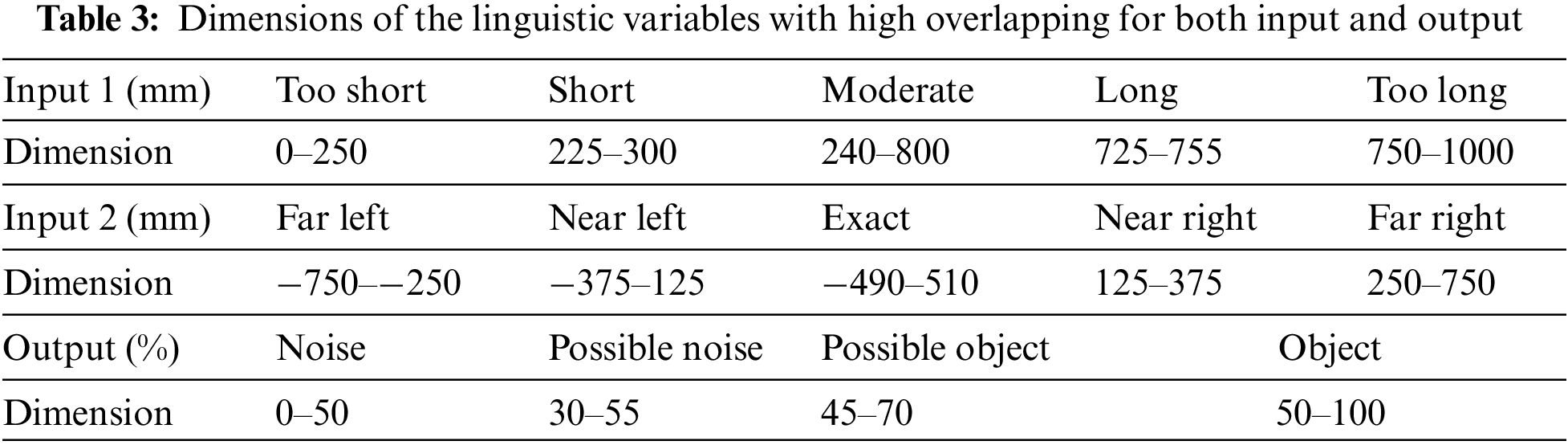
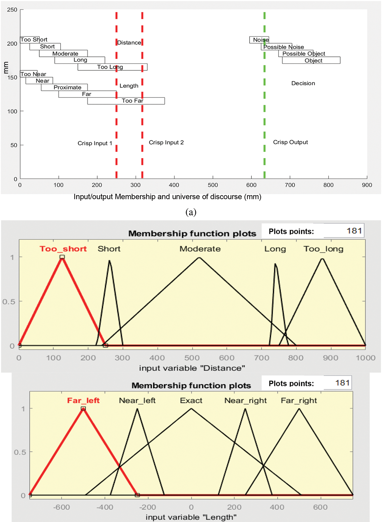
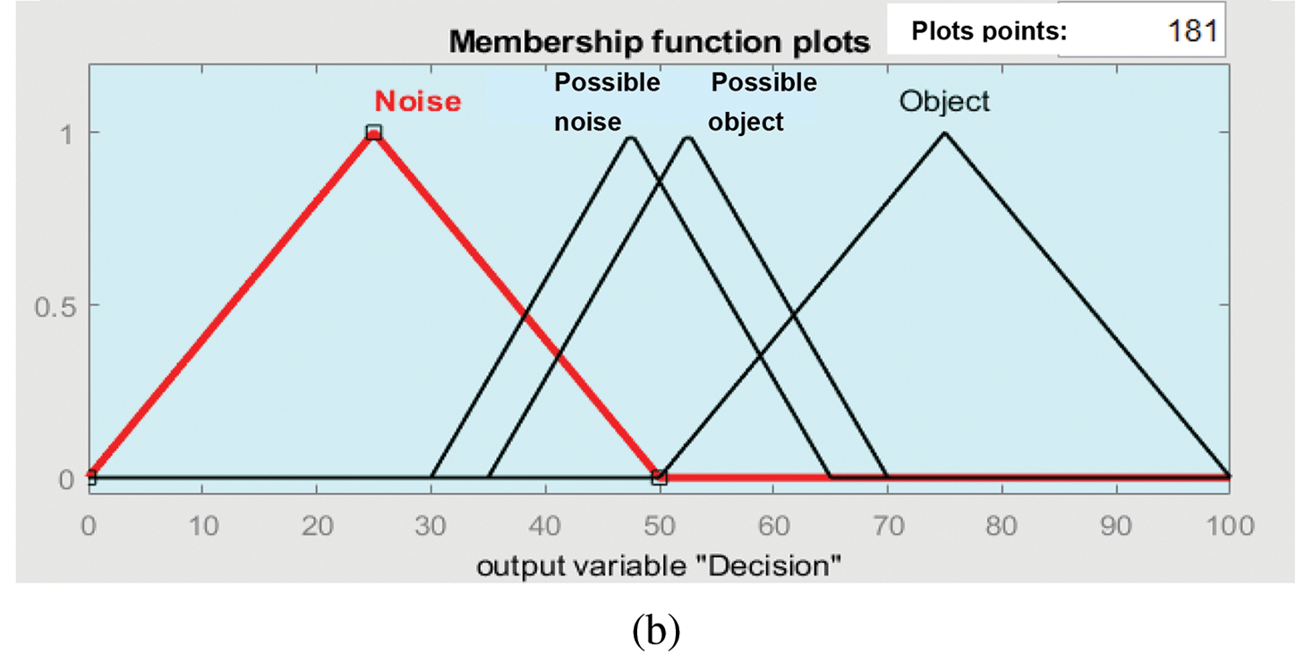
Figure 7: Membership functions with high overlapping: (a) laser simulator logic (b) fuzzy logic
The laser simulator logic and fuzzy logic rules are applied to categorize objects based on their distance and length measurements. The input fuzzy sets consist of the distance of the tags from the reader {too short, short, moderate, long, too long}, the length of the conveyor belt {far left, near left, exact, near right, far right}, and the output decision {noise, possible noise, possible object, object}.
The rules outline the connection between the input linguistic variables (distance and length) and the output (decision). The selection of rules for laser simulator logic and fuzzy logic is based on Fig. 5:
1. If distance is too short and length is far left, then decision is noise.
2. If distance is short and length is near left, then decision is possible noise.
3. If distance is short and length is exact, then decision is possible object.
4. If distance is moderate and length is exact, then decision is object.
5. If distance is long and length is near right, then decision is possible noise.
6. If distance is too long and length is far right, then decision is noise.
2.2 Simulation of a Smart Checkout System
This study utilizes MATLAB software to simulate the operations of the smart checkout system before proceeding with the development of a physical prototype. The objective is to gain a thorough understanding of the operational dynamics of the entire checkout process within a simulated setting. Furthermore, it will also include the development of the laser simulator logic algorithm to address system noise and errors, aiming to replicate the diverse components and interactions inherent in a checkout system. The simulation encompassed critical key components such as the distance between tags and the RFID reader, along with the length of the conveyor belt as input parameters. Each of these components will be coded and integrated within the MATLAB platform to construct a comprehensive simulation of the entire checkout system.
To start, the simulation models the arrival of customers with their items at the checkout counter. The program generates a varying number of items on the conveyor belt, similar to what customers experience when placing their items on the moving conveyor belt. The simulation models an RFID device by sending a series of radio waves to scan the items, where the program reads and identifies each item using RFID tags. The program categorizes the detected tags into two types: desired, or undesired (noise) items. The decision-making process of identifying which tags are recognised and which ones are not employs the fuzzy logic method. As a result, only the items present in an AI basket within the scanning area will be detected and processed by the system. Any items outside of this area will be considered noise or errors and will not be recognised or included in the system’s output.
In summary, the developed simulation in MATLAB software provides a comprehensive representation of a checkout system, as shown in the results section. By replicating the various components and interactions involved in a checkout process, the simulation enhances understanding and provides valuable insights into the inner workings of such systems. Fig. 8 demonstrates the simulation of an RFID-based checkout system, which includes a conveyor, two barriers, and a single reader with five tags.
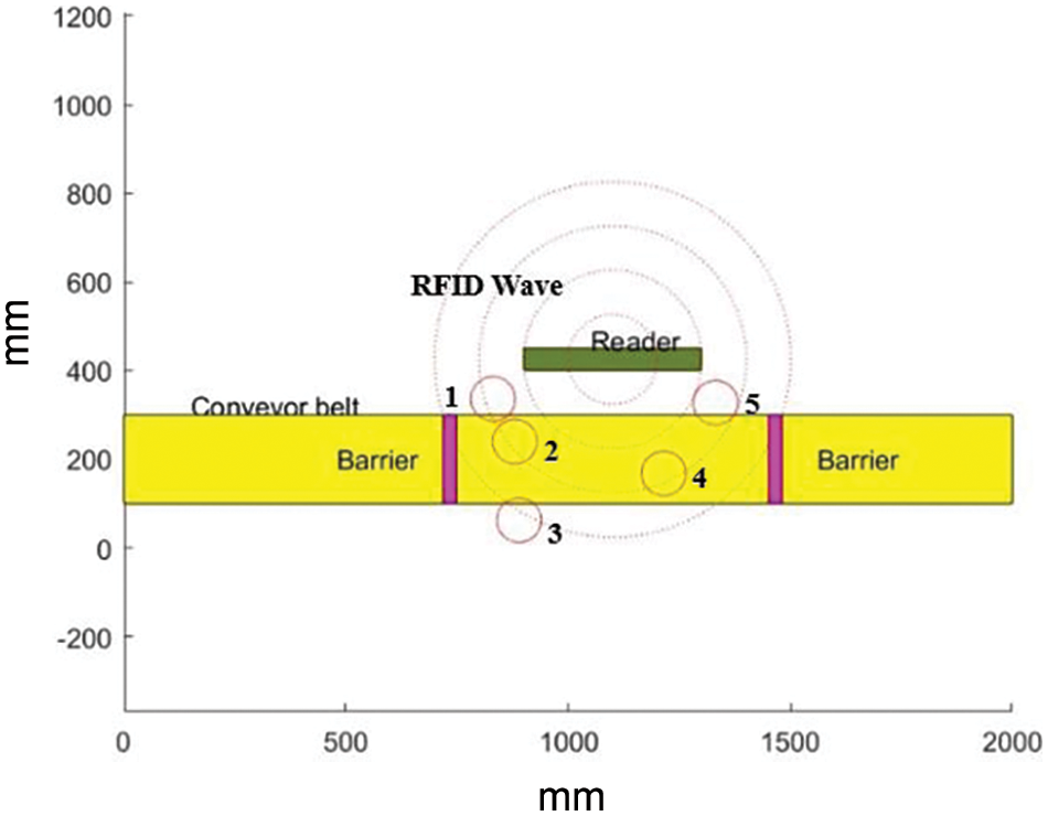
Figure 8: Simulation of the proposed RFID checkout system using a conveyor, two barriers, and one reader with five tags
In the simulation, the results are obtained in three stages, as depicted in Fig. 9. In the initial stage, the tags of unscanned items are marked in green, as shown in Fig. 9a. This signifies that these items have not been detected by the RFID system. In the second stage, RFID waves are emitted and scan the tags, resulting in all tags within range being marked in red, as shown in Fig. 9b. This includes items that are not on the conveyor belt and are causing interference to the system, leading to detection errors. In the final stage, the laser simulator logic algorithm is applied, acting as an AI basket to categorize objects as either desired or undesired (noise) objects. The desired objects remain marked in red, while noise objects are once again marked in green, as shown in Fig. 9c. This aids in distinguishing between items that should be scanned and those that should be disregarded by the system.
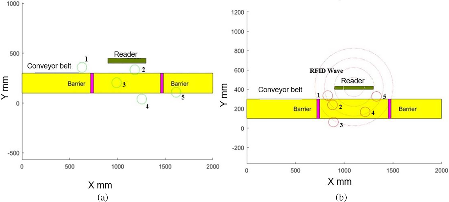
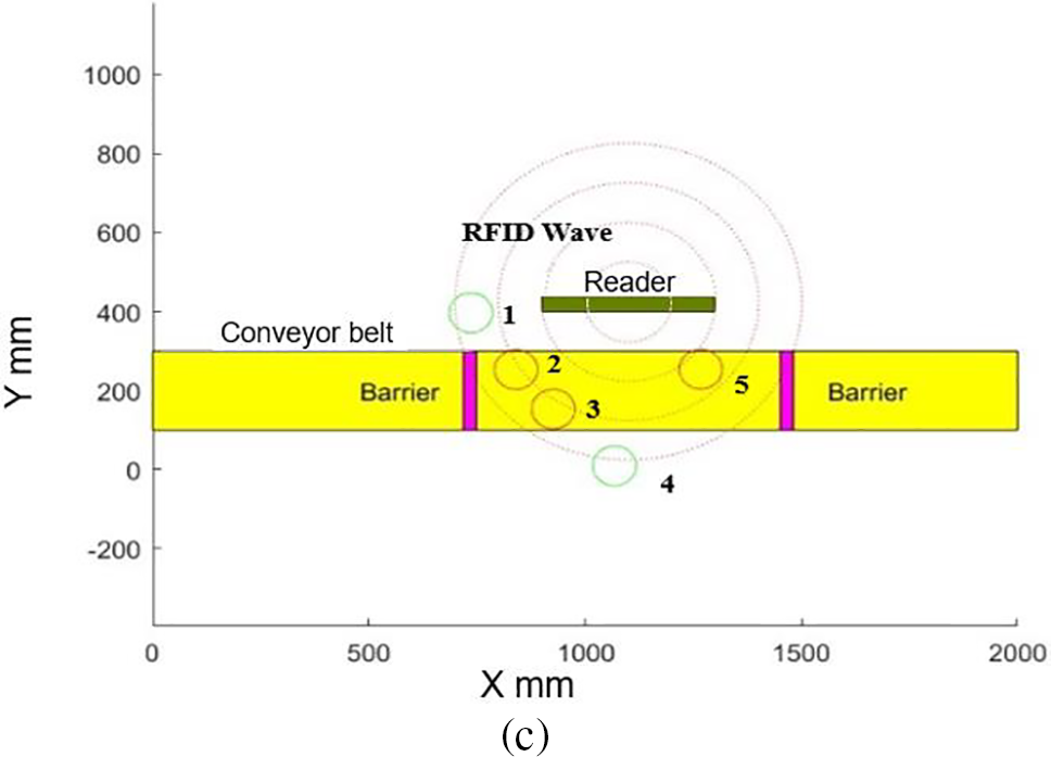
Figure 9: Status of checkout system: (a) Checkout system before wave RFID generation (b) Checkout system after wave generation and before laser simulator logic system (c) Checkout system after laser simulator logic system
Table 4 compares the decision-making process between fuzzy logic and laser simulator logic in scenarios with low overlapping between linguistic variables. It covers a broad spectrum of crisp inputs chosen to encompass all possible input scenarios. The crisp outputs are calculated using both fuzzy logic and laser simulator logic algorithms memberships and rules, as detailed in Section 2.
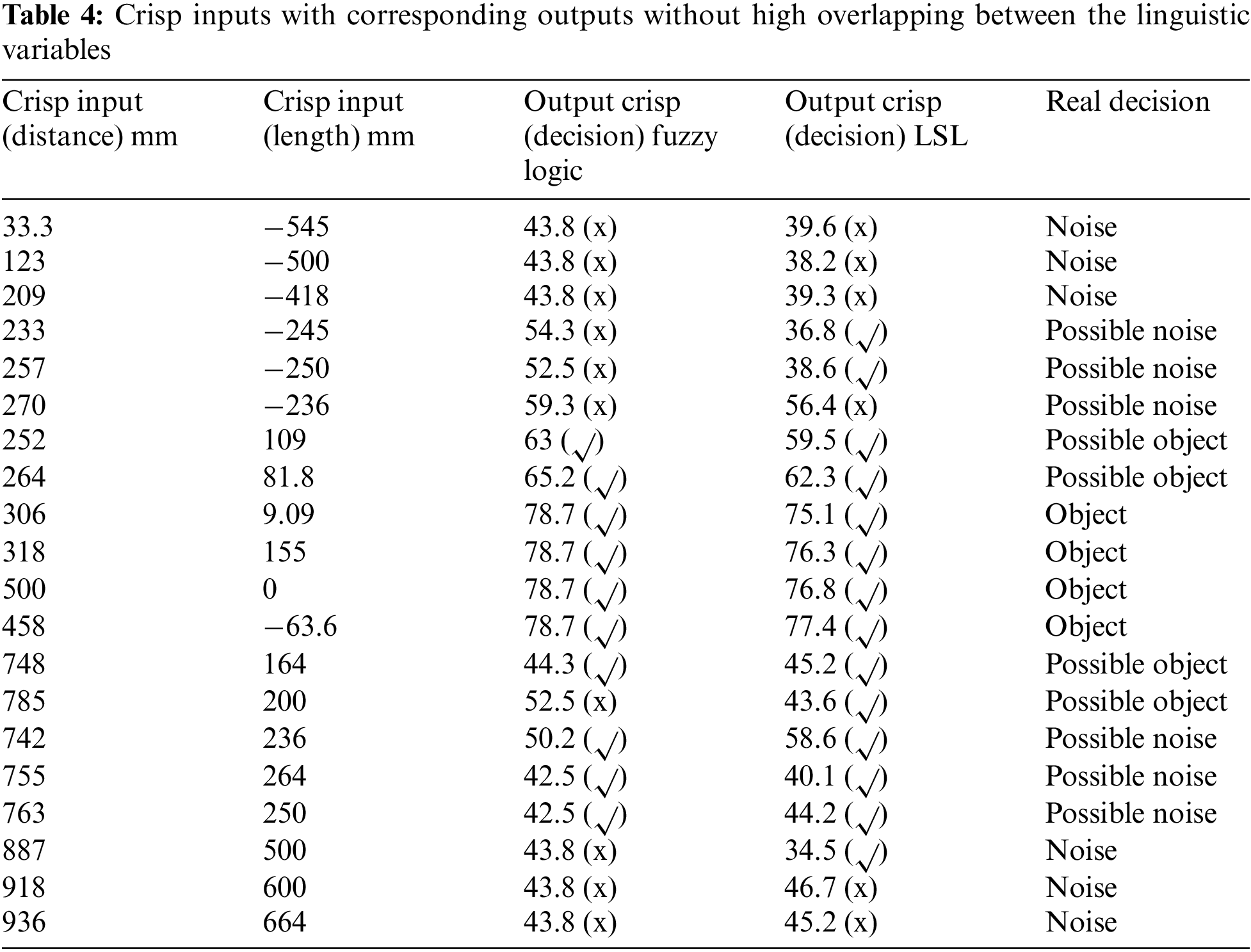
Both fuzzy logic and laser simulator algorithms were compared with the actual real decision, as summarised in Table 4. It is evident that fuzzy logic has inaccurately determined the correct decision in 9 out of 20 cases, resulting in a 45% error rate. This can be attributed to the low overlap between linguistic variables and the significant noise affecting the RFID system. Conversely, laser simulator logic has made incorrect decisions in 7 out of 20 cases, yielding a 35% error rate, also due to the consideration of low overlap between linguistic variables. In scenarios involving noise-related decisions, both fuzzy logic and laser simulator logic exhibit vulnerabilities, with laser simulator logic demonstrating superior performance.
Table 5 compares the decision-making process between fuzzy logic and laser simulator logic in scenarios with high overlapping between linguistic variables. It encompasses a broad range of crisp inputs specifically chosen to incorporate all possible input scenarios in a high overlapping case. Similar to Table 4, the crisp outputs are computed using both fuzzy logic and laser simulator logic algorithms’ memberships and rules, as detailed in Section 2, with the real decisions listed in the last column.
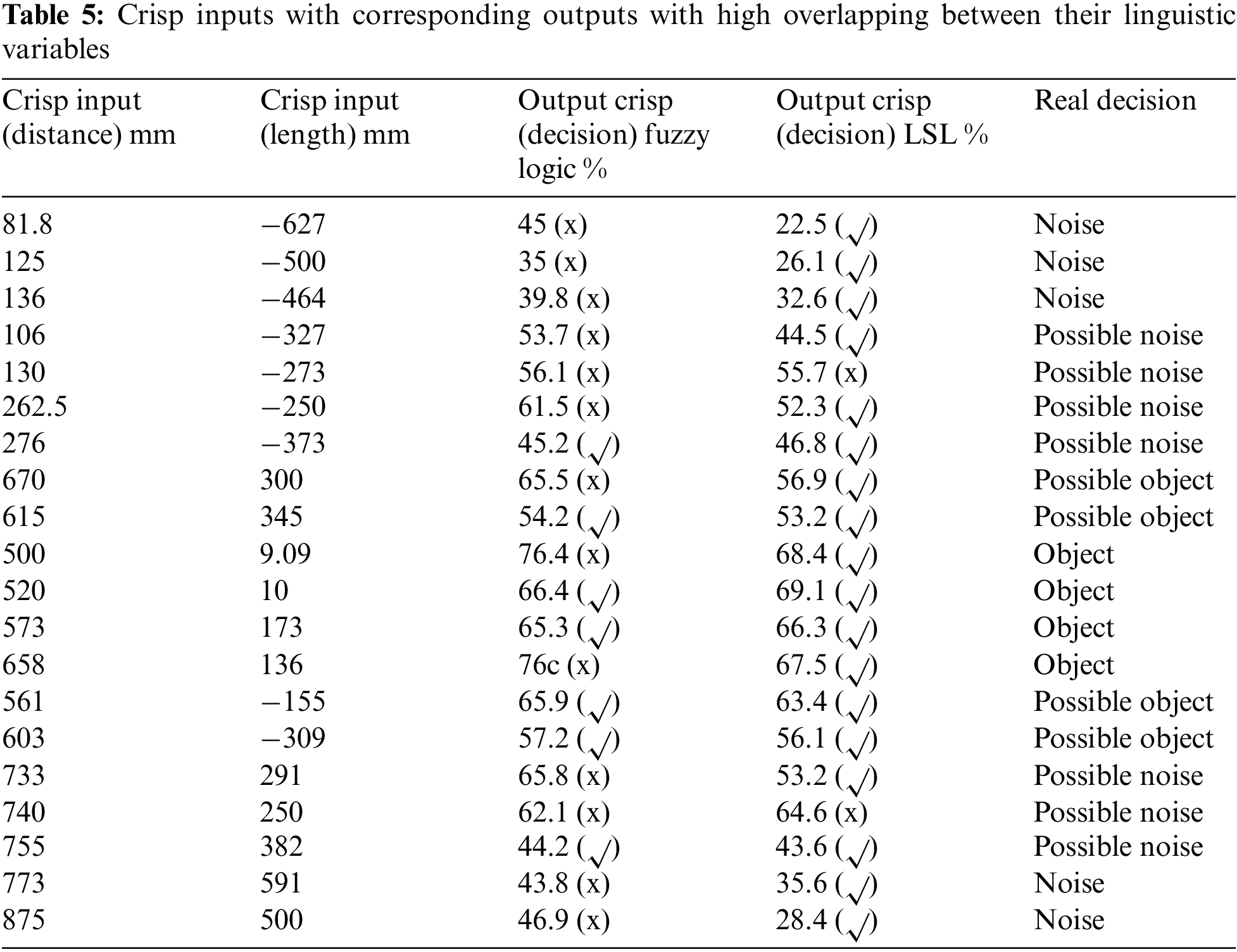
From Table 5, it is evident that fuzzy logic has made incorrect decisions in 13 out of 20 cases, resulting in a 65% error rate. This is attributed to fuzzy logic’s inability to handle high overlap between linguistic variables. In contrast, laser simulator logic has only failed in 2 out of 20 cases, with a 10% error rate, showcasing its capability to manage high overlap between linguistic variables effectively. Therefore, it can be concluded that the laser simulator is highly effective in eliminating noise in the checkout RFID system.
2.3 Experimental Work for Smart Checkout System
A small-scale prototype has been developed to test the proposed noise removal with the RFID system. In this experimental work, the focus will solely be on the high overlapping case using laser simulator logic, as it shows promising results compared to fuzzy logic as discussed in Section 2.2.2. This prototype, named AI RFID basket, will be compared with a standard RFID basket as outlined below:
2.3.1 Experimental Setup of Smart Checkout System
The experimental setup for this study comprises three main components: an Arduino board, an RFID reader, and RFID tags. The Arduino board serves as the microcontroller platform, responsible for controlling and coordinating the various components of the system. It is connected to a computer via a USB cable for programming and power supply purposes. The RFID reader is utilized to scan the unique identification codes stored on the RFID tags attached to the items being processed at checkout. This module is linked to the Arduino board through digital pins, as shown in Fig. 10.
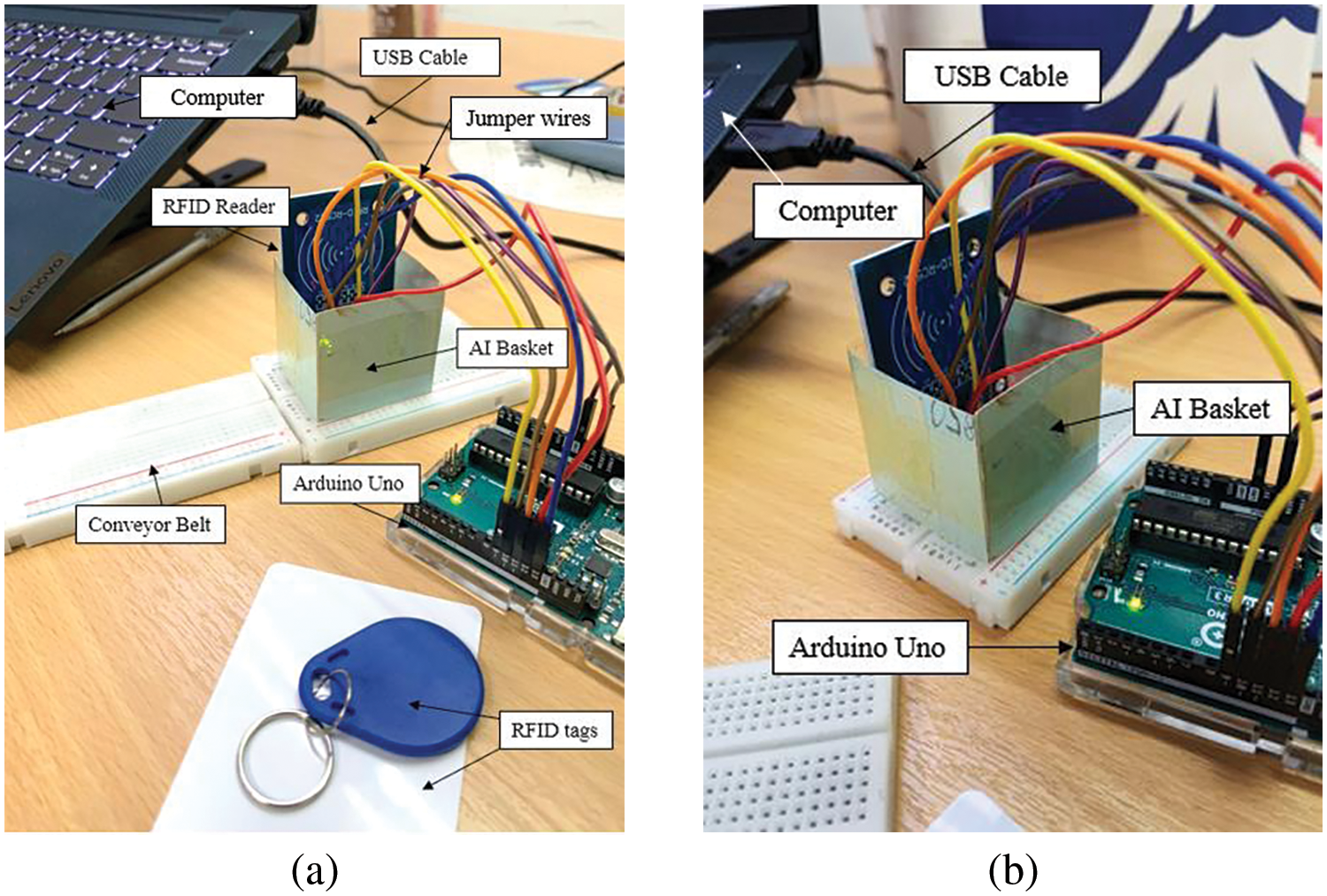
Figure 10: Experimental setup: (a) Components of the experimental work (b) Connection of the Arduino Uno to the reader and computer
The Arduino Integrated Development Environment (IDE) is utilized to develop the RFID program on a computer. This software application enables the creation, debugging, and uploading of sketches (programs) to an Arduino board. To create the RFID program, a suitable is selected within the Arduino IDE. This sketch includes the essential code for interfacing with the RFID reader module and reading the unique identification codes stored on the RFID tags. Subsequently, the sketch is compiled and uploaded to the Arduino board via a USB cable that connects both the computer and the board.
Fig. 11a shows an RFID reader integrated with an AI basket prototype. The results of the RFID reading process can be monitored by accessing the serial monitor within the Arduino IDE. In this setup, it displays information related to any detected RFID tag when identified by the RFID reader module. During the testing the prototype system, an RFID tag or card is positioned near the RFID reader. In this experimental configuration, RFID tags are used to represent items, as depicted in Fig. 11b. Upon tag detection, the Arduino processes the data, which can then be viewed through the serial monitor.
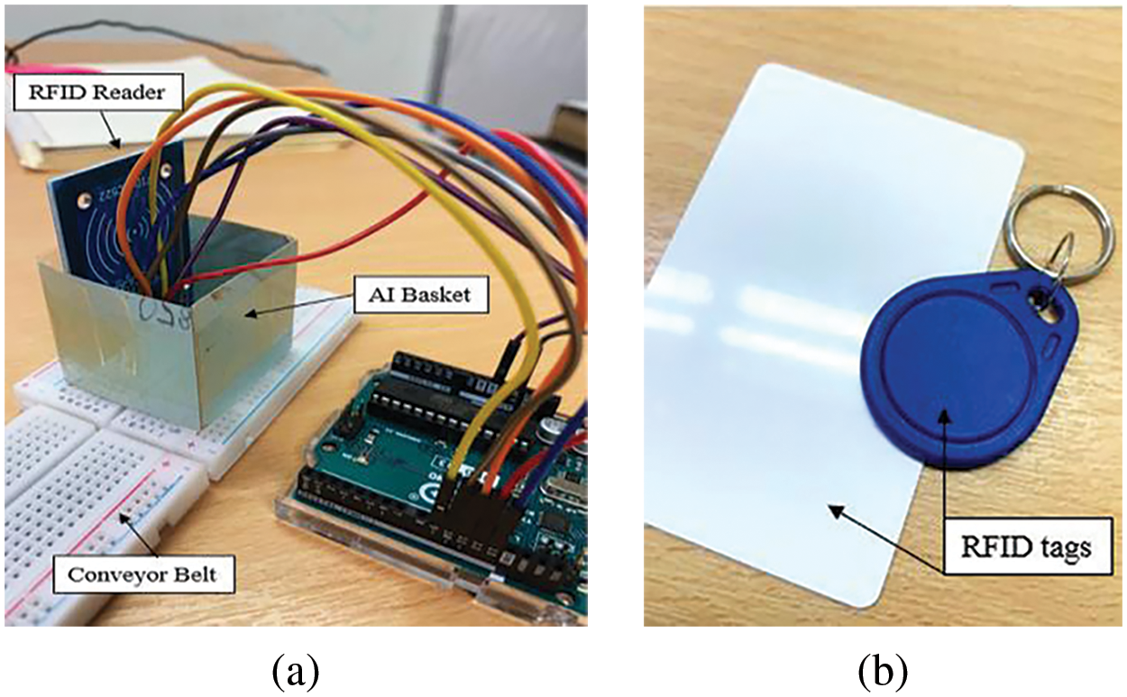
Figure 11: RFID system (a) RFID reader integrated with an AI basket prototype (b) RFID tags that represent items
In the third scenario, both tags were located outside of the AI basket, and neither of them could be reliably detected by the reader due to their distances falling beyond the reader’s range for accurate detection, as depicted in Fig. 12.
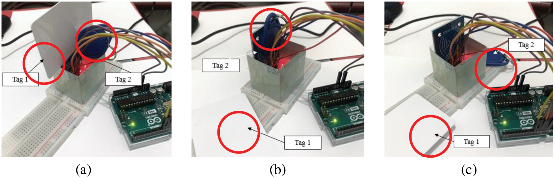
Figure 12: Tag placement in AI basket: (a) Both tags placed inside the AI basket (b) One tag inside, and one tag outside the AI basket (c) Both tags outside the AI basket
After setting up and connecting the system, two tags were employed to examine the proposed smart RFID system in item detection. Throughout the experimental phase, three distinct situations were encountered.
– In the first scenario, both tags were placed inside an AI basket that was positioned close to the RFID reader. The RFID reader was able to successfully read both tags in this scenario, as shown in Fig. 12a.
– In the second scenario, one tag was inside the AI basket while the other tag was positioned outside of it. The tag inside the AI basket could be read by the RFID reader, but the tag outside the AI basket may not have been within the reader’s detection range, as illustrated in Fig. 12b.
– In the third scenario, both tags were located outside of the AI basket, and neither of them could be reliably detected by the reader due to their distances falling beyond the reader’s range for accurate detection, as depicted in Fig. 12c.
The evaluation of the laser simulator logic algorithm in the AI basket is conducted as follows:
The positions of the tags are depicted in Fig. 13, with their locations denoted in terms of (X, Y)/(distance, length) coordinates, indicating the distance from the RFID reader and the length of the conveyor belt in millimetres (mm). These coordinates provide an accurate representation of the tags’ specific locations relative to the RFID reader and AI basket.
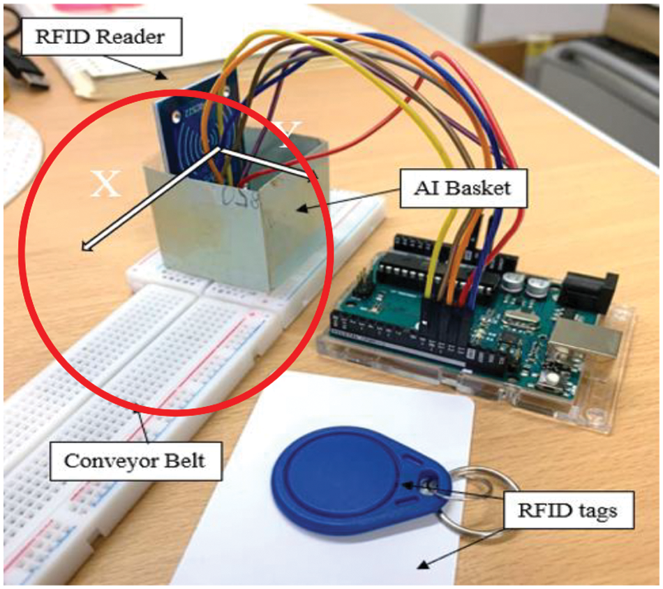
Figure 13: Positions of the tags in terms of (X, Y)/(length, distance)
In the first scenario, the tags are positioned within the AI basket area, which is located within a range of 55 mm from the RFID reader and at a length of 150 mm. Six experiments have been conducted for the smart RFID system with two tags, resulting in a total of 12 readings. Various positions for the two tags within different RFID reader ranges and lengths have been tested, as shown in Table 6. These locations were chosen to encompass all possible tag positions within AI basket, allowing for the evaluation of the proposed system under various conditions.
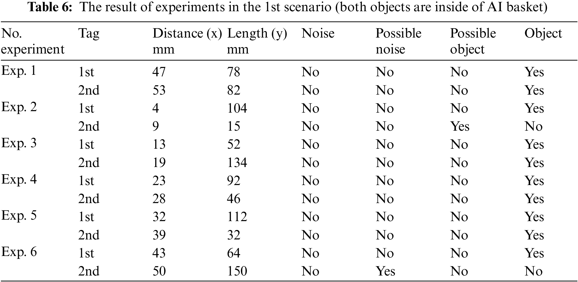
Table 6 displays the results of the tag readings by the RFID reader in the 1st scenario.
According to Table 6, it is evident that the RFID reader has successfully read the tags within the AI basket area in 10 out of 12 total readings, achieving a success rate of 83%. Due to their positions, two recording errors occurred when the tags are positioned at the border of AI basket, near the side of the reader (resulting in a possible object decision), and at the opposite border, far from the reader’s side, where they are classified as noise.
Similarly, in the second scenario, six experiments were conducted to assess the locations of the two tags, with one indie and the other outside of the AI basket. A total of 12 readings for the two tags were recorded and analyzed, as presented in Table 7. The tag locations encompassed a wide ranges of distances and lengths from the reader.
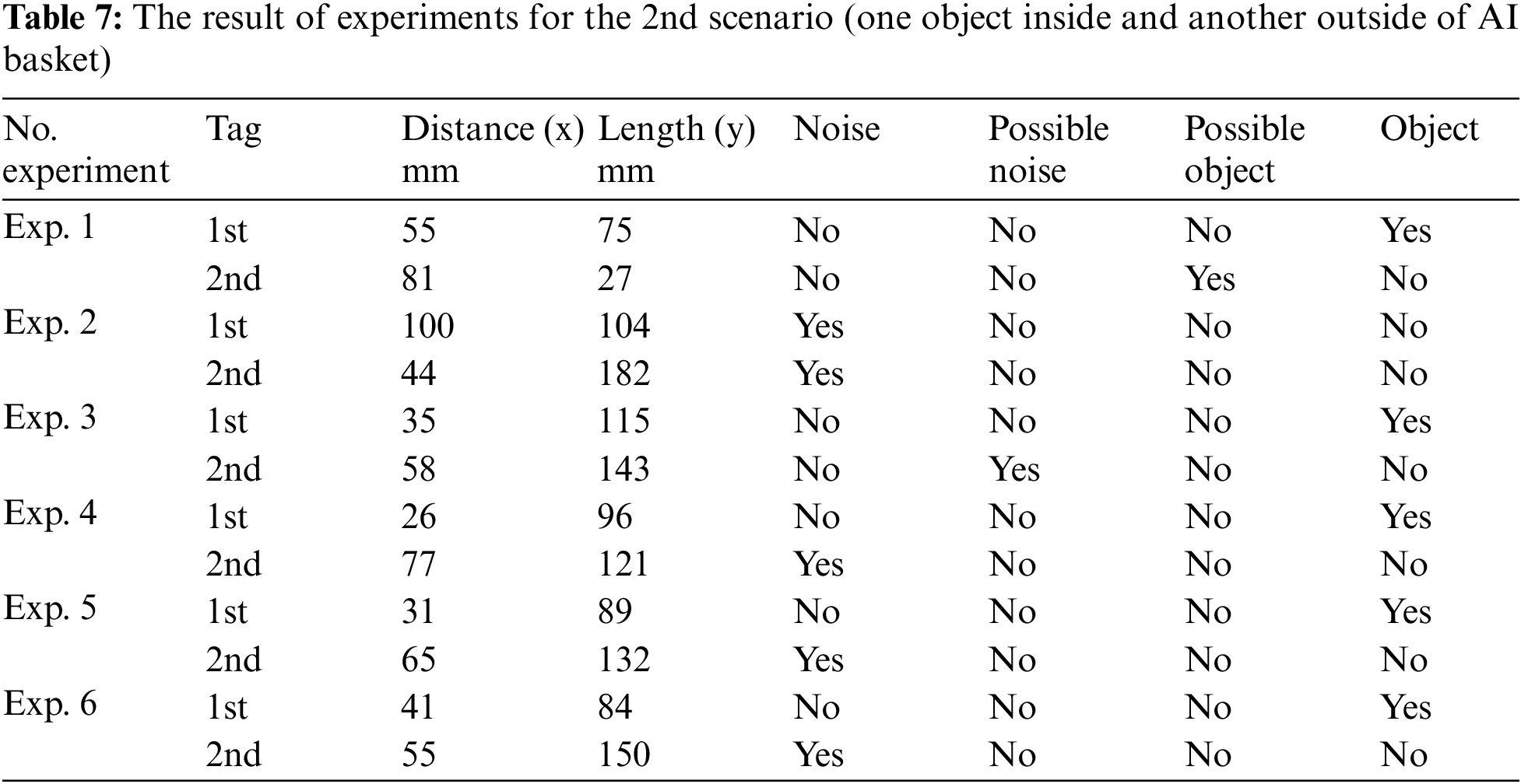
In Table 7, the correct classification of tags into either objects or noise is achieved in approximately 11 out of 12, resulting in a success rate of 91%. It is noted that in experiment 3, the decision for the 2nd tag is possible noise, which can be identified as noise. However, an incorrect decision occurred with the 2nd tag in the first experiment, where it was classified as a possible object instead of noise or potential noise.
The third scenario is performed to evalaute the capability of the system to classify objects located outside of the AI basket. Six experiments were conducted with numerous values for reader range and length, and the results presented in Table 8.
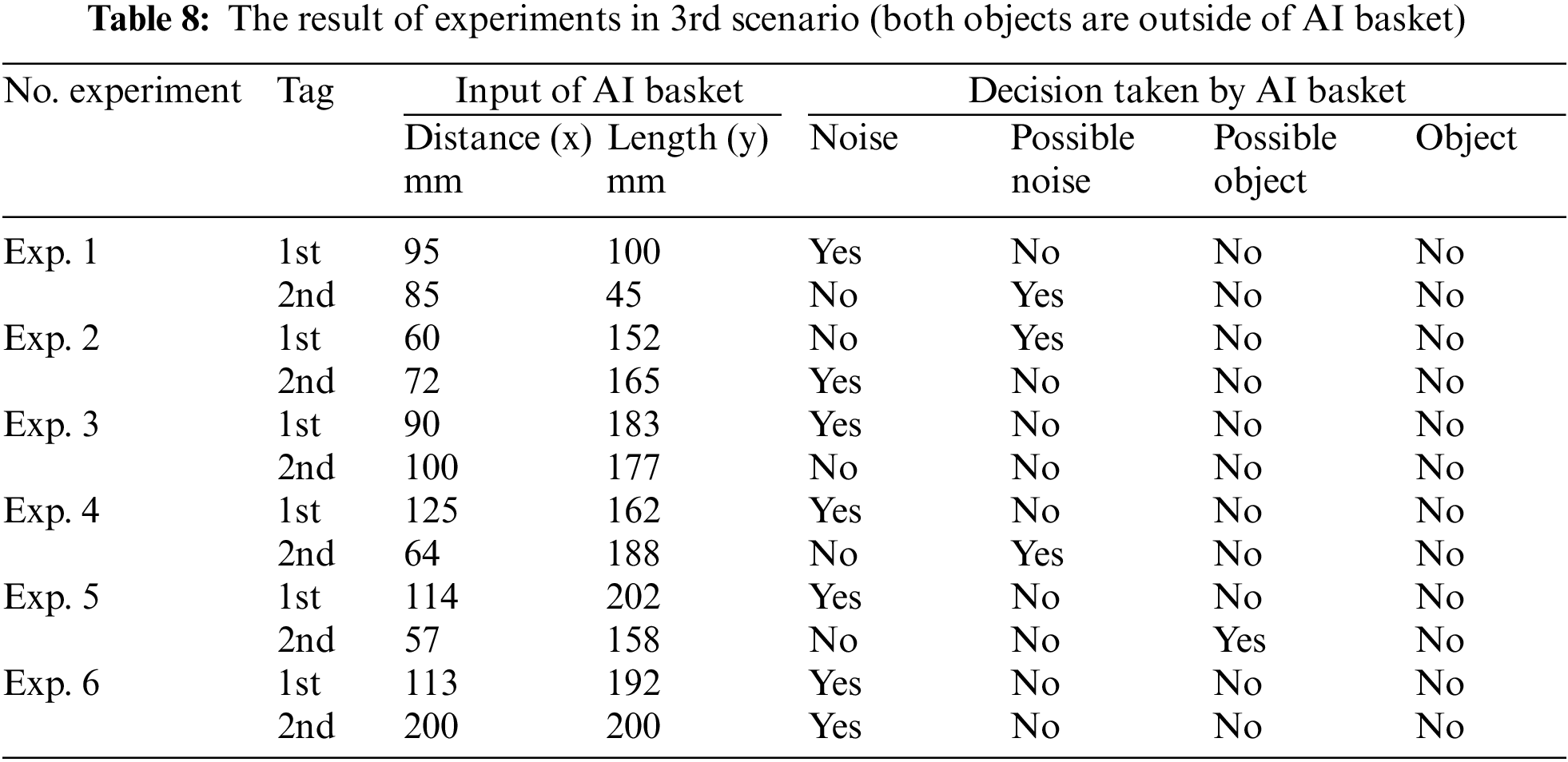
As shown in Table 8, the system demonstrated correct classification in 11 out of 12 instances, achieving a success rate of 91%. The possible noise decision is considered correct, as it is approximately noise. However, an incorrect decision occurred with the 2nd tag in experiment 3, where the distance and length were at the borders of the AI basket.
Observations from Tables 6–8 indicates that the accuracy of the system improves when the tag location is further from reader, or not at the border of AI basket. This explains why the success rate in Table 6 is lower compared to Tables 7 and 8. Consequently, the average success rate for all experiments across all these three tables is calculated at 88%.
The integration of RFID technology and the Improved Laser Simulator Logic (ILSL) algorithm in the development of a smart checkout system has significantly enhanced the retail stores checkout counters. This innovative solution has addressed the challenges of errors, noise, and inefficiencies associated with conventional checkout processes. The real-time identification and tracking of items through RFID technology can minimize manual entry errors and barcode scanning time. The rapid and seamless item detection using RFID tags attached to products can lead to a more streamlined and efficient checkout experience for both customers and employees. The accuracy of the proposed smart RFID system for item detection has been validated through simulation and experimental tests using MATLAB and a small-scale prototype, ensuring that the relevant items are distinguished from other non-relevant objects. The decision-making process is facilitated by a novel algorithm called improved laser simulator logic, which enables the system to accurately recognize and process the items within the AI basket. In conclusion, the smart checkout system utilyzing RFID technology and the improved laser simulator logic algorithm has the potential to transform the retail stores checkout process by enhancing efficiency, accuracy, and convenience for both customers and businesses. The success of these proposed smart checkout system demonstrates the potential for RFID-based smart checkout systems to improve the overall shopping experience and address the challenges faced by traditional barcode and existing RFID-based systems.
Acknowledgement: Authors would like to thank Universiti Malaya and Ministry of High Education-Malaysia for supporting this work under Research Grant FRGS/1/2023/TK10/UM/02/3 and GPF 020A-2023. The authors would also like to extend their appreciation to King Saud University for funding this project through the Researchers Supporting Project Number (RSPD2024 R803), King Saud University, Riyadh, Saudi Arabia. The authors would also thank Alfaisal University for supporting this project.
Funding Statement: This project receives a funding from Universiti Malaya and Ministry of High Education-Malaysia under Research Grant FRGS/1/2023/TK10/UM/02/3 and GPF 020A-2023. This research was also supported by Researchers Supporting Project Number (RSPD2024 R803), King Saud University, Riyadh, Saudi Arabia. It is also supported by Alfaisal Universiy.
Author Contributions: Shazielya Shamsul: Conceptualization, Formal Analysis, Methodology and Writing–Original Draft preparation. Mohammed A. H. Ali: Conceptualization, Formal Analysis, Methodology, Data Curation, Supervision, Writing–Review & Editing, Funding Acquisition and Project Administration. Salwa Hanim Abdul-Rashid: Supervision, Writing–Review & Editing and Project Administration. Atef M. Ghaleb: Review & Editing and Proofreading. Fahad M. Alqahtani: Review & Editing and Proofreading. All authors reviewed the results and approved the final version of the manuscript.
Availability of Data and Materials: No available data.
Conflicts of Interest: The authors declare that they have no conflicts of interest to report regarding the present study.
References
1. Y. W. Chang and J. Chen, “What motivates customers to shop in smart shops? The impacts of smart technology and technology readiness,” J. Retailing Consum. Serv., vol. 58, no. 3, pp. 102325, Jan. 2021. doi: 10.1016/j.jretconser.2020.102325. [Google Scholar] [CrossRef]
2. Y. J. Tu, W. Zhou, and S. Piramuthu, “Critical risk considerations in auto-ID security: Barcode vs. RFID,” Decis. Support Syst., vol. 142, pp. 113471, Mar. 2020. doi: 10.1016/j.dss.2020.113471. [Google Scholar] [CrossRef]
3. S. Gayathri, K. Jeyapiriya, K. Jeyaprakash, and K. Lalitha, “Detection and identification of things for blind people using raspberry PI,” in Proc. 2021 4th Int. Conf. Comput. Commun. Technol., ICCCT 2021, Institute of Electrical and Electronics Engineers Inc., 2021, pp. 194–196. [Google Scholar]
4. R. Abreo, B. Dsouza, H. Patil, D. Varghese, and A. Tripathy, “Smart shopping system with android application and integrated billing,” in Proc. Int. Conf. Recent Adv. Comput. Tech. (IC-RACT), 2020. [Google Scholar]
5. D. Sinha, K. Cottur, K. Bhat, C. Guruprasad, and B. Nath, “Automated billing system using RFID and cloud,” in 2019 Innov. Power Adv. Comput. Technol. (i-PACT), Vellore, India, 2019, pp. 1–6. [Google Scholar]
6. S. Praveen, V. Pugalenthiran, and K. Jaraline Kirubavathy, “Voice controlled shopping trolley navigation with RFID scanner and live billing using IoT,” J. Physics: Conf. Series, vol. 2040, no. 2021, pp. 1–10, 2021. [Google Scholar]
7. M. Ahmad, M. A. Abdul Karim, and M. H. A. Zaidi, “RFID application in courier services,” IJPCC, vol. 7, no. 1, pp. 108–112, Jul. 2021. [Google Scholar]
8. F. Nisha, “Implementation of RFID technology at defence science library, DESIDOC: A case study,” DESIDOC J. Libr. Inf. Technol., vol. 38, no. 1, pp. 27–33, 2018. doi: 10.14429/djlit.38.1.12351. [Google Scholar] [CrossRef]
9. S. Paaske, A. Bauer, T. Moser, and C. Seckman, “The benefits and barriers to RFID technology in healthcare,” On-Line J. Nurs. Inform., vol. 21, no. 2, 2017. [Google Scholar]
10. M. Aboelmaged and G. Hashem, “RFID application in patient and medical asset operations management: A technology, organizational and environmental (TOE) perspective into key enablers and impediments,” Int. J. Med. Inform., vol. 118, no. 2006, pp. 58–64, 2018. doi: 10.1016/j.ijmedinf.2018.07.009. [Google Scholar] [PubMed] [CrossRef]
11. M. Golsorkhtabaramiri and N. Issazadehkojidi, “A distance based RFID reader collision avoidance protocol for dense reader environments,” Wirel. Pers. Commun., vol. 95, no. 2, pp. 1781–1798, 2017. doi: 10.1007/s11277-016-3918-0. [Google Scholar] [CrossRef]
12. A. Kumar, A. Aggarwal, and K. Gopal, “A novel and efficient reader-to-reader and tag-to-tag anti-collision protocol,” IETE J. Res., vol. 67, no. 3, pp. 301–312, 2021. doi: 10.1080/03772063.2018.1537815. [Google Scholar] [CrossRef]
13. T. Athauda and N. C. Karmakar, “The realization of chipless RFID resonator for multiple physical parameter sensing,” IEEE Internet Things J., vol. 6, no. 3, pp. 5387–5396, 2019. doi: 10.1109/JIOT.2019.2901470. [Google Scholar] [CrossRef]
14. S. Taoufik, P. Dherbecourt, A. El Oualkadi, and F. Temcamani, “Reliability and failure analysis of UHF RFID passive tags under thermal storage,” IEEE Trans. Device Mater. Reliab., vol. 17, no. 3, pp. 531–538, 2017. doi: 10.1109/TDMR.2017.2733519. [Google Scholar] [CrossRef]
15. W. H. Zhou, N. D. Jiang, and C. C. Yan, “Research on anti-collision algorithm of RFID tags in logistics System,” Proc. Comput. Sci., vol. 154, no. 1, pp. 460–467, 2018. doi: 10.1016/j.procs.2019.06.065. [Google Scholar] [CrossRef]
16. K. Pal, “A novel frame-slotted ALOHA algorithm for radio frequency identification system in supply chain management,” Proc. Comput. Sci., vol. 184, no. 2, pp. 871–876, 2021. doi: 10.1016/j.procs.2021.03.110. [Google Scholar] [CrossRef]
17. J. Xiang, A. Zhao, G. Y. Tian, W. Woo, L. Liu and H. Li, “Prospective RFID sensors for the IoT healthcare system,” J. Sens., vol. 2022, no. 9, pp. 1–19, 2022. doi: 10.1155/2022/8787275. [Google Scholar] [CrossRef]
18. A. Abugabah, N. Nizamuddin, and A. Abuqabbeh, “A review of challenges and barriers implementing RFID technology in the healthcare sector,” Proc. Comput. Sci., vol. 170, no. 3, pp. 1003–1010, 2020. doi: 10.1016/j.procs.2020.03.094. [Google Scholar] [CrossRef]
19. M. Shokouhifar, “Swarm intelligence RFID network planning using multi-antenna readers for asset tracking in hospital environments,” Comput. Netw., vol. 198, no. 1, pp. 108427, 2021. doi: 10.1016/j.comnet.2021.108427. [Google Scholar] [CrossRef]
20. S. Karuppuswami, L. Matta, E. Alocilja, and P. Chahal, “A wireless RFID compatible sensor tag using gold nanoparticle markers for pathogen detection in the liquid food supply chain,” IEEE Sens. Lett., vol. 2, no. 2, pp. 1–4, 2018. doi: 10.1109/LSENS.2018.2822305. [Google Scholar] [CrossRef]
21. S. Nitin Shah and A. Abuzneid, “IoT based smart attendance system (SAS) using RFID,” in 2019 IEEE Long Island Syst., Appl. Technol. Conf. (LISAT), 2019. [Google Scholar]
22. J. Su, Z. Sheng, A. X. Liu, Z. Fu, and C. Huang, “An efficient missing tag identification approach in RFID collisions,” IEEE Trans. Mob. Comput., vol. 22, no. 2, pp. 720–731, 2023. doi: 10.1109/TMC.2021.3085820. [Google Scholar] [CrossRef]
23. F. Bibi, C. Guillaume, N. Gontard, and B. Sorli, “A review: RFID technology having sensing aptitudes for food industry and their contribution to tracking and monitoring of food products,” Trends Food Sci. Technol., vol. 62, no. 4, pp. 91–103, 2017. doi: 10.1016/j.tifs.2017.01.013. [Google Scholar] [CrossRef]
24. M. Beqqal and M. Azizi, “Classification of major security attacks against RFID systems,” in Proc. 2017 Int. Conf. Wirel. Technol., Embedded Intell. Syst., Fez, Morocco, IEEE, 2017. [Google Scholar]
25. J. Aliasgari, M. Forouzandeh, and N. Karmakar, “Chipless RFID readers for frequency-coded tags: Time-domain or frequency-domain?,” IEEE J. Radio Freq. Identif., vol. 4, no. 2, pp. 146–158, 2020. doi: 10.1109/JRFID.2020.2982822. [Google Scholar] [CrossRef]
26. L. Shen, Q. Zhang, J. Pang, H. Xu, and P. Li, “PRDL: Relative localization method of RFID tags via phase and RSSI based on deep learning,” IEEE Access, vol. 7, pp. 20249–20261, 2019. doi: 10.1109/ACCESS.2019.2895129. [Google Scholar] [CrossRef]
27. A. D. Landmark and B. Sjobakk, “Tracking customer behavior in fashion retail using RFID,” Int. J. Retail Distrib. Manag., vol. 45, no. 7–8, pp. 844–858, 2017. doi: 10.1108/IJRDM-10-2016-0174. [Google Scholar] [CrossRef]
28. J. Feng, F. Li, C. Xu, and R. Y. Zhong, “Data-driven analysis for RFID-enabled smart factory: A case study,” IEEE Trans. Syst. Man. Cybern.: Syst., vol. 50, no. 1, pp. 81–88, 2020. doi: 10.1109/TSMC.2018.2882838. [Google Scholar] [CrossRef]
29. M. A. H. Ali, S. Mekhilef, N. Yusoff, and B. Abd Razak, “Laser simulator logic: A novel inference system for highly overlapping of lingeustic variable in membership functions,” J. King Saud Univ. Comput. Inf. Sci., vol. 34, no. 10, pp. 8019–8040, 2022. doi: 10.1016/j.jksuci.2022.07.017. [Google Scholar] [CrossRef]
Cite This Article
 Copyright © 2024 The Author(s). Published by Tech Science Press.
This work is licensed under a Creative Commons Attribution 4.0 International License , which permits unrestricted use, distribution, and reproduction in any medium, provided the original work is properly cited.
 Downloads
 Citation Tools