
 Submit a Paper
 Propose a Special lssue
 Open Access
ARTICLE

Investigation of Inside-Out Tracking Methods for Six Degrees of Freedom Pose Estimation of a Smartphone in Augmented Reality
1 Graduate School of Engineering, The University of Tokyo, Tokyo, 113-0033, Japan
2 Information Technology Center, The University of Tokyo, Chiba, 277-0882, Japan
* Corresponding Author: Takefumi Ogawa. Email:
(This article belongs to the Special Issue: Advances and Applications in Signal, Image and Video Processing)
Computers, Materials & Continua 2024, 79(2), 3047-3065. https://doi.org/10.32604/cmc.2024.048901
Received 21 December 2023; Accepted 09 April 2024; Issue published 15 May 2024
 View Full Text
 Download PDF
Abstract
Six degrees of freedom (6DoF) input interfaces are essential for manipulating virtual objects through translation or rotation in three-dimensional (3D) space. A traditional outside-in tracking controller requires the installation of expensive hardware in advance. While inside-out tracking controllers have been proposed, they often suffer from limitations such as interaction limited to the tracking range of the sensor (e.g., a sensor on the head-mounted display (HMD)) or the need for pose value modification to function as an input interface (e.g., a sensor on the controller). This study investigates 6DoF pose estimation methods without restricting the tracking range, using a smartphone as a controller in augmented reality (AR) environments. Our approach involves proposing methods for estimating the initial pose of the controller and correcting the pose using an inside-out tracking approach. In addition, seven pose estimation algorithms were presented as candidates depending on the tracking range of the device sensor, the tracking method (e.g., marker recognition, visual-inertial odometry (VIO)), and whether modification of the initial pose is necessary. Through two experiments (discrete and continuous data), the performance of the algorithms was evaluated. The results demonstrate enhanced final pose accuracy achieved by correcting the initial pose. Furthermore, the importance of selecting the tracking algorithm based on the tracking range of the devices and the actual input value of the 3D interaction was emphasized.Keywords
Augmented reality and virtual reality (AR/VR) technology have been propelled by improvements in both hardware and software performance. Numerous systems for experiencing three-dimensional (3D) content, such as HTC VIVE [1], HoloLens [2] and Meta Quest [3] are now commercially available. These systems typically include a head-mounted display (HMD) presenting a virtual space or virtual objects, accompanied by a controller that serves as a six degrees of freedom (6DoF) input interface to facilitate 3D interaction. In systems such as HTC VIVE [1], the HMD and controller are tracked using an external base station (sensor) in the surrounding environment employing an outside-in tracking method. However, challenges arise when the HMD or controller moves out of the tracking range or is obstructed, leading to difficulties in estimating their poses. Conversely, systems such as Meta Quest [3] use a camera (sensor) on the HMD to scan the real environment and estimate the pose of the HMD. The HMD camera also tracks the controller by employing an inside-out tracking approach. While this eliminates the need for an external sensor, the controller’s pose estimation is limited to the sensing range of the HMD.
Simultaneously, there is a rising trend in AR/VR libraries to facilitate the use of smartphones as display devices, such as ARCore [4], ARKit [5] and Google Cardboard [6]. AR experiences are becoming more widespread, and smartphones, being universal devices capable of self-pose estimation, have inspired research [7–9]. In researches [7–9], a smartphone was used as an input controller for 3D interactions, but the selection of tracking algorithm was insufficiently reviewed.
This study focuses on using a smartphone as a controller for 3D interaction in an AR environment. The primary goal of this study is to explore pose estimation methods that eliminate the limitations posed by sensors traditionally used for device tracking. Fig. 1 illustrates the conceptual framework of this study, and the key contributions are outlined as follows.
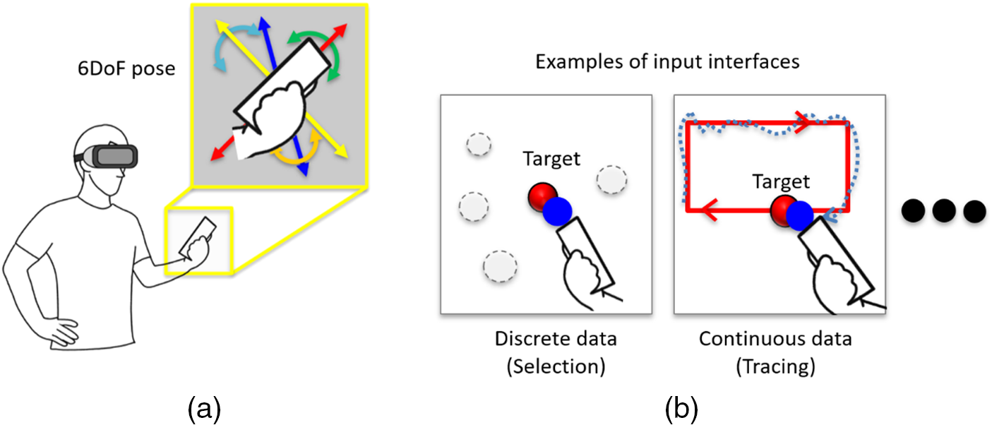
Figure 1: Concept of this study: (a) smartphone controller based on six degrees of freedom (6DoF) pose for three-dimensional (3D) interaction (b) examples of input interfaces using smartphones
1. Inside-out tracking methods that estimate the 6DoF pose of the controller were proposed using only the HMD and the controller (smartphone) (Fig. 1a). In particular, the pose can be continuously estimated without being affected by the sensing area of the devices.
2. Computer vision-based tracking approaches, including marker recognition and visual-inertial odometry (VIO), were investigated. This involves estimating the pose of the controller in the HMD coordinate system and correcting the estimated pose.
3. Seven tracking algorithms are presented as potential solutions that combine various pose estimation and correction methods.
4. Guidelines are provided for selecting an appropriate tracking algorithm, considering the controller’s interaction range (within or outside the field of view of (FoV) of HMD’s camera) and actual input values (discrete or continuous data (Fig. 1b)) required for a 6DoF input interface.
The subsequent section of this study is organized as follows: Section 2 introduces related work on tracking methods for 3D interactions, Section 3 describes the details of inside-out tracking methods for pose estimation, Section 4 describes experiments to evaluate the performance of pose estimation using the seven tracking algorithms, Section 5 discusses the pose estimation methods, and Section 6 provides the conclusion and future work.
Three primary methods of tracking for 3D interaction are shown in Fig. 2: (a) outside-in tracking, (b) inside-out tracking using the sensor of the HMD, and (c) inside-out tracking using the sensor of the controller. In this section, tracking methods are categorized into (1) pose tracking that does not use the controller’s sensor (Figs. 2a or 2b) and (2) pose tracking that uses the controller’s sensor (Fig. 2c or a combination of Figs. 2b and 2c).
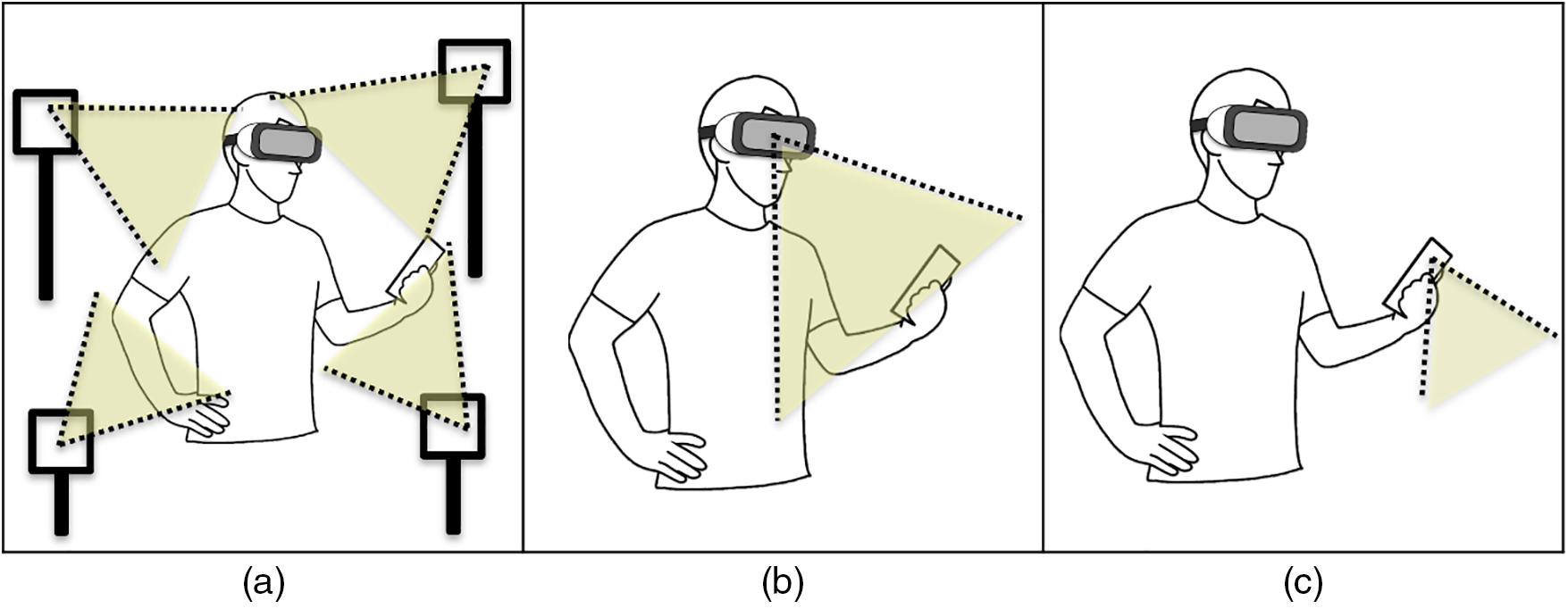
Figure 2: Tracking approaches for controller’s pose estimation: (a) outside-in tracking (b) inside-out tracking using head-mounted display (HMD) (c) inside-out tracking using a controller
2.1 Controller Pose Tracking for 3D Interactions
A crucial aspect of 3D interactions, such as selecting and moving virtual objects, is the 6DoF input interface. Numerous studies have used high-performance motion capture cameras [10] and standard input devices [1] for AR/VR (Fig. 2a). However, recognition is limited to the environment where the tracking sensor is installed [11], leading to high manufacturing costs [12]. In the case of commercial devices [3], the LED in the controller can be tracked by the HMD’s camera (Fig. 2b). Additionally, to use a smartphone as a controller, a marker can be displayed on the smartphone screen for pose estimation through marker recognition [13,14], often combined with touch input operations [15]. However, challenges arise when the controller is not within the camera’s view [3,13–15]. In addition, a natural user interface (NUI) can be achieved through hand skeleton extraction [16] and gesture recognition [17] without using a physical controller. However, issues such as user fatigue and the absence of tactile feedback are associated with the operation of moving hands in the air.
This study uses a smartphone as a controller due to its universal presence and user familiarity, coupled with the ability to provide haptic feedback. The smartphone’s capacity to estimate its pose using internal sensors enables 6DoF input even outside the HMD’s tracking range, thereby expanding the range of interaction.
2.2 Self-Tracking of Controller Pose Using Internal Sensors
Research [18] uses the smartphone’s built-in inertial measurement unit (IMU) sensor to estimate the device’s orientation (3DoF) and enables pointing operations through ray casting. Another study [19] used a device’s IMU sensor to achieve 3D rotation and translation of a virtual object. Here, a virtual plane corresponding to the mobile device is placed in 3D space, allowing 2D movement operation (parallel to the virtual plane) via slide input on the touchscreen. Rotating the device while pressing a physical button facilitates the rotation of the virtual plane. However, challenges in measurements using IMU sensors include the need to correct drift caused by cumulative errors [18], making it difficult to obtain accurate and continuous 6DoF values for determining position and orientation.
Within computer vision-based tracking methods, it is possible to estimate the device’s pose without visual markers, as illustrated in Fig. 2c. Techniques such as VIO [4,5], simultaneous localization and mapping (SLAM) [20], represent typical markerless methods and VR/AR applications are being realized using the above methods [21,22]. Some studies [7–9,23,24] have proposed using VIO (or SLAM) to enable 3D interaction over a wide range. For instance, research [23] proposes a 6DoF controller using SLAM by attaching a camera to a VR standard controller, automatically correcting sudden changes in pose due to tracking errors. However, these correction methods may not account for the impact of differences between the actual and estimated pose on the user, especially when the controller is within the HMD’s FoV. Recent advancements have enabled the independent estimation of a smartphone’s 6DoF pose, leading to research on using it as an input controller for large screen displays [7] or VR/AR applications [8,24]. In research [8], a virtual object corresponding to the smartphone’s pose is displayed in the HMD coordinate system, allowing the user to self-correct the pose. In addition, to use the smartphone’s pose estimated by VIO as input for ARHMD, research [9] recognizes the markers displayed on the smartphone screen with the HMD camera and converts the controller’s pose into the HMD coordinate system.
Our research aligns closely with previous researches [8,9] by proposing a method for estimating the controller’s pose and correcting them using an HMD and a controller. However, whereas researches [8,9] presented a single tracking algorithm combining a computer vision-based method and a correction method, how the tracking and correction methods were determined for each study is unknown. Our research proposed seven types of inside-out tracking algorithms that combine controller pose estimation methods and pose correction methods using an HMD and a controller (combination of Figs. 2b and 2c). In addition, guidelines for designing appropriate tracking algorithms were presented according to the interaction range of the controller and the pose-based actual input values.
3 Inside-Out Tracking-Based Pose Estimation
The system under consideration in this study comprises a display device (D-device) and a controller, as illustrated in Fig. 3. The D-device presents a 3D space to provide users with an AR/VR experience. Tracking is necessary when the controller is within the sensor range of the D-device. As described above, HMDs or mobile devices, such as smartphones and tablets, are mainly used as D-devices to estimate the pose of the D-device and controller. Furthermore, the controller (smartphone) serves as the input interface for operations on the D-device.
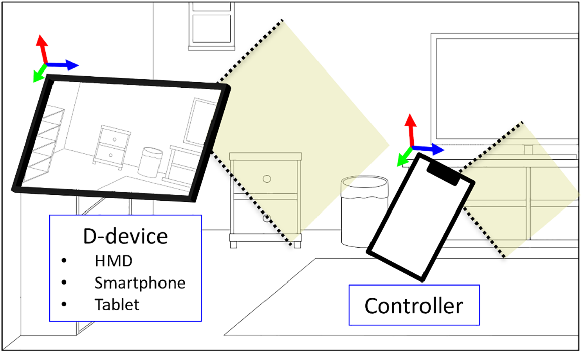
Figure 3: System configuration (Display device (D-device) and controller)
This study implemented a system using two smartphones (Samsung Galaxy S9 and S21) as the D-device and controller, similar to the studies [8,13]. However, the tracking algorithm for pose estimation outlined in Section 3 is applicable even in environments where HMDs serve as D-devices [9,14]. The controller tracking method was implemented using Unity3D (version 2019.4), and the UNet library [25] facilitated client-server communication via the Wi-Fi network between the D-device and the controller.
3.1 Controller Pose Estimation
This subsection describes two tracking methods for estimating the pose of the controller in the D-device coordinate system.
VIO is a technology that simultaneously performs environment mapping and pose estimation using a device’s camera and IMU sensor. Most VIO systems that operate in real-time have the advantage of being able to quickly estimate pose based on IMU sensor and correct drift by fusing camera data. In this study, Google’s ARCore [4] is used to obtain the pose of the D-device and controller, with the camera images having a resolution of 640 pixels × 480 pixels.
Each pose estimated by VIO using a D-device and controller represents 6DoF data in the world coordinate system set by each device. However, because the coordinate systems of the D-device and the controller have different origins and axes, the pose data of the controller must be converted to the D-device coordinate system. Conversion between each coordinate system can be performed by searching for matching scenes between the environment maps created with VIO and using the scene data [26]. Although it is desirable to search for common locations in real-time on maps created by each device while scanning, in this study, ARCore’s cloud anchor (called anchor) [27] was pre-placed at common locations to perform coordinate system transformation between different devices. The procedure for acquiring the pose of the controller in the D-device coordinate system using VIO is as follows:
1. Scan the real space while running the VIO on the D-device and place an anchor in the D-device coordinate system. To ensure stability, it is recommended to perform sufficient scanning in the real space where both devices can exist, generating a high-quality environment map.
2. The controller scans the real space in a manner similar to (1). When a scene containing the anchor placed by the D-device in (1) is found, the anchor is also placed in the controller coordinate system.
3. The controller calculates its pose concerning the anchor and transmits this data to the D-device via Wi-Fi.
4. The D-device receives the data in (3) and finally converts it into the pose of the controller in the D-device coordinate system.
In an AR system employing visual markers, the marker pattern is detected from a camera image captured in real space, and the camera pose in the marker coordinate system is then estimated. In this study, OpenCV’s ArUco module [28] was used to perform marker recognition.
The process for determining the controller’s pose through marker recognition is as follows. First, display a marker on the controller’s screen, and recognize the marker with D-device’s camera. Obtain the pose of the camera in the marker coordinate system, and calculate the pose of the controller in the D-device coordinate system from the positional relationship between the D-device’s camera and marker.
3.2 Correction Methods for Controller Pose Estimated by VIO
While Section 3.1 outlined the process of estimating the controller’s pose in the D-device coordinate system, it is crucial to acknowledge that the estimated pose may differ from the actual pose. This discrepancy becomes especially evident when employing VIO, where pose errors may arise due to the tracking method’s performance and visual features of the surrounding environment (e.g., update of each device’s coordinate system and quality of anchors, etc.). In this study, the following three correction methods (CM1~CM3) were investigated to rectify the pose estimated by VIO. Notably, the object’s pose (
(1) CM1: A green computer graphics (CG) object representing the pose of the controller estimated by VIO (
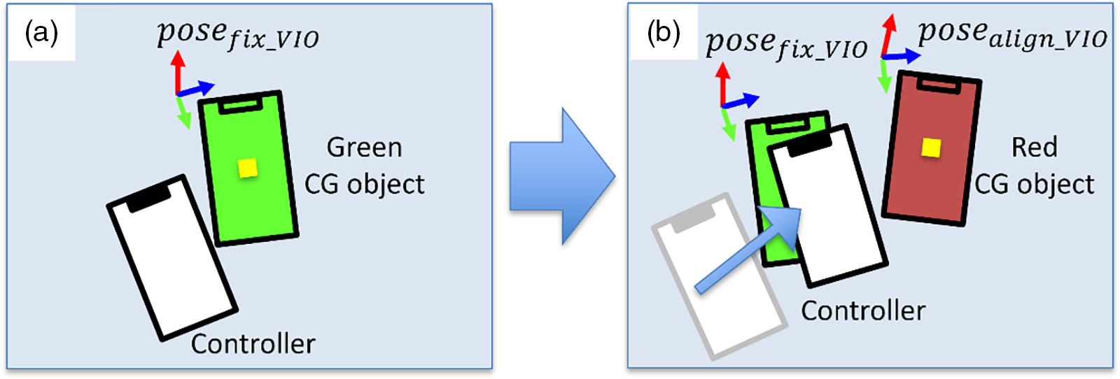
Figure 4: Process example of CM1: (a) Fixing a green computer graphics (CG) object representing the pose estimated by visual-inertial odometry (VIO) (
(2) CM2: Display the controller’s marker within the FoV of the D-device camera in advance, and the amount of change between poses estimated by marker recognition (
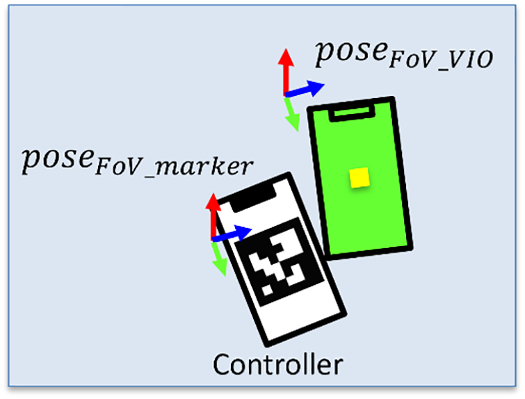
Figure 5: Process example of CM2, CM3: If the controller is within the field of view (FoV) of the D-device, the controller pose is estimated using marker recognition (
(3) CM3: Unlike CM2, if there is a marker on the controller’s screen within the FoV of the D-device camera, the correction data is continuously corrected by marker recognition. If the controller exists outside the FoV of the D device’s camera, calculate the pose of the controller by adding correction data to the pose estimated by VIO.
CM2 and CM3 calculate correction data as follows:
Finally, the corrected poses (position (
An example of the modified pose when performing correction using the above method is shown in Fig. 6.
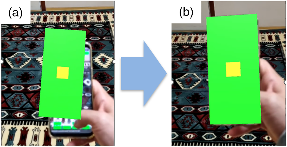
Figure 6: Correction of controller pose estimated by VIO: (a) before and (b) after correction
3.3 Tracking Algorithm Design Strategy
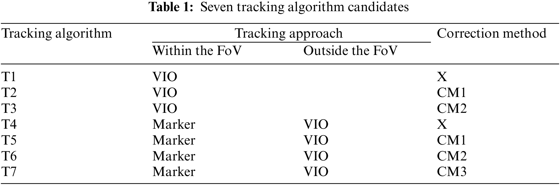
In Sections 3.1 and 3.2, the controller pose estimation and correction methods are explained. This section explains the design of the seven tracking algorithm candidates.
Fig. 7 shows the coordinate systems that can be used depending on the positional relationship between the D-device and the controller. When the controller is within the FoV of the D-device’s camera, the D-device can estimate the controller’s pose using two methods: Marker recognition and VIO (Fig. 7a). Additionally, it can be estimated indirectly through the anchor (Fig. 7b). On the other hand, if the controller is outside the FoV of the D-device’s camera, pose estimation is possible only with the VIO method using the anchor (Fig. 7c). Therefore, the tracking algorithm for estimating the controller’s pose must be designed considering the FoV of the D-device’s camera and the operating area of the controller. The estimated controller’s pose varies depending on the use of correction methods (outlined in Section 3.2). Therefore, when constructing an actual system, it is necessary to consider the following: 1) whether correction work can be performed before using the controller as an input interface, 2) the ease of correction for the user regarding the controller’s pose, and 3) the computing power available on the D-device. Drawing from these considerations, the seven tracking algorithm candidates shown in Table 1 were considered.
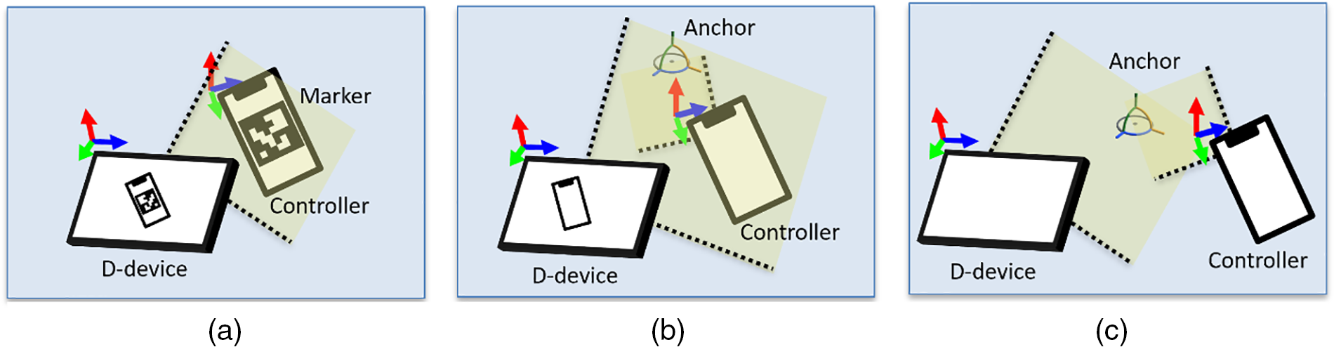
Figure 7: Tracking approaches for positional relationship between D-device and controller: Within the FoV ((a) marker recognition, (b) VIO) and outside the FoV ((c) VIO) of D-device’s camera
To evaluate the characteristics of each of the tracking algorithm candidates (T1~T7) explained in Section 3.3, two experiments were conducted to compare the pose (position and orientation) of the controller estimated by each tracking algorithm. As shown in Fig. 8, Meta Quest2 (HMD and two VR controllers (L-sensor and R-sensor)) was added along with two smartphones (D-device and controller) to obtain the ground truth (GT) of the controller pose. A calibration tool consisting of a checkerboard (ChArUco) and the R-sensor (Fig. 8a) was installed to determine the relationship between the coordinate systems of the D-device and Meta Quest2. Notably, the difference in pose between the checkerboard and R-sensor was pre-measured. Additionally, by measuring the pose of the L-sensor attached to the controller (Fig. 8b), the actual pose of the controller was estimated.
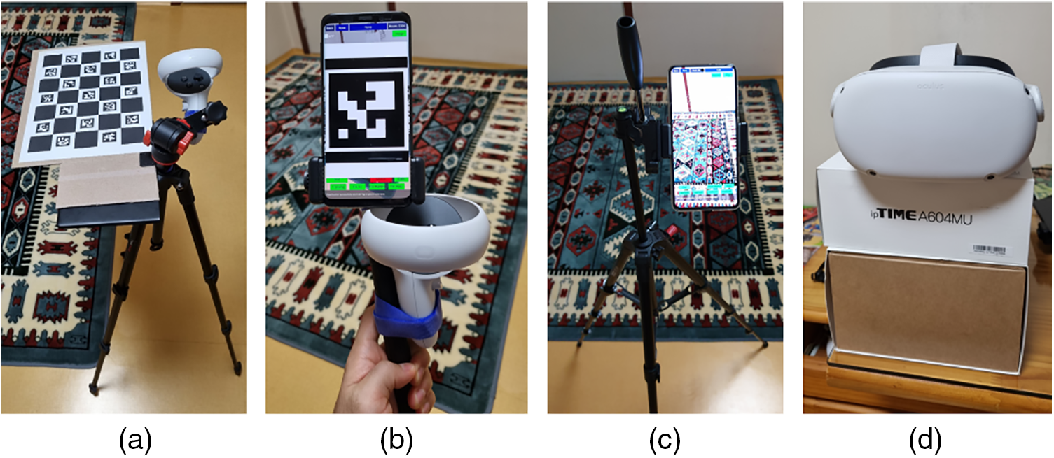
Figure 8: System configuration (a) calibration tool (ChArUco and R-sensor), (b) a controller with L-sensor attached, (c) D-device fixed on a tripod, (d) HMD (camera) for tracking L-sensor and R-sensor
During the experiments, we assumed that the user would experience the AR application while standing, and evaluated the accuracy of the pose using two types of data (discrete and continuous data). In Experiments 1 and 2, marker recognition was successful when the controller’s marker was within the FoV of the D-device camera. In addition, the D-device placed the anchor after slowly and sufficiently scanning the location for anchor placement, and the D-device was fixed on a tripod after placing the anchor (Fig. 8c). The controller moved around the environment containing the anchor.
4.1 Experiment 1: Discrete Data
In Experiment 1, aimed at comparing the controller’s pose estimated by the tracking algorithm with the GT, the task of selecting a CG target (a blue cube with sides of 2 cm) was performed as shown in Fig. 9. The procedure is as follows. First, estimate the pose of the D-device using VIO and place an anchor on the D-device coordinate system. Subsequently, we position 16 CG targets in the D-device coordinate system based on the D-device’s pose. Along the z-axis (depth direction of the D-device camera), eight targets are located at 25 cm, while the remaining eight targets are located at 35 cm (Figs. 9a, 9b). Using a green CG object representing the estimated pose of the controller by the tracking algorithm, a task of pointing each target was performed for 5 s (Fig. 9c).
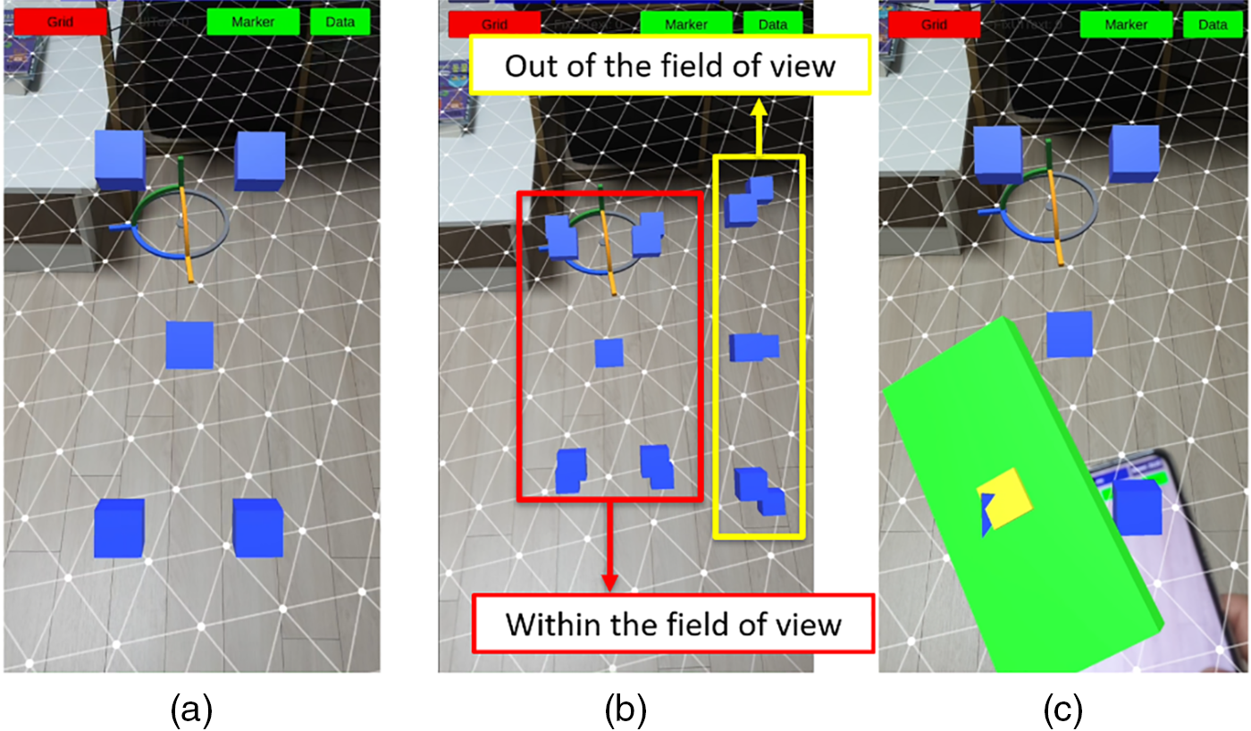
Figure 9: Example of performing the task of Experiment 1: (a) screen of D-device, (b) all targets placed in D-device coordinate system (within and outside the FoV of D-device’s camera), (c) estimated pose of the controller is pointing to the blue CG target
Furthermore, if the distance between the centers of the CG object and the target was within 2 cm, the target was correctly selected. In addition, when pointing to a target located outside the FoV of the D-device camera, the estimated pose of the controller and the pose of the target were numerically displayed on the controller screen, given that the target was not visible on the D-device. This task was repeated twice for each tracking algorithm during the experiment.
The results of Experiment 1 are presented in Tables 2 and 3. For targets exist within the FoV of the D-device’s camera, both position (
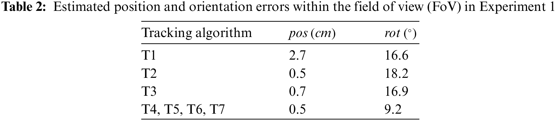
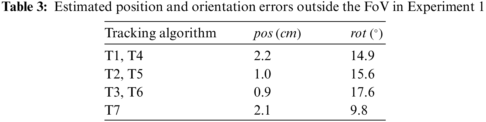
For targets outside the FoV of the D-device’s camera, a comparison was made between the VIO-based tracking algorithm and three tracking algorithms that correct the pose (CM1~CM3) estimated by VIO. The results showed that using the algorithm combining CM1 (T2/T5) or CM2 (T3/T6) significantly reduces the position error compared with the algorithm using only VIO (T1/T4). (between T1/T4 and T2/T5: T = 10.90, p < 0.001, between T1/T4 and T3/T6: T = 12.83, p < 0.001). Additionally, for four conditions (T1/T4 (VIO only), T2/T5 (VIO with CM1), T3/T6 (VIO with CM2), and T7 (VIO with CM3)), significant differences in orientation errors were obtained between the conditions (F = 5.303, p < 0.01), Notably, T7, which combines VIO with CM3 had the smallest error. Because CM3 makes corrections based on the position and orientation estimated by marker recognition immediately before it leaves the camera’s FoV, it inferred that the orientation error was smaller compared to CM1 and CM2.
4.2 Experiment 2: Continuous Data
In Experiment 2, the continuous values of the position and orientation estimated by seven candidate tracking algorithms (T1~T7) with GT were compared to evaluate the movement trajectory of the controller. The task involved moving the controller along a path displayed in CG in the AR space. The path, shown in Fig. 10, took on a triangular and rectangular shape, resulting in four distinct types: One with the entire route within the FoV of the D-device’s camera and another with a portion of the route outside the FoV. All paths entailed variations in translation along the x, y, and z axes of the D-device coordinate system. For this experiment, a dataset was created using ARCore’s Recording and Playback API [29] to evaluate the performance of the tracking algorithm when the controller made the same movement.
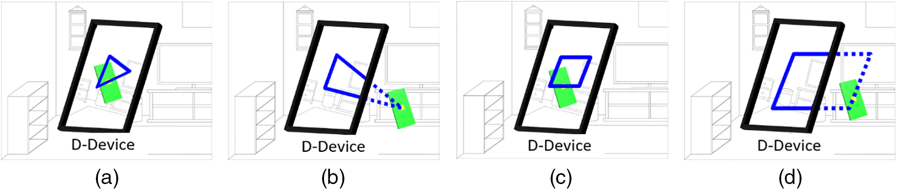
Figure 10: Example of four paths in Experiment 2: (a) TRI1, (b) TRI2, (c) REC1, (d) REC2
Initiate recording while applying VIO on the D-device. Conduct a comprehensive scan of the real environment and generate an environment map with suitable quality for placing the anchor. Similarly, the controller scans the real environment and places the anchor. Subsequently, we perform calibration to integrate the Meta Quest coordinate system and the D-device coordinate system. To estimate the controller’s pose, we calculate the correction data using CM1 and CM2 and obtain the pose of the L-sensor in advance. Following this, repeat the task of moving the controller along each path three times. Upon completion of all tasks, save the acquired data (controller’s pose estimated by T1~T7, RGB images, IMU, and D-device’s pose) at a rate of 20 Hz. At this time, calculations by T1~T7 were each processed within 50 ms, and the pose value was updated every frame.
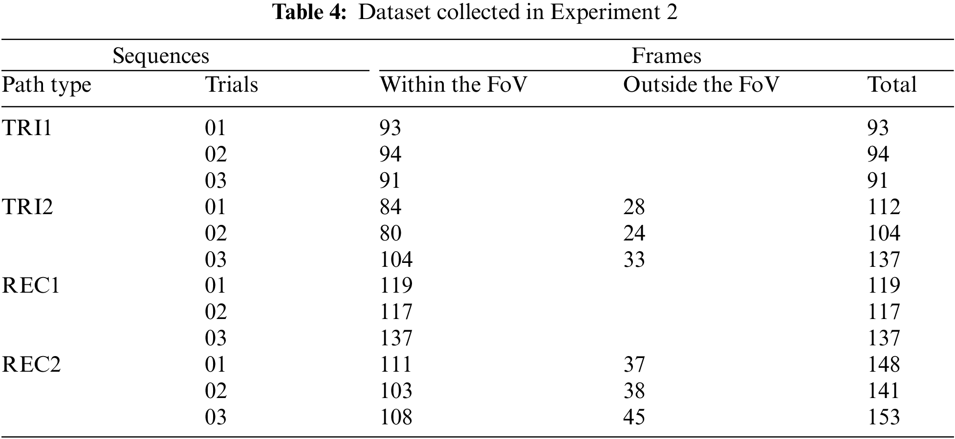
The playback mode loads the data saved in the recording mode and outputs the GT corresponding to the timestamp of the estimated pose. Considering that the estimated controller pose and GT sampling rate are 20 and 60 Hz, respectively, the data correspondence is adjusted by referring to the study [30]. Finally, the GT and the estimated pose are acquired at 20 Hz, generating a total of 12 sequences ((path type: 4) × (number of trials: 3)) as shown in Table 4.
The accuracy was evaluated by comparing the pose estimated by T1~T7 and GT using a quantitative path evaluation tool [31]. This tool [31] employs a path alignment method for VIO, providing absolute path error (ATE) and relative error (RE) as error metrics for path evaluation between GT and the estimated pose. ATE measures the error without aligning two paths, whereas RE measures the error after aligning the paths in advance. The root mean square error (RMSE) values of the ATE’s position, orientation, and RE’s position (
Table 5 shows the results of sequences that moved only within the FoV of the D-device’s camera (TRI1 and REC1). The tracking algorithms using only marker recognition (T4~T7) had significantly smaller
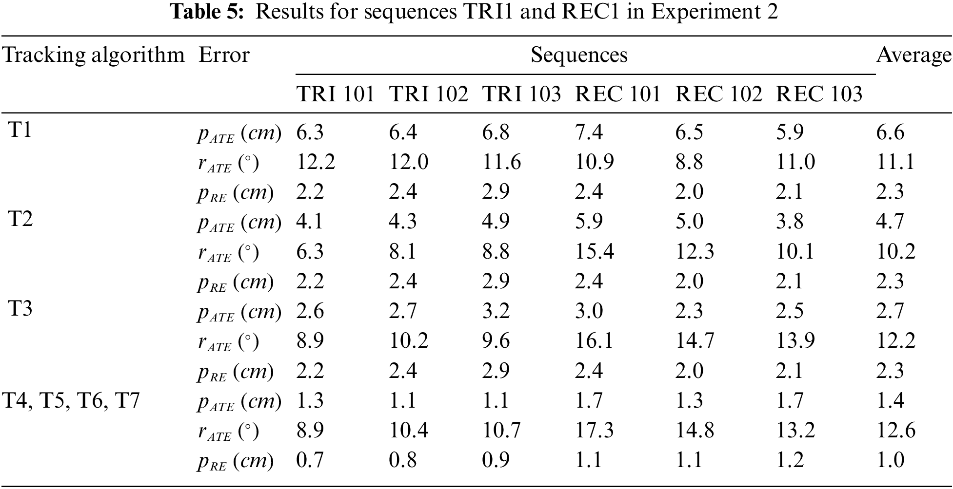
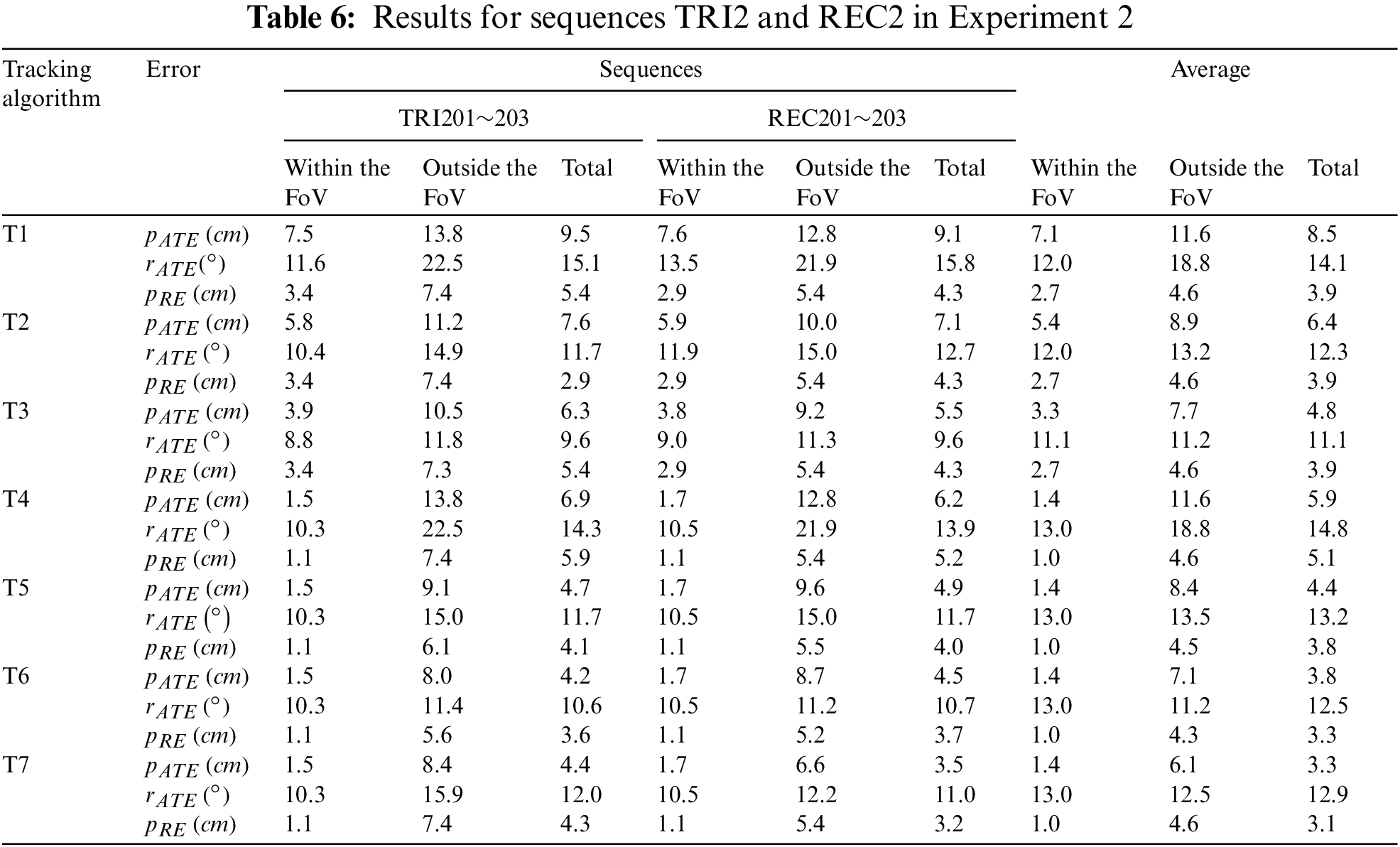
Table 6 shows the results for the sequences TRI2 and REC2. Regarding movement within the FoV of the D-device’s camera, the tracking algorithm based on marker recognition (T4~T7) had the smallest
When using a smartphone pose value as an input interface, the potential issue of delay time may arise. This study investigated a tracking algorithm based on VIO and marker recognition. For VIO, the pose of the controller is estimated by image processing for each frame, and the pose in the anchor coordinate system is sent to the D-device via the Wi-Fi network, resulting in a delay time. For T4~T7, when the controller is within the FoV of the D-device’s camera, marker recognition is performed while simultaneously creating an environment map with VIO, leading to potential delays due to increased processing costs. To solve these problems, it is necessary to introduce higher-performance devices and optimize tracking algorithms. Additionally, if the real environment in which the system will be used is known, a map of the environment can be created in advance to reduce the amount of computation through map-based localization [20].
Fig. 11 shows the trajectories of the estimated poses moving inside and outside the FoV of the D-device’s camera (TRI2, REC2) in Experiment 2. When the tracking approach is different between the inside and outside of the FoV of the D-device’s camera, it was observed that the estimated pose values change significantly at the boundary between the inside and outside the FoV, causing the trajectory to become discontinuous. Additionally, there was a 150 ms time difference between the marker recognition-based and VIO-based pose timestamp estimated by the D-device for each frame. To smooth the movement path of the controller, it is essential to consider applying filtering based on signal processing such as the Kalman filter.
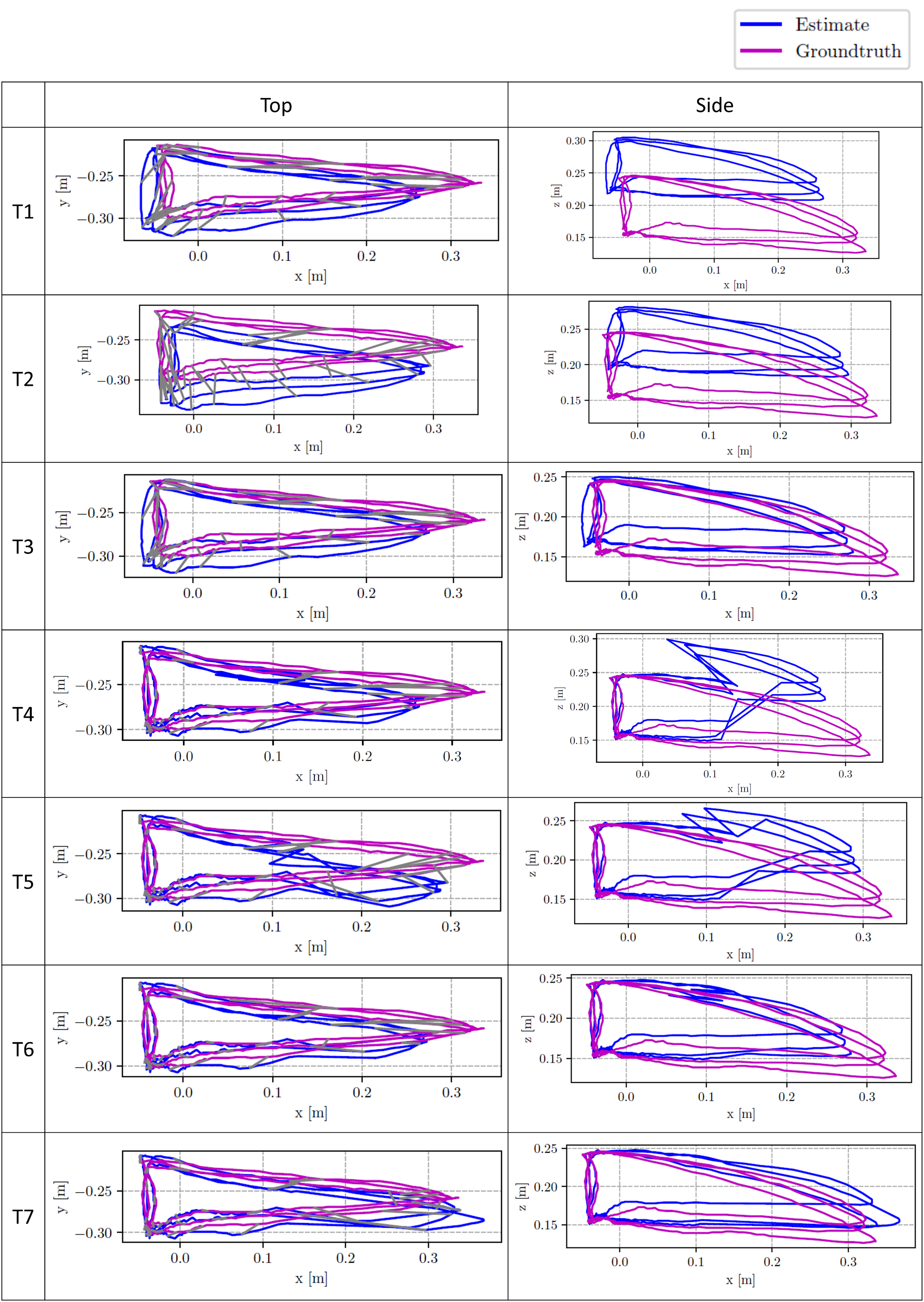
Figure 11: The absolute trajectories of the estimated poses moving inside and outside the FoV of D-device’s camera on the path of TRI2 (With the pose of the D-device as the origin, the x, y, and z axes are in the left-right, up-down, and forward-backward directions, respectively. Top and side view are the paths seen from the z- and y-axis, respectively)
In the case of T4~T7, there is a risk that marker recognition may fail due to rapid movement within the FoV of the D-device’s camera. Since the controller has an IMU sensor, a more sophisticated pose estimation can be conceived by considering the IMU data along with visual markers. In the case of VIO, effects due to rapid movement may also occur, and limitations need to be investigated.
Compared to CM2 and CM3, which perform calibration by automatically moving the controller, CM1 requires more time to perform accurate calibration. In this experiment, it took approximately 30 s.
5.2 Strategy for Using Pose Values as an Input Interface
Section 4 compares the pose estimated by the seven tracking algorithm candidates with GT, and finds that it is crucial to select an appropriate tracking algorithm depending on the interaction range of the controller and the actual input values used as an input interface. In this section, a strategy based on the data type for using the smartphone’s pose as an input interface is explained. Please note that tracking algorithms that do not use correction methods (T1 and T4) and tracking algorithms that use manual correction methods (T2 and T5) are excluded from recommendation.
Discrete data can be used for input manipulation, such as pointing and selection. When a virtual object is sufficient to reach, it can be directly manipulated using the smartphone as a cursor displayed in 3D space. Additionally, when the virtual object is out of reach, ray casting can be used. In this case, tracking algorithms such as T6 and T7, which have small errors in pose within the FoV of the D-device’s camera, are effective. When a smartphone interacts within and outside the FoV, tracking algorithms such as T6, which has small position errors, are effective.
When using the continuous movement of a smartphone as an input, tasks such as 3D drawing and accurate placement of virtual objects can be performed from the absolute value of continuous data. In addition, the user’s relative movement can also be used as an input manipulation, such as gesture recognition. In this case, tracking algorithms such as T6 and T7, which have small
5.2.3 Manipulation Near the Boundary Inside and Outside the FoV
As mentioned in Section 5.1, tracking algorithms that use different tracking approaches for inside and outside the FoV may cause discontinuity in the estimated pose at the boundary between inside and outside the FoV. According to Fig. 11, compared to T6, which draws a discontinuous path at the boundary inside and outside the FoV, T7 draws a relatively smooth path. This shows that the amount of pose change is small when CM3 changes from inside the FoV to outside the FoV. Meanwhile, if much work is required near the boundary between inside and outside the FoV, T3, which has the same tracking approach for inside and outside the FoV, may be appropriate depending on the application.
This study investigated the use of a smartphone’s pose as an input interface for 3D interaction. Seven inside-out tracking algorithms were presented using only the built-in sensors of the D-device with controller and the accuracy of the estimated pose was evaluated in two experiments. Compared with a tracking algorithm using only VIO, the pose accuracy was improved by combining correction methods. In particular, regardless of whether the controller moves inside or outside the FoV of the D-device camera, marker recognition was used within the FoV, and a method combining VIO, and correction methods was used outside the FoV to improve pose accuracy. In conclusion, from a general perspective, T6 and T7 are recommended for use as an input interface, and T3 is recommended when a lot of work require around the border between inside and outside the FoV of the D-device’s camera. Future work will consider optimizing the tracking algorithm to shorten the pose estimation time. In addition, experiments on users using the tracking algorithms to verify its usefulness as an input interface for 3D interaction will be conducted.
Acknowledgement: We would like to thank our laboratory members for useful discussions.
Funding Statement: The authors received no specific funding for this study.
Author Contributions: The authors confirm contribution to the paper as follows: Study conception and design: Takefumi Ogawa, Chanho Park; data collection: Chanho Park; analysis and interpretation of results: Chanho Park; draft manuscript preparation: Chanho Park. All authors reviewed the results and approved the final version of the manuscript.
Availability of Data and Materials: Data available on request from the authors.
Conflicts of Interest: The authors declare that they have no conflicts of interest to report regarding the present study.
References
1. HTC, “HTC VIVE,” 2024. Accessed: Mar. 28, 2024. [Online]. Available: https://www.vive.com [Google Scholar]
2. Microsoft, “MS HoloLens 2,” 2024. Accessed: Mar. 28, 2024. [Online]. Available: https://www.microsoft.com/en-us/hololens/hardware [Google Scholar]
3. Meta, “Meta Quest 2,” 2024. Accessed: Mar. 28, 2024. [Online]. Available: https://www.meta.com/us/en/quest/products/quest-2/ [Google Scholar]
4. Google, “ARCore,” 2024. Accessed: Mar. 28, 2024. [Online]. Available: https://developers.google.com/ar [Google Scholar]
5. Apple, “ARkit,” 2024. Accessed: Mar. 28, 2024. [Online]. Available: https://developer.apple.com/augmented-reality/arkit [Google Scholar]
6. Google, “Google Cardboard,” 2024. Accessed: Mar. 28, 2024. [Online]. Available: https://arvr.google.com/cardboard [Google Scholar]
7. T. Babic, H. Reiterer, and M. Haller, “Pocket6: A 6DoF controller based on a simple smartphone application,” in Proc. Symp. Spatial User Interact., Berlin, Germany, ACM, Oct. 2018, pp. 2–10. doi: 10.1145/3267782.3267785. [Google Scholar] [CrossRef]
8. K. Hattori and T. Hirai, “Insideout tracking controller for VR/AR HMD using image recognition with smartphones,” in ACM SIGGRAPH 2020 Posters, USA, ACM, Aug. 2020. doi: 10.1145/3388770.3407430. [Google Scholar] [CrossRef]
9. A. E. Unlu and R. Xiao, “Pair: Phone as an augmented immersive reality controller,” in Proc. 27th ACM Symp. Virtual Reality Softw. Technol., Osaka, Japan, Dec. 2021. doi: 10.1145/3489849.3489878. [Google Scholar] [CrossRef]
10. OptiTrack, “Motion Capture Cameras,” 2024. Accessed: Mar. 28, 2024. [Online]. Available: https://optitrack.com [Google Scholar]
11. J. D. Hincapi´e-Ramos, X. Guo, P. Moghadasian, and P. Irani, “Consumed endurance: A metric to quantify arm fatigue of mid-air interactions,” in Proc. SIGCHI Conf. Human Factors Comput. Syst., Toronto, Ontario, Canada, Apr. 2014, pp. 1063–1072. doi: 10.1145/2556288.2557130. [Google Scholar] [CrossRef]
12. A. Henrysson, M. Billinghurst, and M. Ollila, “Virtual object manipulation using a mobile phone,” in Proc. 2005 Int. Conf. Augm. Tele-Exist., Christchurch, New Zealand, Dec. 2005, pp. 164–171. doi: 10.1145/1152399.1152430. [Google Scholar] [CrossRef]
13. R. Vanukuru, A. Murugan, and J. Pillai, “Dual phone AR: Exploring the use of phones as controllers for mobile augmented reality,” in 26th ACM Symp. Virtual Real. Soft. Technol., Canada, ACM, Nov. 2020. doi: 10.1145/3385956.3422113. [Google Scholar] [CrossRef]
14. P. Mohr, M. Tatzgern, T. Langlotz, A. Lang, D. Schmalstieg, and D. Kalkofen, “TrackCap: Enabling smartphones for 3D interaction on mobile head-mounted displays,” in Proc. 2019 CHI Conf. Human Factors Comput. Syst., Glasgow, Scotland, UK, May 2019, pp. 1–11. doi: 10.1145/3290605.3300815. [Google Scholar] [CrossRef]
15. A. Marzo, B. Bossavit, and M. Hachet, “Combining multi-touch input and device movement for 3d manipulations in mobile augmented reality environments,” in Proc 2nd ACM Symp. Spatial User Interact., Honolulu, Hawaii, USA, Oct. 2014, pp. 13–16. doi: 10.1145/2659766.2659775. [Google Scholar] [CrossRef]
16. Ultraleap, “Leap motion,” 2024. Accessed: Mar. 28, 2024. [Online]. Available: https://www.ultraleap.com/product/leap-motion-controller [Google Scholar]
17. C. Park, H. Cho, S. Park, Y. S. Yoon, and S. U. Jung, “HandPoseMenu: Hand posture-based virtual menus for changing interaction mode in 3D space,” in Proc. 2019 ACM Int. Conf. Interact. Surfaces Spaces, Daejeon, Korea, Nov. 2019, pp. 361–366. doi: 10.1145/3343055.3360752. [Google Scholar] [CrossRef]
18. H. Debarba, L. Nedel, and A. Maciel, “LOP-cursor: Fast and precise interaction with tiled displays using one hand and levels of precision,” in 2012 IEEE Symp. 3D User Inter. (3DUI), Costa Mesa, CA, USA, IEEE, Mar. 2012, pp. 125–132. doi: 10.1109/3DUI.2012.6184196. [Google Scholar] [CrossRef]
19. J. G. Grandi, H. G. Debarba, L. Nedel, and A. Maciel, “Design and evaluation of a handheld-based 3D user interface for collaborative object manipulation,” in Proc. 2017 CHI Conf. Human Fact. Comput. Syst., Denver, Colorado, USA, May 2017, pp. 5881–5891. doi: 10.1145/3025453.3025935. [Google Scholar] [CrossRef]
20. C. Campos, R. Elvira, J. J. G. Rodríguez, J. M. M. Montiel, and J. D. Tardos, “ORB-SLAM3: An accurate open-source library for visual, visual-inertial, and multimap SLAM,” IEEE Trans. Robot., vol. 37, no. 6, pp. 1874–1890, Dec. 2021. doi: 10.1109/TRO.2021.3075644. [Google Scholar] [CrossRef]
21. C. Park, H. Cho, S. Park, S. Jung, and S. Lee, “Strategy for creating AR applications in static and dynamic environments using SLAM- and marker detector-based tracking,” Comput. Model. Eng. Sci., vol. 131, no. 1, pp. 529–549, Jan. 2022. doi: 10.32604/cmes.2022.019214. [Google Scholar] [CrossRef]
22. S. Park, H. Cho, C. Park, Y. S. Yoon, and S. U. Jung, “AR Room: Real-time framework of camera location and interaction for augmented reality services,” in 2020 IEEE Conf. Virtual Reality 3D User Inter. Abs. Workshops (VRW), Atlanta, GA, USA, Mar. 2020, pp. 736–737. doi: 10.1109/VRW50115.2020.00219. [Google Scholar] [CrossRef]
23. X. Jiang, L. Zhu, J. Liu, and A. Song, “A SLAM-based 6DoF controller with smooth auto-calibration for virtual reality,” Visual Comput., vol. 39, no. 9, pp. 3873–3886, Jun. 2023. doi: 10.1007/s00371-022-02530-1. [Google Scholar] [CrossRef]
24. M. Kari and C. Holz, “HandyCast: Phone-based bimanual input for virtual reality in mobile and space-constrained settings via pose-and-touch transfer,” in Proc. 2023 CHI Conf. Human Fact. Comput. Syst. (CHI ’23), Hamburg, Germany, ACM, Apr. 2023, pp. 1–15. doi: 10.1145/3544548.3580677. [Google Scholar] [CrossRef]
25. Unity 3D, “UNET 2019.4,” 2019. Accessed: Mar. 28, 2024. [Online]. Available: https://docs.unity3d.com/2019.4/Documentation/Manual/UNet.html [Google Scholar]
26. D. Galvez-López and J. D. Tardos, “Bags of binary words for fast place recognition in image sequences,” IEEE Trans. Robot., vol. 28, no. 5, pp. 1188–1197, Oct. 2012. doi: 10.1109/TRO.2012.2197158. [Google Scholar] [CrossRef]
27. Google, “Arcore cloud anchor,” 2024 Accessed: Mar. 28, 2024. [Online]. Available: https://developers.google.com/ar/develop/cloud-anchors [Google Scholar]
28. S. Garrido-Jurado, R. Muñoz-Salinas, F. J. Madrid-Cuevas, and R. Medina-Carnicer, “Generation of fiducial marker dictionaries using mixed integer linear programming,” Pattern Recognit., vol. 51, no. 3, pp. 481–491, Mar. 2016. doi: 10.1016/j.patcog.2015.09.023. [Google Scholar] [CrossRef]
29. Google, “Arcore recording and playback introduction,” 2024. Accessed: Mar. 28, 2024. [Online]. Available: https://developers.google.com/ar/develop/recording-and-playback [Google Scholar]
30. J. Sturm, N. Engelhard, F. Endres, W. Burgard, and D. Cremers, “A benchmark for the evaluation of RGB-D SLAM systems,” in IEEE/RSJ Int. Conf. Intell. Robots Syst., Vilamoura-Algarve, Portugal, Oct. 2012, pp. 573–580. doi: 10.1109/IROS.2012.6385773. [Google Scholar] [CrossRef]
31. Z. Zhang and D. Scaramuzza, “A tutorial on quantitative trajectory evaluation for visual(-inertial) odometry,” in 2018 IEEE/RSJ Int. Conf. Intell. Robots Syst., Madrid, Spain, Oct. 2018, pp. 7244–7251. doi: 10.1109/IROS.2018.8593941. [Google Scholar] [CrossRef]
Cite This Article
 Copyright © 2024 The Author(s). Published by Tech Science Press.
This work is licensed under a Creative Commons Attribution 4.0 International License , which permits unrestricted use, distribution, and reproduction in any medium, provided the original work is properly cited.
 Downloads
 Citation Tools