
 Submit a Paper
 Propose a Special lssue
 Open Access
ARTICLE

A Bidimensional Finite Element Study of Crack Propagation in Austempered Ductile Iron
Department of Mechanical Engineering, Federal University of Technology–Paraná, Curitiba, 81280-340, Brazil
* Corresponding Author: Marco Antonio Luersen. Email:
Computers, Materials & Continua 2023, 77(2), 1411-1424. https://doi.org/10.32604/cmc.2023.043811
Received 12 July 2023; Accepted 19 October 2023; Issue published 29 November 2023
 View Full Text
 Download PDF
Abstract
Austempered ductile iron (ADI) is composed of an ausferritic matrix with graphite nodules and has a wide range of applications because of its high mechanical strength, fatigue resistance, and wear resistance compared to other cast irons. The amount and size of the nodules can be controlled by the chemical composition and austenitizing temperature. As the nodules have lower stiffness than the matrix and can act as stress concentrators, they influence crack propagation. However, the crack propagation mechanism in ADI is not yet fully understood. In this study, we describe a numerical investigation of crack propagation in ADIs subjected to cyclic loading. The numerical model used to calculate the stress intensity factors in the material under the given conditions is built with the aid of Abaqus commercial finite element code. The crack propagation routine, which is based on the Paris law, is implemented in Python. The results of the simulation show that the presence of a nodule generates a shear load on the crack tip. Consequently, even under uniaxial tensile loading, the presence of the nodule yields a non-zero stress intensity factor in mode II, resulting in a deviation in the crack propagation path. This is the primary factor responsible for changing the crack propagation direction towards the nodule. Modifying the parameters, for example, increasing the nodule size or decreasing the distance between the nodule and crack tip, can intensify this effect. In simulations comparing two different ADIs with the same graphite fraction area, the crack in the material with more nodules reaches another nodule in a shorter propagation time (or shorter number of cycles). This suggests that the high fatigue resistance observed in ADIs may be correlated with the number of nodules intercepted by a crack and the additional energy required to nucleate new cracks. In summary, these findings contribute to a better understanding of crack propagation in ADIs, provide insights into the relationship between the presence of nodules and the fatigue resistance of these materials, and support studies that associate the increased fatigue resistance with a higher number of graphite nodules. These results can also help justify the enhanced fatigue resistance of ADIs when compared to other cast irons.Keywords
The first ductile cast irons (DCIs) were developed in the 1940s after magnesium or cerium were added to conventional cast iron [1]. This was followed in the 1970s by the development of austempered ductile iron (ADI), which consists of an ausferrite matrix with graphite nodules. ADI is commonly used in applications such as gears, cams and followers because of its excellent wear resistance [2,3], and significant advances in production techniques have enabled high-strength ADIs to be manufactured [4].
ADI has a lower relative material cost compared with cast and forged steels [5]. Furthermore, ADI exhibits superior mechanical strength, ductility, toughness, fatigue resistance and wear resistance compared to other cast irons [2]. The mechanical properties of ADI are also influenced by the heat-treatment temperature, which affects the microstructure of the material [6–9].
Another factor impacting the properties of ADI is the size and quantity of graphite nodules. Given their lower mechanical strength and stiffness compared to the matrix, ADI graphite nodules function as discontinuities and, consequently, act as stress concentrators [10,11]. Consequently, they are prone to crack initiation, affecting ADI’s fatigue strength [12]. Furthermore, the geometric characteristics of these nodules, including their size and distribution, alter the stress distribution within the matrix, thereby modifying the conditions conducive to crack propagation. Since the mechanical properties of ADI are influenced by the size and distribution of graphite nodules, comprehending how these factors impact the initiation and propagation of fatigue cracks is crucial for enhancing the applicability of ADI. Rebasa et al. [13], studying various ADIs and ferritic ductile irons (FDIs), showed that the amount of graphite nodules can range from 100 to 1500 nodules/mm². They concluded that samples with a higher nodule count exhibit increased rolling contact fatigue (RCF) resistance, indicating that the number of nodules plays a crucial role in extending the lifespan of these materials. Dommarco et al. [14] demonstrated that nodule size also affects RCF life and found that this increased significantly as nodule size decreased. Gans et al. [15] reported that the size and number of nodules in ADI influence the nucleation and propagation stages of cracks and that more nodules lead to enhanced wear resistance.
Fatigue crack propagation in ADI was investigated by Greno et al. [16], who found that cracks tend to intercept graphite nodules. The propagation mechanism involves the growth of small cracks originating at the nodules and progressing towards the main crack. According to Stokes et al. [17], the initiation of dominant fatigue cracks occurs exclusively in pores (superficial and sub-superficial), and in the absence of these defects, crack initiation occurs within graphite nodules. Growth of the main crack can be altered through coalescence with secondary cracks, resulting in a more tortuous crack path and potential shielding effects. Chapetti [18] conducted a study on an ADI grade 2 (ASTM 897 M-90) and observed that its fatigue limit is influenced by the “micronotch” effect caused by graphite nodules and the relative orientations of the microstructure at the ausferrite packet boundaries.
Several authors [15,19–24] have conducted finite element analysis (FEA)-assisted studies to examine ADIs and DCIs at the microscopic level. FEA simulations aim to determine the lifetime of a component by understanding the failure mechanisms of the material, including factors influencing fatigue, such as stress intensity factors. In the case of ADI, it is crucial to understand the influence of graphite nodules on these factors and, consequently, crack propagation.
In this work, we investigate the influence of nodules on crack propagation in ADI subjected to cyclic loads using a two-dimensional finite element model. The presence of nodules induces a mixed state of stress combining normal and shear stresses. To assess crack behavior under cyclic loading, including growth rate, crack path and estimation of the fatigue lifetime of the component, we implement an iterative crack growth method based on the Paris law. This study contributes by offering insights to enhance our understanding of crack propagation in ADI, with a particular focus on highlighting the presence and influence of the stress intensity factor in mode II. This aspect has received limited investigation until now. While our two-dimensional approach may initially appear simplified and may not provide quantitatively accurate values, it does offer a clear qualitative depiction of the underlying phenomena.
2 Crack Propagation: Approach and Modelling Details
To simulate crack propagation in ADI and analyze the stress intensity factors as the crack grows, a Python-based computational routine was developed in the Abaqus environment. The routine iteratively calculates crack propagation considering various parameters such as geometry, material properties, initial crack conditions (size, position and angle), boundary conditions and the size and location of nodules.
The routine reads the input data and communicates it to the Abaqus finite element commercial program, which processes the model. This involves applying the specified loads, obtaining stresses, strains and displacements and calculating the stress intensity factors. At each iteration, the crack propagates, and its size is updated accordingly. The simulation continues until a stop criterion is met, such as reaching the maximum number of cycles or the crack encountering a nodule.
Some simplifications are made in the mechanical model. Firstly, the FEA model is restricted to two dimensions (2D) and represents the graphite nodules as circumferences that approximate cylinders in 3D. Additionally, the model assumes linear elastic fracture mechanics theory and neglects the effects of plasticity. Therefore, the stress analysis at the crack tip is only used to calculate the stress intensity factors. Lastly, the interface between graphite and austenite in the ADI is considered fully bonded, and no allowance is made for a gradual variation of properties between the two materials. Despite these simplifying assumptions, the qualitative results obtained are in line with those of experimental studies and offer important insights into crack propagation in ADIs, as can be seen in Sections 3 and 4 of this paper.
The bidimensional finite element mesh is constructed in Abaqus with six-node triangular quarter-point elements around the crack tip and eight-node quadratic elements in the other regions. Quarter-point elements are specifically used to model singularities, such as crack tips, and provide a more accurate calculation of the stress intensity factors compared with commonly used elements [25,26].
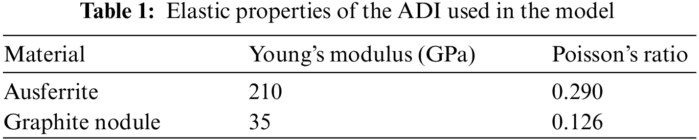
The elastic properties of the ADI used in the model were obtained by Yan et al. [27] and are shown in Table 1.
The number of cycles associated with crack growth size is calculated with the Paris law and an effective (or equivalent) stress intensity factor (Keff) proposed by Tanaka [28]. Thus, the influence of crack opening mode II is considered when calculating crack growth. At the end of each iteration, the routine calculates the crack propagation value, Δai, based on the value of the equivalent stress intensity factor range, ΔKeff. Therefore, the number of cycles for each iteration, ΔNi, is given by
where
The values used for C and m are those found by Greno et al. [16] for the ADI matrix (2.891 × 10⁻¹¹ and 2.74, respectively).
The total number of cycles, N, until the end of the crack propagation simulation is given by the sum of the number of cycles in each iteration, ΔNi, for all n iterations:
To calculate the direction of crack propagation, θ, in each iteration, an Abaqus subroutine is used. This routine is based on the criterion of maximum tangential stress developed by Erdogan et al. [29], where
if KII > 0 then θ < 0, otherwise θ > 0.
The routine ends when one of the stopping criteria is reached. This may be a maximum number of iterations, an admissible value of Keff, or if the crack intercepts a nodule.
3.1 Case 1—Study of the Influence of an Isolated Graphite Nodule on Crack Propagation
In this case study we adopted a geometry based on that used by Silva et al. [30] to investigate the influence of isolated graphite nodules on crack propagation. The dimensional parameters, force range and constraints are depicted in Fig. 1.
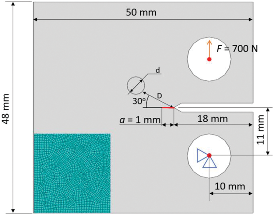
Figure 1: Geometry, load, boundary conditions and mesh density for Case 1
Three subcases are studied, each with a different nodule diameter (d): 4, 6 and 8 mm. The nodule is positioned 8 mm away from the origin of the crack (distance D). The angle between the center of the nodule and the crack tip relative to the horizontal axis is set to 30°. The initial crack size (a0) is 1 mm, as shown in Fig. 1. To apply force and constraints, two representative rigid bodies are created, with the force applied to the center of the upper rigid body, while the other one is subjected to displacement constraint conditions. A global element size of 0.4 mm is used to generate the mesh. The mesh density used can be seen in the lower left corner of Fig. 1.
The results for crack propagation are shown in Fig. 2. In each subcase, the crack deviates from the horizontal direction towards the nodule. Specifically, in subcases (b) and (c), the crack reaches the nodule.
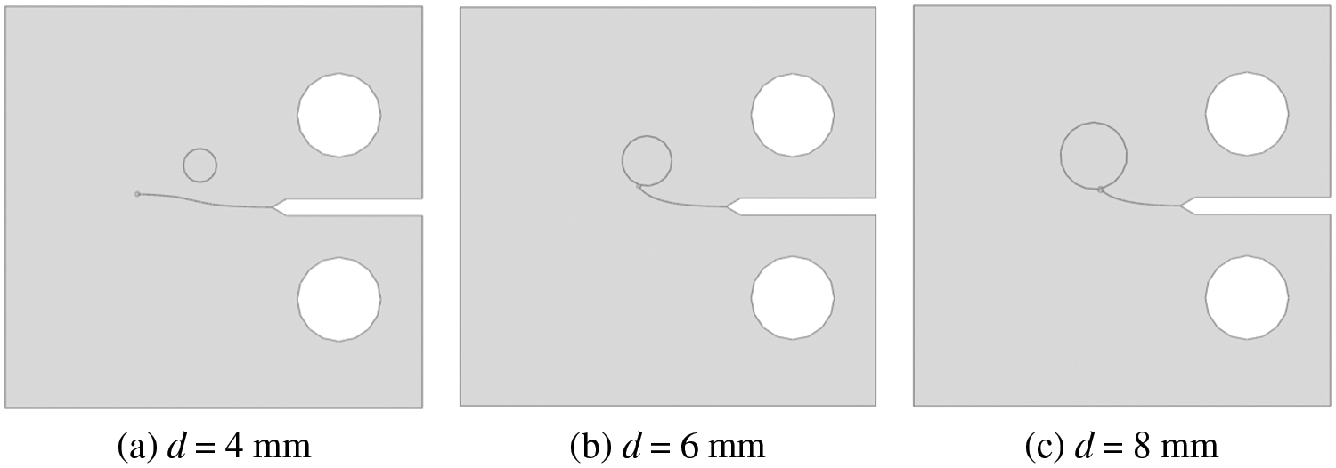
Figure 2: Crack propagation for different nodule diameters (Case 1)
The stress intensity factor range variation as the crack propagates is also examined. Fig. 3 shows the values of the stress intensity factor for mode I (tensile-ΔKI) and mode II (shearing-ΔKII) as a function of the horizontal coordinate (x) of the crack path. There is a significant difference in magnitude between these two factors, and ΔKII is at least 10 times lower than ΔKI. Consequently, the equivalent stress intensity factor range (Eq. (2)) in the subcases described in this section is approximately equal to the stress intensity factor range for mode I. However, the behavior of the stress intensity factor for mode II remains important as it influences the direction of crack propagation (see Eq. (4)). A positive value for this factor causes the crack to propagate towards the nodule. In the subcase in Fig. 2(a), where the nodule diameter is 4 mm, a negative value for KII appeared after several iterations, resulting in deviation of the crack away from the nodule.
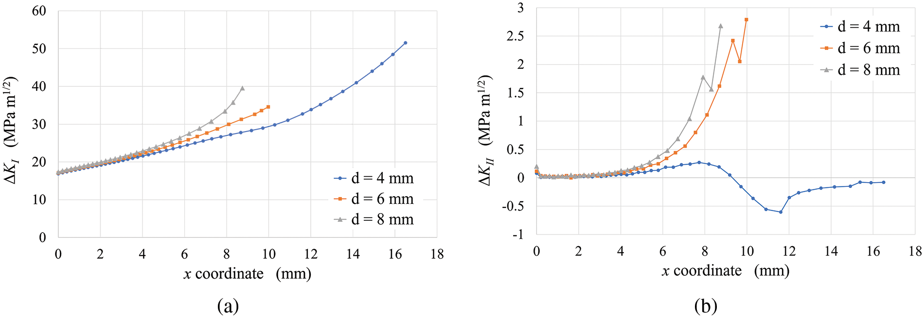
Figure 3: Variation of the stress intensity factor range in mode I (a) and mode II (b) for different nodule sizes (Case 1)
The relationship between crack length (a) and number of cycles (N) is also examined. The results of this analysis are shown in Fig. 4. It is clear that, for the same number of cycles, crack propagation is more significant with larger nodule diameters. Specifically, the presence of larger nodules leads to faster crack propagation and, consequently, a shorter fatigue life.

Figure 4: a-N curves for different nodule sizes (Case 1)
In another subcase, of which, however, for the sake of brevity, only the conclusion is reported here, the variation in the distance D between the nodule and crack tip was explored. As the crack tip approached the nodule, the stress intensity factor was found to increase, causing the crack to deviate and grow faster towards the nodule. This effect is similar to the influence of increasing nodule size.
3.2 Case 2—Study of the Influence of Multiple Graphite Nodules on Crack Propagation
Once again, using the geometry proposed by Silva et al. [30] with adaptations, the influence of two nodules is analyzed, as depicted in Fig. 5. Two circles with graphite properties, each having a diameter of 4 mm, are introduced to the geometry at an initial distance of 8 mm from the crack tip. The position of the lower nodule is adjusted horizontally in 2 mm increments to investigate its effect on the stress intensity factors and crack growth as a function of the number of cycles and direction of propagation.

Figure 5: Geometry of Case 2 with two graphite nodules
The results of crack propagation for all the subcases studied are presented in Fig. 6. As expected, in the initial subcase, where the geometry is symmetrical (Subcase 2.1), the crack propagates without deviation. However, in the other subcases, the crack deviates towards the closer nodule and then changes direction towards the other nodule.
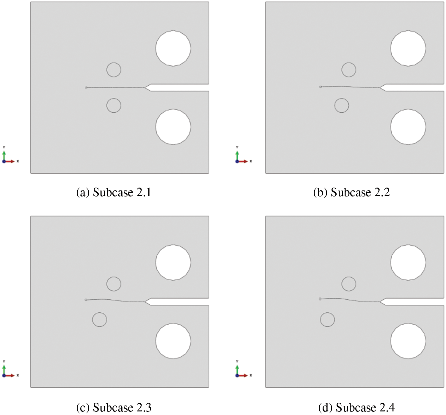
Figure 6: Crack paths for subcases with two graphite nodules (Case 2)
The equivalent stress intensity factor range along the horizontal coordinate of the crack path is illustrated in Fig. 7; no significant differences can be observed between the four subcases. Consistent with the findings of previous studies, the stress intensity factor in mode II, shown in Fig. 8, plays a crucial role in determining the direction of crack propagation. This is even more apparent when the nodules are positioned symmetrically (Subcase 2.1), where ΔKII remains close to zero throughout all iterations.

Figure 7: Variation of the equivalent stress intensity factor range for the subcases studied (Case 2)
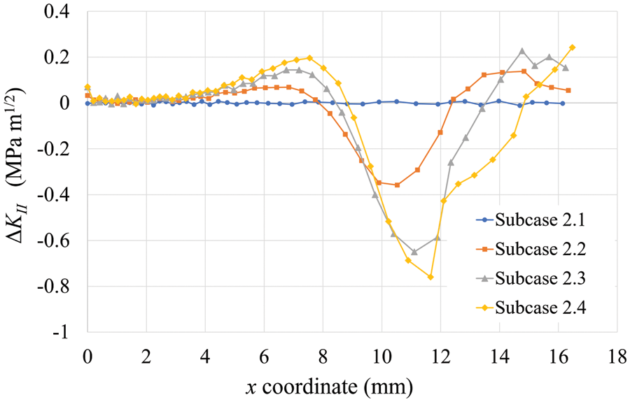
Figure 8: Variation of the stress intensity factor range in mode II along the horizontal coordinate of the crack path for the subcases studied (Case 2)
Finally, the a-N curve (Fig. 9) confirms the earlier observation regarding the equivalent stress intensity factor curve, as there are once again no substantial differences in crack propagation speed between the four subcases. However, the presence of an additional nodule significantly influences the direction of crack propagation. Subcase 2.4, where the lower nodule is positioned at a greater distance from the crack, clearly illustrates significant convergence towards the other nodule.

Figure 9: Crack size as a function of the number of cycles (curve a-N) for Case 2
3.3 Case 3—Study of Crack Propagation in an ADI Structure
In this case study, a representative area measuring 1 mm × 1 mm in ADI is subjected to cyclic tensile loading in the vertical direction ranging from 0 to 60 MPa. To mitigate potential edge effects caused by the applied load, a central area measuring 0.8 mm × 0.8 mm is defined within which the graphite nodules are positioned. The characteristics of the materials, as described by Gans et al. [15], are used to add graphite nodules within this designated area, as shown in Table 2. The first nodule is positioned at the center of the geometry, while the remaining nodules are randomly distributed throughout the defined area. A crack 0.01 mm long is introduced perpendicular to the applied load and emanating from the central nodule. This crack-initiation approach is based on the findings of Stokes et al. [17] for ADI in the absence of other defects. Fig. 10 illustrates this case.
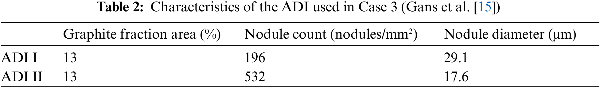

Figure 10: Geometry and boundary conditions (left) and initial mesh used for a representative ADI area (Case 3)
The overall element size for these simulations is set at 0.025 mm. However, mesh refinement is applied in the region of the nodules, as depicted in the detail shown in Fig. 10. For each type of ADI, five subcases are simulated with randomly positioned nodules. Fig. 11 provides an example for each ADI and highlights the difference in the number of nodules between the two materials due to differences in nodule diameter.

Figure 11: Nodule distribution and crack propagation samples for subcases with nodules randomly positioned in the ADIs (Case 3)
The equivalent stress intensity factor range is determined as the crack propagates, as shown in Fig. 12. The behavior in this case does not follow a pattern. One notable observation is the reduction in the value of ΔKeff at certain times despite the increase in crack size. This could potentially be attributed to the increasing distance between crack tip and nodule.

Figure 12: Variation of the equivalent stress intensity factor range for the five subcases studied for ADI I (a) and ADI II (b) (Case 3)
When the equivalent stress intensity factor ranges for ADI I and ADI II are compared, a notable difference in the initial values of this factor becomes apparent. At the onset of the crack, the value for ADI I is approximately 12.2 MPa m1/2, whereas for ADI II, it is slightly lower at around 10 MPa m1/2.
Examination of the a-N curve in Fig. 13 reveals a significant disparity between ADI I and ADI II. There is a considerable acceleration in crack growth in the material with larger nodules (ADI I) because the crack in this material is longer for a given number of cycles.
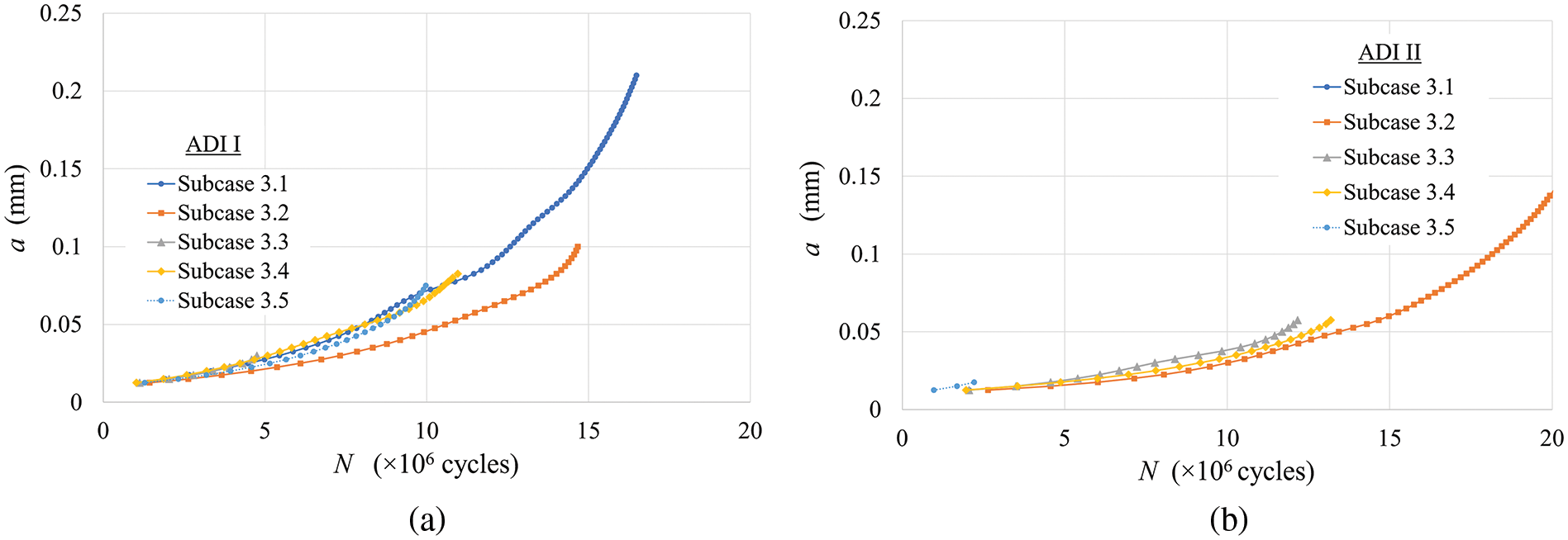
Figure 13: Comparison of a-N curves for each of the five subcases for ADI I (a) and ADI II (b) (Case 3)
Furthermore, the results demonstrate that cracks in the material with more nodules (ADI II) tend to propagate shorter distances before intercepting a new nodule along their path, as illustrated in Fig. 13. This behavior can be attributed to the significantly higher number of nodules in this material compared with ADI II. On average, the crack grew by 0.071 mm in ADI I, whereas in ADI II the corresponding figure was approximately half this value, or 0.036 mm.
It is worth recalling that the cracks tend to propagate towards the nodules and that the magnitude of this attraction depends on nodule size and the distance to the nodule. This characteristic improves the fatigue resistance of ADIs compared with that of other cast irons.
A numerical and computational approach was implemented in conjunction with commercial finite element code to study crack propagation in ADI.
In the cases studied to demonstrate the influence of graphite nodules on the stress intensity factor range and crack propagation, the proximity of the crack tip to the nodule and the size of the nodule directly affected the value of the stress intensity factor range. Two stress intensity factors were analyzed: mode I (opening) and mode II (in-plane shear). Under tensile load, the presence of the nodule resulted in a non-zero stress intensity factor in mode II, leading to a perturbation in the crack propagation path. Consequently, the presence of nodules primarily influences the direction of crack propagation and can accelerate propagation because of the increased stress intensity factor range. However, these factors alone do not fully explain the high fatigue resistance of these materials observed in experimental tests.
In the last case study, where the nodule distribution and the mechanical properties of the material are those of an ADI structure, the crack tended to intercept a nodule after fewer cycles in materials with smaller diameter nodules. As a result, for the same area fraction of graphite, a crack propagating in a material with smaller nodules tends to intercept more nodules than a crack in an ADI with larger nodules. This suggests a potential correlation between the protective effect attributed to nodules and the number of these that are intercepted, supporting studies that associate increased fatigue resistance with a higher number of graphite nodules.
To summarize, the study yielded the following findings:
i) Influence of Graphite Nodules: The proximity of a crack tip to graphite nodules and the nodules’ size directly affect the stress intensity factor range, influencing crack propagation;
ii) Stress Intensity Factors: Two stress intensity factors, mode I (opening) and mode II (in-plane shear), were examined. Under tension, nodules introduced a non-zero mode II stress intensity factor, altering crack propagation;
iii) Crack Propagation Direction: Graphite nodules primarily influence crack propagation direction and can accelerate it by increasing the stress intensity factor range. However, these factors alone do not fully explain the high fatigue resistance observed in experiments;
iv) Nodule Distribution and Fatigue Resistance: Materials with smaller diameter nodules, but a higher nodule count, exhibited a tendency for cracks to intercept nodules more rapidly. These nodules may act as barriers, slowing down crack propagation. This observation suggests a correlation between nodule count and fatigue resistance, reinforcing existing studies linking increased fatigue resistance to more graphite nodules.
These findings contribute to a deeper understanding of how graphite nodules influence crack propagation and fatigue resistance in ADI. They suggest that the presence of nodules can significantly influence the direction and speed of crack propagation, which may have implications for the design and use of these materials in various applications. Further research in this area could explore how to optimize the distribution and size of nodules to enhance the fatigue resistance of such materials.
Acknowledgement: The authors would like to thank the Structural Mechanics Laboratory at the Federal University of Technology–Paraná (Curitiba, Brazil) for providing the computing resources for the development of this study.
Funding Statement: The authors received no specific funding for this study.
Author Contributions: The authors confirm contribution to the paper as follows: study conception and design: M. A. Luersen, C. H. Silva; numerical implementation: G. V. França; data collection: G. V. França, R. L. Assumpção; analysis and interpretation of results: G. V. França, M. A. Luersen, C. H. Silva; draft manuscript preparation: R. L. Assumpção, M. A. Luersen. All authors reviewed the results and approved the final version of the manuscript.
Availability of Data and Materials: The comprehensive dataset resulting from the numerical simulations, whose compiled results are presented in this study, is available upon request from the corresponding author (luersen@utfpr.edu.br).
Conflicts of Interest: The authors declare that they have no conflicts of interest to report regarding the present study.
References
1. V. di Cocco and F. Iacoviello, “Ductile cast iron: Microstructure influence on the damaging micromechanisms in overload fatigue cracks,” Engineering Failure Analysis, vol. 82, pp. 340–349, 2017. [Google Scholar]
2. D. I. Pedro and R. C. Dommarco, “Rolling contact fatigue resistance of carbidic austempered ductile iron (CADI),” Wear, vol. 418–419, pp. 94–101, 2019. [Google Scholar]
3. A. Mussa, P. Krakhmalev and J. Bergström, “Wear mechanisms and wear resistance of austempered ductile iron in reciprocal sliding contact,” Wear, vol. 498–499, pp. 204305, 2022. [Google Scholar]
4. R. Martins, J. Seabra and L. Magalhães, “Austempered ductile iron (ADI) gears: Power loss, pitting and micropitting,” Wear, vol. 264, no. 9–10, pp. 838–849, 2008. [Google Scholar]
5. J. Lefevre and K. L. Hayrynen, “Austempered materials for powertrain applications,” Journal of Materials Engineering and Performance, vol. 22, no. 7, pp. 1914–1922, 2013. [Google Scholar]
6. S. Panneerselvam, S. K. Putatunda, R. Gundlach and J. Boileau, “Influence of intercritical austempering on the microstructure and mechanical properties of austempered ductile cast iron (ADI),” Material Science and Engineering: A, vol. 694, pp. 72–80, 2017. [Google Scholar]
7. R. Bendikiene, A. Ciuplys, R. Cesnavicius, A. Jutas, A. Bahdanovich et al., “Influence of austempering temperatures on the microstructure and mechanical properties of austempered ductile cast iron,” Metals, vol. 11, no. 6, pp. 967, 2021. [Google Scholar]
8. F. H. Çakir, “The effect of cryogenic treatment on hardness, toughness, and tribological properties of austempered ductile iron with different nickel contents,” International Journal of Metalcasting, vol. 16, no. 3, pp. 1442–1454, 2022. [Google Scholar]
9. H. Krawiec, J. Lelito, M. Mróz and M. Radoń, “Influence of heat treatment parameters of austempered ductile iron on the microstructure, corrosion and tribological properties,” Materials, vol. 16, no. 11, pp. 4107, 2023. [Google Scholar] [PubMed]
10. J. Kohout, “A simple relation for deviation of grey and nodular cast irons from Hooke’s law,” Materials Science and Engineering: A, vol. 313, no. 1–2, pp. 16–23, 2001. [Google Scholar]
11. A. Zammit, M. Mhaede, M. Grech and S. Abela, “Influence of shot peening on the fatigue life of Cu-Ni austempered ductile iron,” Materials Science and Engineering: A, vol. 545, pp. 78–85, 2012. [Google Scholar]
12. X. Li, J. Zhang, S. Shen, Y. Wang and X. Song, “Effect of tempering temperature and inclusions on hydrogen-assisted fracture behaviors of a low alloy steel,” Materials Science and Engineering: A, vol. 6829, no. 13, pp. 359–369, 2017. [Google Scholar]
13. N. Rebasa, R. Dommarco and J. Sikora, “Wear resistance of high nodule count ductile iron,” Wear, vol. 253, no. 7–8, pp. 855–861, 2002. [Google Scholar]
14. R. C. Dommarco, A. J. Jaureguiberry and J. A. Sikora, “Rolling contact fatigue resistance of ductile iron with different nodule counts and matrix microstructures,” Wear, vol. 261, no. 2, pp. 172–179, 2006. [Google Scholar]
15. L. H. A. Gans, W. L. Guesser, M. A. Luersen and C. H. da Silva, “Numerical analysis of the influence of graphite nodule size on the pitting resistance of austempered ductile iron gears,” Advanced Materials Research, vol. 1120–1121, pp. 763–772, 2015. [Google Scholar]
16. G. L. Greno, J. L. Otegui and R. E. Boeri, “Mechanisms of fatigue crack growth in austempered ductile iron,” International Journal of Fatigue, vol. 21, no. 1, pp. 35–43, 1999. [Google Scholar]
17. B. Stokes, N. Gao and P. A. S. Reed, “Effects of graphite nodules on crack growth behaviour of austempered ductile iron,” Materials Science and Engineering: A, vol. 445–446, pp. 374–385, 2007. [Google Scholar]
18. M. D. Chapetti, “High-cycle fatigue of austempered ductile iron (ADI),” International Journal of Fatigue, vol. 29, no. 5, pp. 860–868, 2007. [Google Scholar]
19. R. L. Assumpção, M. A. Luersen and C. H. Silva, “Gear fatigue of austempered ductile iron (ADIAn overview of numerical studies at UTFPR,” Tecnologia em Metalurgia, Materiais e Mineração, vol. 19, pp. e2628, 2022. [Google Scholar]
20. G. Suguinoshita, C. H. da Silva and M. A. Luersen, “A finite element study of the influence of graphite nodule characteristics on a subsurface crack in a ductile cast iron matrix under a contact load,” Computer Modeling in Engineering & Sciences, vol. 117, no. 1, pp. 59–71, 2018. [Google Scholar]
21. A. Cisilino, R. Martínez, M. San Martín and J. Sikora, “Finite element modelling to assess the effects of the microstructure topology on the fracture toughness of dual-phase austempered ductile iron,” Mecánica Computacional, vol. 28, no. 11, pp. 935–954, 2009. [Google Scholar]
22. M. Petrenec, P. Beran, J. Dluhoš, M. Zouhar and M. Ševčík, “Analysis of fatigue crack initiation in cycled austempered ductile cast irons,” Procedia Engineering, vol. 2, no. 1, pp. 2337–2346, 2010. [Google Scholar]
23. J. A. Basurto-Hurtado, G. I. Perez-Soto, R. A. Osornio-Rios, A. Dominguez-Gonzalez and L. A. Morales-Hernandez, “A new approach to modeling the ductile cast iron microstructure for a finite element analysis,” Arabian Journal for Science and Engineering, vol. 44, pp. 1221–1231, 2019. [Google Scholar]
24. M. M. Ibrahim, A. M. Negm, S. S. Mohamed and K. M. Ibrahim, “Fatigue properties and simulation of thin wall ADI and IADI castings,” International Journal of Metalcasting, vol. 16, no. 4, pp. 1693–1708, 2022. [Google Scholar]
25. R. D. Cook, D. S. Malkus, M. E. Plesha and R. J. Witt, Concepts and Applications of Finite Element Analysis, New York, NY, USA: John Wiley & Sons Inc., 2002. [Google Scholar]
26. T. L. Anderson, Fracture Mechanics: Fundamentals and Applications, 4th ed., Boca Raton, FL, USA: CRC Press, 2017. [Google Scholar]
27. W. Yan, C. L. Pun, Z. Wu and G. P. Simon, “Some issues on nanoindentation method to measure the elastic modulus of particles in composites,” Composites: Part B, vol. 42, pp. 2093–2097, 2011. [Google Scholar]
28. K. Tanaka, “Fatigue crack propagation from a crack inclined to the cyclic tensile axis,” Engineering Fracture Mechanics, vol. 6, no. 3, pp. 493–498, 1974. [Google Scholar]
29. F. Erdogan and G. C. Sih, “On the crack extension in plates under plane loading and transverse shear,” Journal of Basic Engineering, vol. 85, no. 4, pp. 519–525, 1963. [Google Scholar]
30. A. L. L. Silva, A. M. P. de Jesus, J. Xavier, J. A. F. O. Correia and A. A. Fernandes, “Combined analytical-numerical methodologies for the evaluation of mixed-mode (I + II) fatigue crack growth rates in structural steels,” Engineering Fracture Mechanics, vol. 185, pp. 124–138, 2017. [Google Scholar]
Cite This Article
 Copyright © 2023 The Author(s). Published by Tech Science Press.
This work is licensed under a Creative Commons Attribution 4.0 International License , which permits unrestricted use, distribution, and reproduction in any medium, provided the original work is properly cited.
 Downloads
 Citation Tools