 Open Access
ARTICLE
Temperature-Triggered Hardware Trojan Based Algebraic Fault Analysis of SKINNY-64-64 Lightweight Block Cipher
Communication and Electronics Engineering Institute, Qiqihar University, Qiqihar, 161006, China
* Corresponding Author: Liang Dong. Email:
Computers, Materials & Continua 2023, 75(3), 5521-5537. https://doi.org/10.32604/cmc.2023.037336
Received 31 October 2022; Accepted 03 March 2023; Issue published 29 April 2023
Abstract
SKINNY-64-64 is a lightweight block cipher with a 64-bit block length and key length, and it is mainly used on the Internet of Things (IoT). Currently, faults can be injected into cryptographic devices by attackers in a variety of ways, but it is still difficult to achieve a precisely located fault attacks at a low cost, whereas a Hardware Trojan (HT) can realize this. Temperature, as a physical quantity incidental to the operation of a cryptographic device, is easily overlooked. In this paper, a temperature-triggered HT (THT) is designed, which, when activated, causes a specific bit of the intermediate state of the SKINNY-64-64 to be flipped. Further, in this paper, a THT-based algebraic fault analysis (THT-AFA) method is proposed. To demonstrate the effectiveness of the method, experiments on algebraic fault analysis (AFA) and THT-AFA have been carried out on SKINNY-64-64. In the THT-AFA for SKINNY-64-64, it is only required to activate the THT 3 times to obtain the master key with a 100% success rate, and the average time for the attack is 64.57 s. However, when performing AFA on this cipher, we provide a relationship between the number of different faults and the residual entropy of the key. In comparison, our proposed THT-AFA method has better performance in terms of attack efficiency. To the best of our knowledge, this is the first HT attack on SKINNY-64-64.Keywords
The research on lightweight block ciphers (e.g., LED, Piccolo, PRESENT, Midori, HIGHT, SIMON, SKINNY [1], etc.) provides a solution to the problem of security for resource-constrained IoT devices. However, whether the security of lightweight block ciphers themselves meets the requirements has become a major research topic in the field of cryptography.
Fault attacks are widely used in security studies of block ciphers as one of the practical threats of modern cryptographic implementations. However, existing fault attack methods (changing device voltage [2–4], laser irradiation [5,6], X-ray irradiation [7], electromagnetic and clock scrambling [8,9], etc.) make it difficult to perform precise fault injection into running hardware devices in a low-cost manner. As the application of lightweight block ciphers continues to increase in proportion to hardware implementations, the security of cryptographic circuits is under increasing threat from HTs. A HT is a malicious circuit that is maliciously inserted into the integrated circuit (IC) and has destructive capabilities (e.g., changing the functionality of the original circuit, suspending services, etc.), which can be implemented by directly modifying the field-programmable gate array (FPGA) configuration bitstream [10] or by modifying the original design of the circuit at the register transfer level (RTL) [11], etc. HTs are extremely capable of attacking not only certain embedded devices [12,13] and neural networks [14,15], but also disrupting network-on-chip (NoC) communication [16], among others.
With the global production of hardware devices and the influence of the cost budgets and time-to-market of products, third-party intellectual property (IP) cores are widely used, which makes the possibility of implanting HTs in certain cryptographic IP cores much more likely [17,18]. Through investigation and research, it was found that temperature can be used as a trigger condition for HT attacks. Usually, HTs mainly consist of a trigger and payload. Hutter et al. [19] used a manually adjustable heating plate to heat the microcontroller ATmega162 at a high temperature to achieve the acquisition of exploitable faults for the RSA encryption algorithm. In [20], Kumar et al. were able to achieve accurate fault injection with a success rate of approximately 0.1% by varying the operating temperature of the hardware device. In addition, Dash et al. [21] changed the internal temperature of a computer by increasing the utilization of the central processing unit (CPU) of the computer, thus enabling the activation of a HT. However, this additional CPU activity can easily trigger CPU workload monitor alerts. In [22], Ghandali et al. imposed more than the maximum operating temperature on the hardware device to achieve a certain path of the extended combinational circuit, thus maliciously manipulating the true random number generator (TRNG) design. Clearly, it is feasible to use a reasonable temperature as a trigger condition when performing actual HT attacks.
Motivation. In order to enable precise fault injection in a low-cost manner, we design a HT based on temperature triggering. The HT can be activated using only a heat gun or a household hair dryer. From the attacker’s point of view, using temperature as the trigger condition for the HT is ideal. First, the attacker can activate the HT without physically destroying the hardware device. Second, a temperature-based HT will be smaller and quieter than the combinatorial and timing circuits traditionally used to trigger HTs, and it has a lower hardware overhead area and power consumption. To better analyze the security of SKINNY1, we combine the designed HT with AFA [23] and propose the THT-AFA. It has the features of being non-intrusive, low-cost, and with high fault injection accuracy. Compared with the traditional AFA, this analysis method significantly improves the efficiency of SKINNY attacks.
Contribution. We design a THT based on the 28 nm ZYNQ-7010 FPGA [24] development board and combine it with AFA. The main contributions of this paper are as follows.
(1) For SKINNY, some properties are given that arise during the propagation of the fault, which can be used not only as a precondition to predetermine the inserted position of the THT, but also to discriminate the position of the injected random nibble fault.
(2) An evaluation method of the residual entropy of the key after different numbers of fault injections is proposed, which evaluates the security of SKINNY against fault attacks under different fault models. Under the random nibble fault injection model, we perform an AFA on SKINNY and give the equation for the relationship between the residual entropy of the key and the number of faults.
(3) A low-cost THT was designed, which was implemented on a 28 nm ZYNQ-7010 FPGA development board. We first implemented the SKINNY circuit (benchmark circuit) based on the FPGA development board and then inserted the designed THT into the circuit. The SKINNY circuit with THT displays only a 0.179% increase in flip-flop usage compared to the benchmark circuit.
(4) A THT-AFA method is proposed and applied to the security study of SKINNY. The results show that after activating the THT 3 times (i.e., 3 single-bit fault injections), all data bits of the master key can be obtained with a 100% success rate, and the average time to solve is 64.57 s.
The rest of this paper is structured as follows. In Section 2, we briefly introduce the SKINNY cipher. The fault model and fault propagation analysis are given in Section 3. In Section 4, we propose the THT. Algebraic fault equations are established, and SKINNY attack experiments are presented, in Sections 5 and 6, respectively. Finally, Section 7 presents the conclusions.
In this section, we give some of the notations used in the paper, followed by a brief description of the design specifications of SKINNY.
2.2 The Design Specifications of SKINNY
For SKINNY, its internal state (IS) is loaded row-wise, similar to the way in which tweakey states are loaded; see [1] for details of its design.
2.2.1 The Encryption Process of SKINNY
The number of rounds of encryption for SKINNY is 32. Similar to many other block ciphers, the internal state of SKINNY is repeatedly updated. The encryption process for SKINNY is shown in Fig. 1. It is important to note that the round key used by SKINNY in encryption is derived from the key schedule based on the master key. The SKINNY round function contains five different operations: SubCells (SC), AddConstants (AC), AddRoundTweakey (ART), ShiftRows (SR), and MixColumns (MC). SC−1, AC−1, ART−1, SR−1, and MC−1 denote the inverse of SC, AC, ART, SR, and MC.

Figure 1: The encryption process of SKINNY
SC. The 4-bit S-box S4 is applied to every cell of the internal state of SKINNY, and the details of this S-box for hexadecimal data substitution are shown in Table 1.

AC. The round constants are generated using a 6-bit affine linear feedback shift register (LFSR) with states denoted as (rc5, rc4, rc3, rc2, rc1, rc0) (rc0 is the least significant bit) and are XOR with the intermediate states of the cipher.
ART. The round key that has been key-programmed needs to have the first 32 bits of data extracted and then be XOR with the internal state of the cipher.
SR. The basic operator cells in the second, third, and fourth rows of the SKINNY cipher state cell array are cyclically shifted to the right by 1, 2, and 3 positions, respectively.
MC. Each column of the cipher internal state array needs to be left-multiplied by the binary matrix M.
2.2.2 The Key Schedule of SKINNY
The key schedule of SKINNY is implemented by permutation P, where P = [9, 15, 8, 13, 10, 14, 12, 11, 0, 1, 2, 3, 4, 5, 6, 7]. The permutation P is applied to the cell positions of the array of internal state cells of the round key: for all
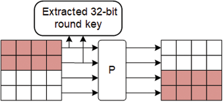
Figure 2: The key schedule of SKINNY
3 The Fault Model and Fault Propagation Analysis of SKINNY
To present a clearer picture of the SKINNY fault attack and the associated issues involved in the propagation of the fault, the following definitions are given.
Definition 1. Suppose that the number of encryption rounds of a cryptographic algorithm A is R, and an attacker injects a fault into the intermediate state data
3.1.1 Random Nibble Fault Injection Model
In this paper, random nibble faults are injected into the SKINNY cipher using software simulation and this model is applied to the study of AFA for this cipher, as detailed in Section 6.1.
(1) The cipher uses the same master key in its operations and the attacker has access to the correct ciphertext data C and the error ciphertext data
(2) A random fault with fault width
3.1.2 Specific Single-Bit Fault Injection Model
This model was implemented based on the THT and combined with AFA to study the security of SKINNY, as detailed in Section 6.2.
(1) See (1) in Section 3.1.1 for details.
(2) A single-bit fault of fault width
3.2 Analysis of the Fault Propagation Process
The length of the basic arithmetic cell of SKINNY is 4 bits, and the differential fault propagation path when
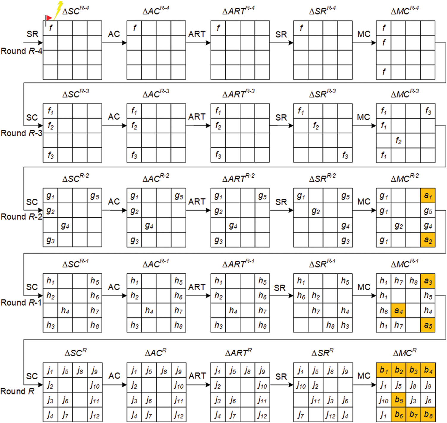
Figure 3: Differential fault propagation process for SKINNY
Definition 2. Let

During SKINNY fault propagation, the output differential value
For
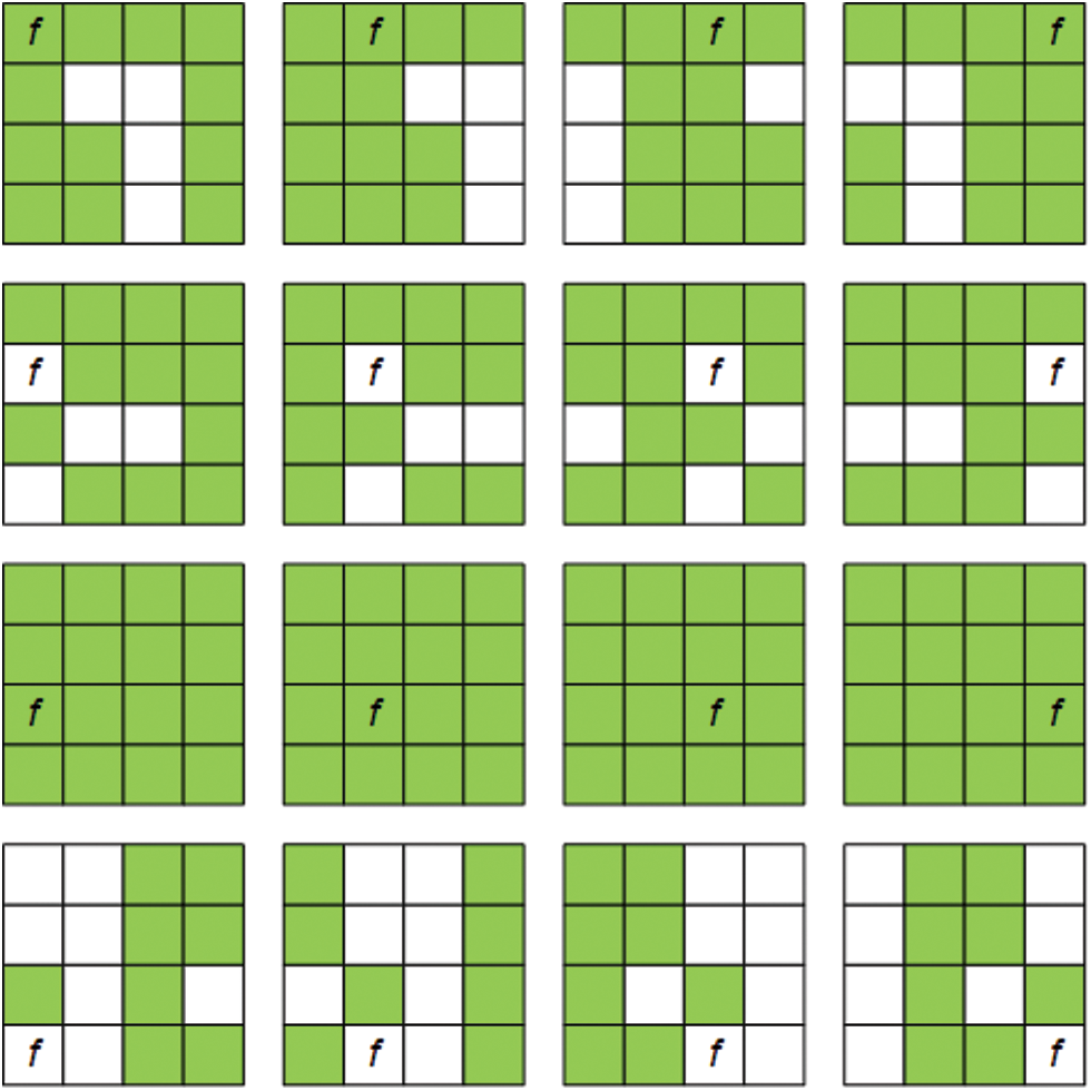
Figure 4: The fault propagation diagram for each fault location in round R-4 for SKINNY
In theory, if a fault can be propagated to all bits of the master key, this key can be fully recovered. As shown in Table 2, when
Interestingly, when a fault is injected
Typically, a HT is designed with two parts: the trigger logic (TL) and the payload logic (PL). Of these, the TL is used to determine if the activation condition is met by a signal line and state value that references the attacker's pre-defined signal line and state value. Once the activation condition is met, the PL performs the corresponding attack (e.g., denial of service, alteration of the original circuit function, or disclosure of secret information, etc.).
4.1 Prerequisites for the Implementation of THT
In this paper, the premises for the design and implementation of the HT circuit are as follows.
(1) SKINNY is implemented as cryptographic IP with certain protections (e.g., sensors from untrusted IP core vendors). The prototype of this cryptographic IP was implemented on a 28 nm Xilinx ZYNQ-7010 FPGA development board. The fact that physical sensors (e.g., temperature sensors) are deployed together with cryptographic IP is a common practice in industrial designs—for example, the LKT4202U [25] security chip. The LKT4202U not only integrates various secure encryption modules (e.g., RSA, DES, AES, etc.) on-chip, but also deploys various physical sensors such as temperature and voltage sensors.
(2) The attacker can insert a HT by directly modifying the design input of the RTL or specific logical elements of the Netlist. In addition, they can only access the Xilinx design language (XDL) [26] file and not the design phase.
(3) Under specific temperature conditions, the HT is activated to flip a specific bit of the intermediate state of the cipher. In this case, the temperature can be changed by a heat gun or a household hair dryer.
The design of the THT is shown in Fig. 5. We have chosen to insert the THT at
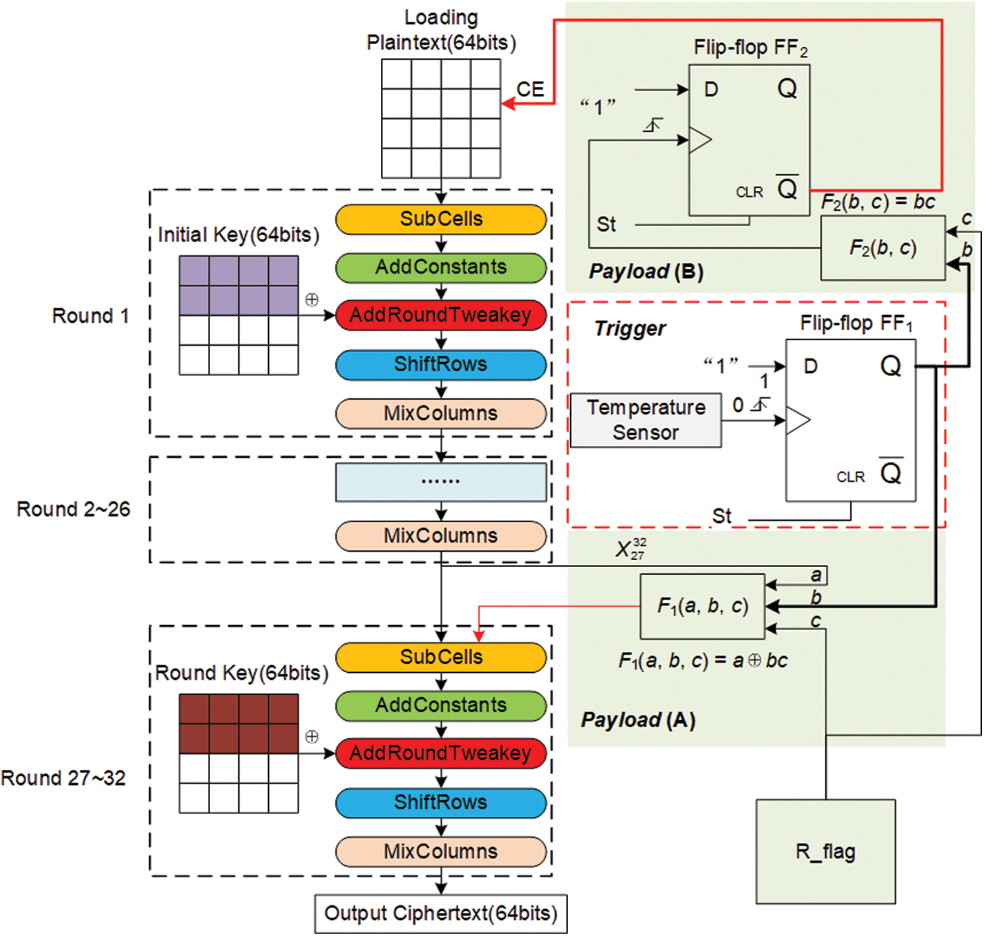
Figure 5: The design of THT
The left part of Fig. 5 shows the encryption process of SKINNY, while the right part shows the designed THT, which consists of two parts: Trigger and Payload. When the temperature detected by the temperature sensor reaches the threshold value set by the attacker, a “1” stored in flip-flop FF1 activates the THT. The payload of the THT consists of two parts: Payload (A) and Payload (B). The three input signals a, b, c of the XOR gate F1(a, b, c) are connected to
In this paper, the THT that we have designed is implemented on a 28 nm Xilinx ZYNQ-7010 FPGA (xc7z010clg400-1), which has an internal integrated temperature sensor that generates a 12-bit temperature output in the range [−273°C, + 230.7°C], e.g., 977 h indicates that the current temperature is +25°C. We directly use the rising edge of the summed 8th- and 9th-bit temperature outputs as the trigger signal for the THT, i.e., the THT is triggered when the on-chip temperature is above the threshold value of +73.34°C (b00 h). An inexpensive heat gun can trigger the THT, and the test platform is shown in Fig. 6, with (1) the 28 nm Xilinx ZYNQ-7010 FPGA development board; (2) the air outlet of the heat gun; and (3) the temperature variations within the chip. The hardware overhead required for the TL implementation is one flip-flop (FF1).
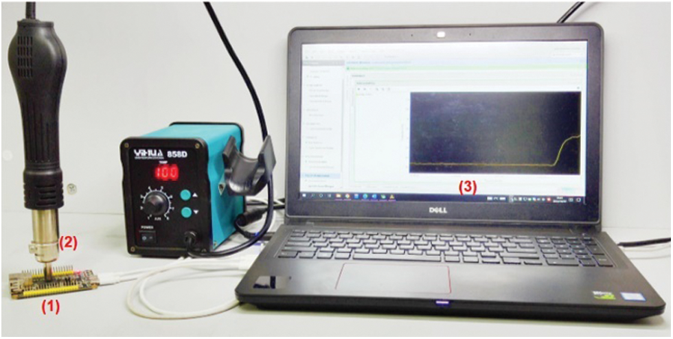
Figure 6: The THT test platform
Suppose, in the k-th encryption process, that Ek and Pk denote the current encryption and the plaintext loaded, respectively. For the same plaintext, a pair of correct and incorrect ciphertexts
4.3 The Hardware Overhead of THT
Cryptographic hardware is mostly provided in the form of third-party IP cores, for which we have designed and packaged our own IP cores for the SKINNY circuit. The basic logic unit of the 28 nm Xilinx ZYNQ-7010 FPGA is the Slice, which contains four 6-input look-up tables (LUTs). We can search the XDL for used LUTs, some of which have three or fewer used inputs, and F1(a, b, c) and F2(b, c) in Fig. 5 can be merged with them, simply by modifying the corresponding Slice instance on the XDL. In summary, the only hardware resources required to implement THT are the two flip-flops (FF1 and FF2). After the THT was inserted into the SKINNY circuit, it was synthesized and implemented using the Vivado 18.3 development tool and verified using the FPGA development board. Compared to the benchmark circuit, the SKINNY circuit with THT inserted only increases the number of flip-flops used by 0.179% and the on-chip power (Dynamic: 1.277 W, Static: 0.112 W) is the same for both, with the hardware resource consumption detailed in Table 3.

When performing AFA on a cipher, building a system of decryption equations from the ciphertext can effectively reduce the solution time. In this section, we give not only the construction of the system of equations for the decryption of SKINNY, but also the algebraic system of equations representation of the fault information.
5.1 Construction of Systems of Algebraic Equations for SKINNY
5.1.1 Algebraic Equation Representation of SC−1
Assuming that the inputs and outputs of a 4-bit S-box are
5.1.2 5.1.2 Algebraic Equation Representation of AC−1
Let
5.1.3 Algebraic Equation Representation of ART−1
In the ART operation, suppose that
5.1.4 Algebraic Equation Representation of SR−1
Suppose that
5.1.5 Algebraic Equation Representation of MC−1
First, in this paper, the inverse matrix M−1 can be derived from the binary matrix M.
Assuming that the 1-bit inputs and outputs of the MC are
5.2 Construction of Systems of Algebraic Equations for Fault Information
In the correct encrypted state, let X be 64 bits of intermediate state data; then, we have
When
Depending on whether the location
In the actual attack environment of cryptographic algorithms, it is difficult for an attacker to determine the exact location of the fault injection. However, the THT that we have designed is capable of precisely achieving bit-level fault injection. In Eq. (9),
In this paper, we use software simulation to perform a random nibble fault injection into SKINNY. In addition, we indicate whether
If
According to Eqs. (10) and (11),
6 The Attack Experiments of SKINNY
In this paper, the software program for SKINNY was written using the C language. In addition, we have used Bosphorus [27] and CryptoMiniSat 5.8.0 [28] for the solution of the algebraic systems of equations, both running on a laptop with an Intel® Core (TM) i5-6300HQ, 2.30 GHz, 8 G RAM and Ubuntu 20.04.2 LTS 64-bit operating system.
We perform random nibble fault injection at the SC input of round 28 of SKINNY. The fault injection in this subsection is implemented through software simulation. For different numbers of fault injections, we conducted 1000 separate attack experiments, the results of which are shown in Fig. 7. When the number of fault injections is N = 1, the residual entropy of the key
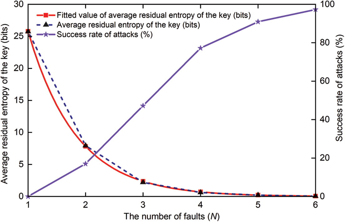
Figure 7: Results of the AFA of SKINNY
In addition, at a confidence level of 95%, we give the results of the fit (shown in the red curve in Fig. 7) based on the actual fault attack results, which is informative and can be represented by Eq. (12).
First, the THT is inserted into the SKINNY circuit at
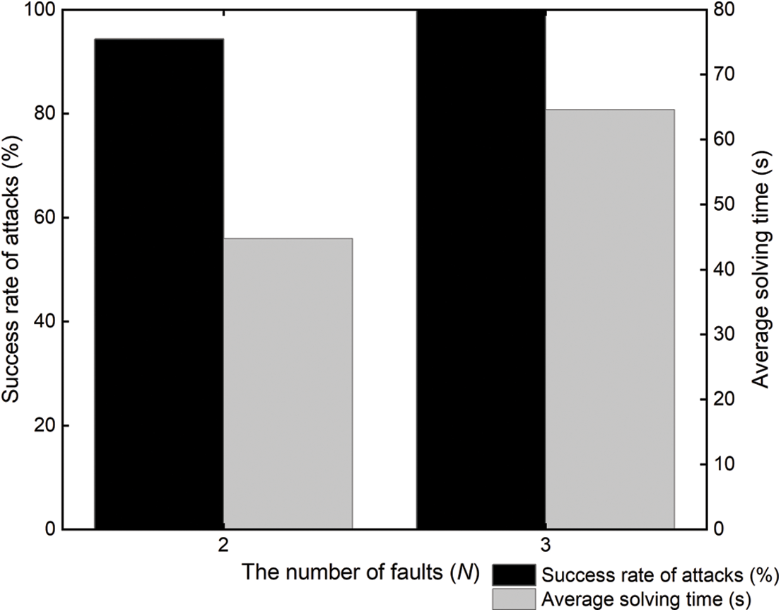
Figure 8: The THT-AFA for SKINNY
The experimental results show that the success rate of the cipher being broken gradually increases as the number of times that the THT is activated increases. However, as the number of algebraic equations required then increases, its solution time also increases. In summary, the optimum number of fault attacks is 3, i.e., the THT is activated 3 times.
The complexity of our proposed THT-AFA method is mainly reflected by the number of fault injections and the solving time of the master key. For different cryptanalysis methods, the efficiency of their attacks is determined by the following factors:
(1) The higher success rate of the attack;
(2) The smaller solving time of the master key;
(3) The deeper the
In fact, using fewer fault injections would be more relevant to the actual attack environment. Table 4 shows the existing works on instance attacks on SKINNY and provides the relationship between the precondition, the fault models, the number of faults, the average solution time, and the success rate for various methods. Vafaei et al. [29] successfully performed differential fault analysis (DFA) on SKINNY using approximately 10 faults (2–3 faults injected at each of 4 different locations). Xu et al. [30] performed an enhanced persistent fault analysis (EPFA) of SKINNY with the required number of faults of 1500–1600. In [31], the authors not only performed algebraic persistent fault analysis of SKINNY based on known plaintexts (KP-APFA), but also combined S-box decomposition with constraint-based algebraic fault analysis (SD-APFA) to achieve a security analysis of SKINNY. Although some attacks were as low as 26.17 s, they used five times as many faults as we did. In a comprehensive comparison, our proposed THT-AFA can recover the master key of SKINNY with the least number of faults and less time.

In this paper, a THT-AFA method is proposed for the SKINNY cipher. We design a THT, which is implemented on a 28 nm Xilinx ZYNQ-7010 FPGA development board with a hardware overhead of only 2 flip-flops. We can change the temperature inside the main chip of this FPGA development board with a hot air gun. The THT is triggered when the temperature inside the chip reaches the threshold that we set, thus performing a bit-level fault injection into SKINNY. In addition, we performed an AFA of the SKINNY cipher under the random nibble fault injection model. When the number of random nibble faults reached 6, the residual entropy of the key for this cipher was reduced to 0.058 bits on average, and the success rate of its attack was only 97.3%. The master key of SKINNY can be recovered with a 100% success rate by flipping the bit at
Acknowledgement: We would like to thank the handling editor and the anonymous reviewers for their careful reading and helpful remarks.
Funding Statement: This paper was supported in part by the Natural Science Foundation of Heilongjiang Province of China (Grant No. LH2022F053), in part by the Scientific and technological development project of the central government guiding local (Grant No. SBZY2021E076), in part by the Postdoctoral Research Fund Project of Heilongjiang Province of China (Grant No. LBH-Q21195), in part by the Fundamental Research Funds of Heilongjiang Provincial Universities of China (Grant No. 145209146), and in part by the National Natural Science Foundation of China (NSFC) (Grant No. 61501275).
Conflicts of Interest: The authors declare that they have no conflicts of interest to report regarding the present study.
1For convenience, SKINNY-64-64 is represented by SKINNY for the rest of the paper.
References
1. C. Beierle, J. Jean, S. Kölbl, G. Leander, A. Moradi et al., “The skinny family of block ciphers and its low-latency variant mantis,” in Proc. CRYPTO 2016, Santa Barbara, CA, USA, pp. 123–153, 2016. [Google Scholar]
2. A. Barenghi, G. Bertoni, E. Parrinello and G. Pelosi, “Low voltage fault attacks on the RSA cryptosystem,” in Proc. FDTC 2009, Lusanne, Switzerland, pp. 23–31, 2009. [Google Scholar]
3. A. Barenghi, G. M. Bertoni, L. Breveglieri, M. Pellicioli and G. Pelosi, “Low voltage fault attacks to AES,” in Proc. HOST 2010, Anaheim, CA, USA, pp. 7–12, 2010. [Google Scholar]
4. C. H. Kim and J. J. Quisquater, “Fault attacks for CRT based RSA: New attacks, new results, and new countermeasures,” in Proc. WISTP 2007, Heraklion, Crete, Greece, pp. 215–228, 2007. [Google Scholar]
5. J. Rodriguez, A. Baldomero, V. Montilla and J. Mujal, “LLFI: Lateral laser fault injection attack,” in Proc. FDTC 2019, Atlanta, GA, USA, pp. 41–47, 2019. [Google Scholar]
6. T. Korak, “Investigation of parameters influencing the success of optical fault attacks,” in Proc. FPS 2013, La Rochelle, France, pp. 140–157, 2013. [Google Scholar]
7. N. Theißing, D. Merli, M. Smola, F. Stumpf and G. Sigl, “Comprehensive analysis of software countermeasures against fault attacks,” in Proc. DATE 2013, Grenoble, France, pp. 404–409, 2013. [Google Scholar]
8. J. Breier, D. Jap, X. Hou, S. Bhasin and Y. Liu, “SNIFF: Reverse engineering of neural networks with fault attacks,” IEEE Transactions on Reliability, vol. 71, no. 4, pp. 1527–1539, 2022. https://doi.org/10.1109/TR.2021.3105697 [Google Scholar] [CrossRef]
9. A. Barenghi, L. Breveglieri, I. Koren and D. Naccache, “Fault injection attacks on cryptographic devices: Theory, practice, and countermeasures,” Proceedings of the IEEE, vol. 100, no. 11, pp. 3056–3076, 2012. https://doi.org/10.1109/JPROC.2012.2188769 [Google Scholar] [CrossRef]
10. R. S. Chakraborty, I. Saha, A. Palchaudhuri and G. K. Naik, “Hardware trojan insertion by direct modification of FPGA configuration bitstream,” IEEE Design & Test, vol. 30, no. 2, pp. 45–54, 2013. https://doi.org/10.1109/MDT.2013.2247460 [Google Scholar] [CrossRef]
11. J. Zhang and Q. Xu, “On hardware trojan design and implementation at register-transfer level,” in Proc. HOST 2013, Austin, TX, USA, pp. 107–112, 2013. [Google Scholar]
12. S. Mal-Sarkar, A. Krishna, A. Ghosh and S. Bhunia, “Hardware trojan attacks in fpga devices: Threat analysis and effective counter measures,” in Proc. GLSVLSI ’14, Houston, Texas, USA, pp. 287–292, 2014. [Google Scholar]
13. T. Hoque, X. Wang, A. Basak, R. Karam and S. Bhunia, “Hardware trojan attacks in embedded memory,” in Proc. VTS 2018, San Francisco, CA, USA, pp. 1–6, 2018. [Google Scholar]
14. J. Clements and Y. Lao, “Hardware trojan design on neural networks,” in Proc. ISCAS 2019, Sapporo, Japan, pp. 1–5, 2019. [Google Scholar]
15. J. Ye, Y. Hu and X. Li, “Hardware trojan in FPGA CNN accelerator,” in Proc. ATS 2018, Hefei, China, pp. 68–73, 2018. [Google Scholar]
16. M. H. Khan, R. Gupta, J. Jose and S. Nandi, “Dead flit attack on NoC by hardware trojan and its impact analysis,” in Proc. NoCArc ’21, Athens, Greece, pp. 10–15, 2021. [Google Scholar]
17. S. Bhasin, J. L. Danger, S. Guilley, X. T. Ngo, L. Sauvage et al., “Hardware trojan horses in cryptographic IP cores,” in Proc. FDTC 2013, Los Alamitos, CA, USA, pp. 15–29, 2013. [Google Scholar]
18. D. Knichel, T. Moos and A. Moradi, “The risk of outsourcing: Hidden SCA trojans in third-party IP-cores threaten cryptographic ICs,” in Proc. ETS 2020, Tallinn, ESTONIA, pp. 1–6, 2020. [Google Scholar]
19. M. Hutter and J. M. Schmidt, “The temperature side channel and heating fault attacks,” in Proc. CARDIS 2013, Berlin, Germany, pp. 219–235, 2013. [Google Scholar]
20. R. Kumar, P. Jovanovic and I. Polian, “Precise fault-injections using voltage and temperature manipulation for differential cryptanalysis,” in Proc. IOLTS 2014, Platja d’Aro, Spain, pp. 43–48, 2014. [Google Scholar]
21. P. Dash, C. Perkins and R. M. Gerdes, “Remote activation of hardware trojans via a covert temperature channel,” in Proc. SecureComm 2015, Dallas, TX, USA, pp. 294–310, 2015. [Google Scholar]
22. S. Ghandali, D. Holcomb and C. Paar, “Temperature-based hardware trojan for ring-oscillator-based TRNGs,” arXiv preprint arXiv:1910.00735, 2019. [Google Scholar]
23. N. T. Courtois, K. Jackson and D. Ware, “Fault-algebraic attacks on inner rounds of DES,” in Proc. E-Smart ’10, Montreuil, France, pp. 1–59, 2010. [Google Scholar]
24. Internet, “7 Series FPGAs and Zynq-7000 SoC XADC Dual 12-Bit 1 MSPS Analog-to-Digital Converter User Guide (UG480),” [Online]. Available: https://docs.xilinx.com/r/en-US/ug480_7Series_XADC/7-Series-FPGAs-and-Zynq-7000-SoC-XADC-Dual-12-Bit-1-MSPS-Analog-to-Digital-Converter-User-Guide-UG480. (accessed on 28 September 2022). [Google Scholar]
25. Internet, “LKT4202U,” [Online]. Available: http://www.bjlcs-tech.com/article/226.html. (accessed on 30 December 2022). [Google Scholar]
26. C. Beckhoff, D. Koch and J. Torresen, “The Xilinx Design Language (XDLTutorial and use cases,” in Proc. ReCoSoC 2011, Montpellier, Francepp, pp. 1–8, 2011. [Google Scholar]
27. D. Choo, M. Soos, K. M. A. Chai and K. S. Meel, “Bosphorus: Bridging ANF and CNF solvers,” in Proc. DATE 2019, Florence, Italy, pp. 468–473, 2019. [Google Scholar]
28. Internet, “Cryptominisat 5.8.0,” [Online]. Available: https://github.com/msoos/cryptominisat/releases. (accessed on 31 December 2022). [Google Scholar]
29. N. Vafaei, S. Saha, N. Bagheri and D. Mukhopadhyay, “Fault attack on SKINNY cipher,” Journal of Hardware and Systems Security, vol. 4, no. 4, pp. 277–296, 2020. https://doi.org/10.1007/s41635-020-00103-z [Google Scholar] [CrossRef]
30. G. Xu, F. Zhang, B. Yang, X. Zhao, W. He et al., “Pushing the limit of PFA: Enhanced persistent fault analysis on block ciphers,” IEEE Transactions on Computer-Aided Design of Integrated Circuits and Systems, vol. 40, no. 6, pp. 1102–1116, 2021. https://doi.org/10.1109/TCAD.2020.3048280 [Google Scholar] [CrossRef]
31. X. Fang, H. Zhang, D. Wang, H. Yan, F. Fan et al., “Algebraic persistent fault analysis of SKINNY_64 based on S_Box decomposition,” Entropy, vol. 24, no. 11, pp. 1508, 2022. https://doi.org/10.3390/e24111508 [Google Scholar] [PubMed] [CrossRef]
Cite This Article
 Copyright © 2023 The Author(s). Published by Tech Science Press.
This work is licensed under a Creative Commons Attribution 4.0 International License , which permits unrestricted use, distribution, and reproduction in any medium, provided the original work is properly cited.


 Submit a Paper
 Propose a Special lssue
 View Full Text
 Download PDF
 Downloads
 Citation Tools