
 Submit a Paper
 Propose a Special lssue
 Open Access
ARTICLE

A Novel Compact Highly Isolated UWB MIMO Antenna with WLAN Notch
1 Department of Electrical Engineering, University of Engineering and Technology, Peshawar, 25000, Pakistan
2 Department of Electrical Engineering, University of Science and Technology, Bannu, 28100, Pakistan
3 Department of Electrical Engineering, College of Engineering Taif University,
Al-Hawiyah, Taif, P.O. Box 888, Saudi Arabia
4 Department of Electrical Engineering, College of Engineering, Taif University, P.O. Box 11099, Taif, 21944, Saudi Arabia
* Corresponding Author: Nasim Ullah. Email:
Computers, Materials & Continua 2023, 75(1), 669-681. https://doi.org/10.32604/cmc.2022.033939
Received 01 July 2022; Accepted 07 September 2022; Issue published 06 February 2023
 View Full Text
 Download PDF
Abstract
This paper presents a compact Multiple Input Multiple Output (MIMO) antenna with WLAN band notch for Ultra-Wideband (UWB) applications. The antenna is designed on 0.8 mm thick low-cost FR-4 substrate having a compact size of 22 mm × 30 mm. The proposed antenna comprises of two monopole patches on the top layer of substrate while having a shared ground on its bottom layer. The mutual coupling between adjacent patches has been reduced by using a novel stub with shared ground structure. The stub consists of complementary rectangular slots that disturb the surface current direction and thus result in reducing mutual coupling between two ports. A slot is etched in the radiating patch for WLAN band notch. The slot is used to suppress frequencies ranging from 5.1 to 5.9 GHz. The results show that the proposed antenna has a very good impedance bandwidth of |S11| < −10 dB within the frequency band from 3.1–14 GHz. A low mutual coupling of less than −23 dB is achieved within the entire UWB band. Furthermore, the antenna has a peak gain of 5.8 dB, low ECC < 0.002 and high Diversity Gain (DG > 9.98).Keywords
Owing to the requirements of higher data rates, mobile networks require a larger spectrum to fulfill these demands. Therefore, MIMO antenna becomes the center of attention. As the name suggests, multiples antennas are used for transmission and reception to increase data rate and channel capacity [1]. When multiple antennas are placed within a close proximity, it results in increasing mutual coupling among the adjacent antennas and thus causes performance degradation of overall MIMO antenna system. This issue becomes worse when we increase the number of radiators in a MIMO antenna design. Designing an efficient antenna with enhanced isolation and improved MIMO performance is the requirement of emerging communication technologies.
Various techniques have been used for isolation enhancement such as Defected Ground Structure (DGS) [2,3], Electromagnetic band gap (EBG) [4–7], Parasitic Element [8–11], complementary split ring resonators [12–14], metallic stubs and shorting pins [15–18], and neutralization line [19,20]. For instance, in [2], S-Shape periodic defected ground structure (PDGS) is used for coupling reduction. The proposed PDGS reduces the mutual coupling by 40 dB in a narrowband. Moreover, isolation can also be improved by making multiple rectangular shape DGS in between patch antennas [3]. In [4], EBG is used in the ground plane for improving isolation between patch antennas. A novel EBG is etched in the ground plane to stop EM waves propagation in a particular band. The results show a reduced mutual coupling of around 10 dB in the operating band. In [5], mutual coupling has been reduced by using uni planar EBG in between two radiators. The use of EBG reduces the mutual coupling by 20 dB in a narrowband of 5.8 GHz. A double layer twin patch EBG (DLDP-EBG) is used in [6] for coupling reduction. It is observed that it helps in reducing mutual coupling at the frequency range of 4–6 GHz by approximately 5 to 30 dB. In [7] EBG and DGS technique are used together for isolation enhancement. The DGS helps in reducing mutual coupling for more than 25 dB in the entire UWB range and EBG reduces the coupling effect by 10 dB in the frequency range of 4–5 GHz. The overall size of this antenna is 26 × 31 mm2. The use of parasitic structure is also commonly used for coupling reduction. In [8], a circular parasitic element is used in the ground plane. This helps in creating reverse coupling. A 67 × 67 mm2 size of antenna reduces mutual coupling to −20 dB. Moreover, mutual coupling is also reduced by using fan shape decoupler [9], in [10] a rectangular parasitic element is inserted between radiators for mutual coupling reduction. Moreover in [11] novel design parasitic structure is used to have isolation enhancement. In addition, Complementary Split Ring Resonator (CSSR) also helps in reduction of mutual coupling. In [12] the use of CSRR reduces the mutual coupling by more than 10 dB. In [13,14], folded split ring resonator (FSRR) is used for isolation enhancement. A slotted strip has been used in [15] for coupling reduction. In [16], six metallic pins are connected at the edges of patch antenna. These pins act as reflector and thus suppress the signal coming from adjacent patch. Moreover, [17,18] metallic stub technique has been used for isolation enhancement. In [19,20] neutralization line technique has been proved to be an effective method for coupling reduction. Moreover, Frequency Selective Surface (FSS) is also used for introducing a band stop and gain enhancement in the UWB antenna [21,22]. The FSS is a two-dimensional, thin periodic array that demonstrates its filtering properties to transmit (band pass) and/or reflect (stop band) electromagnetic waves (EMW). Similarly, a compact size planar antenna for wideband 5G communication utilizing low transmission loss and high gain is presented [23,24].
In past different topologies of MIMO systems were investigated. The antennas were placed in mutually optimized positions to achieve the highest isolation. In addition, multiple techniques have been investigated that helps in the reduction of mutual coupling in MIMO antenna. Based on above discussion it can be concluded that reducing mutual coupling in a compact size is a challenging problem in antenna design. In this paper, a new compact microstrip feed MIMO antenna is proposed. The patch slots are included in the radiating surface for filtering of WLAN band. A Complementary stub is protruded in the ground plane of MIMO antenna for achieving high isolation and greater impedance bandwidth. Although, the use of slot in the patch for band suppression is common but is difficult to implement in a compact design.
Most of the proposed models reduce the mutual coupling at the cost of increasing the overall size of MIMO antenna. Similarly, EBG and other techniques reduce the mutual coupling only in a narrowband. However, this research work proposes a compact MIMO antenna design that contributes to reduce the mutual coupling by more than 23 dB in the whole UWB range and suppresses WLAN band. This paper proposes a novel antenna operating in the UWB band while suppressing 5.1–5.9 GHz (WLAN) inference in the UWB spectrum. A novel slotted stub is placed in the ground that helps to design a compact UWB MIMO antenna with high isolation. The simulated and measured results have confirmed that the proposed design is operating in the UWB band with stable radiation pattern, high gain, low envelope correlation, improve Directivity gain and significant isolation. Thus, the proposed antenna has a best trade-off performance and can be a suitable candidate for MIMO systems.
The proposed antenna design is presented in Fig. 1. The overall size of antenna is 22 × 30 mm2. The antenna is designed using easily available FR-4 substrate (
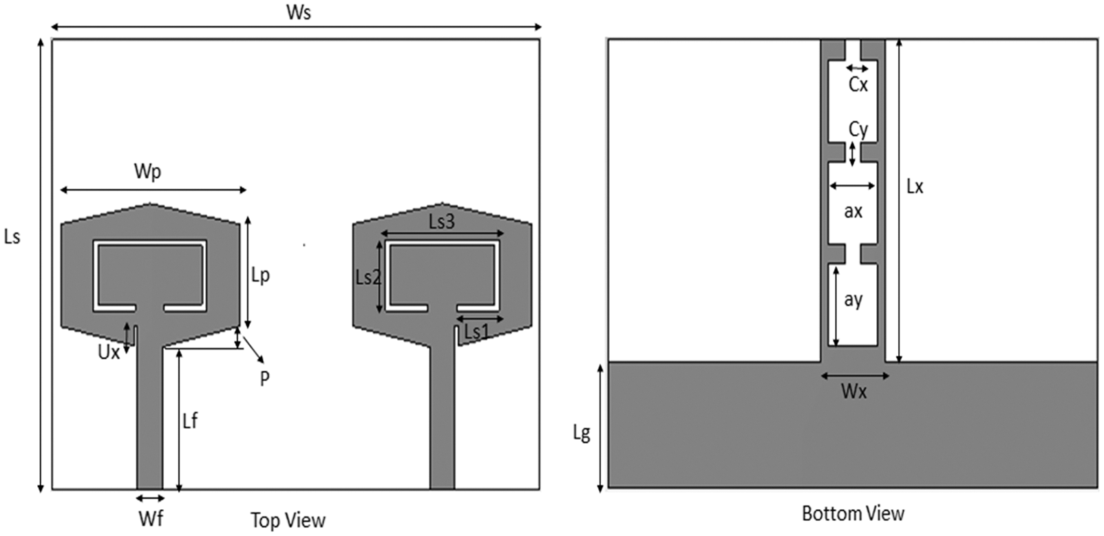
Figure 1: Proposed antenna design
The initial design of MIMO antenna is based on Eq. (1) [7].
In Eq. (1),
The final design is achieved by the evolution of proposed antenna through different stages as shown is Fig. 2. In Fig. 2, Antenna 1 shows the MIMO antenna with partial ground structure, Antenna 2 consists of stub with complementary slots in it. In Antenna 3 a slot is etched in the patch for creating WLAN band notch [25]. These slots act as resonators and help in suppressing the desirable frequency band. The desired band notch feature can be obtained by adjusting the length and the width of the slot. The length and width of the slot is based on Eq. (2) [25]. The overall length of the slot approximates to
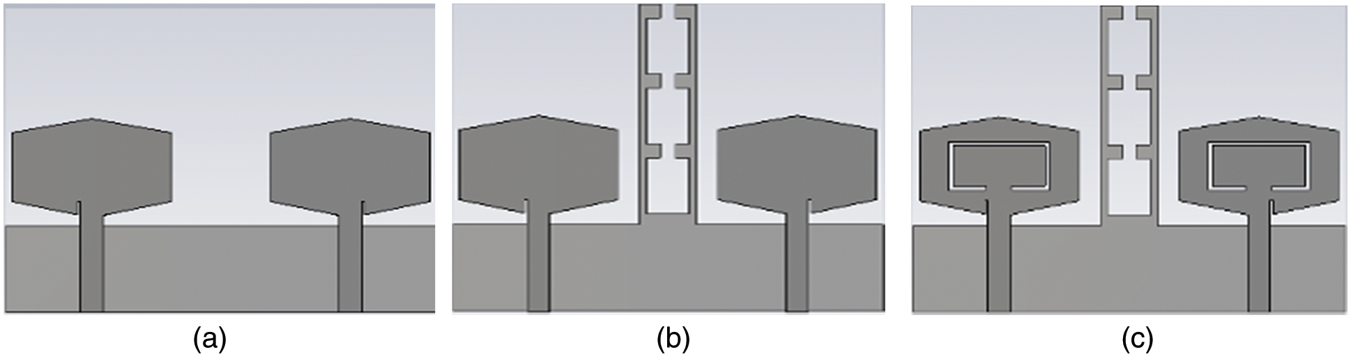
Figure 2: Evolution of MIMO antenna, (a) antenna 1 (without stub) (b) antenna 2 (with stub) (c) antenna 3 (with stub and notch)
Here,
The proposed antenna is designed for the UWB application. In Fig. 3a it is evidently clear that Antenna 1 has low impedance bandwidth to cover the UWB band, Antenna 2 operates in the UWB range while Antenna 3 operates in the UWB and suppress the WLAN band. Furthermore, Fig. 3b shows that the Antenna 1 operates with high mutual coupling. Antenna 2 and Antenna 3 results show reduced mutual coupling to within the acceptable range due to DGS technique.
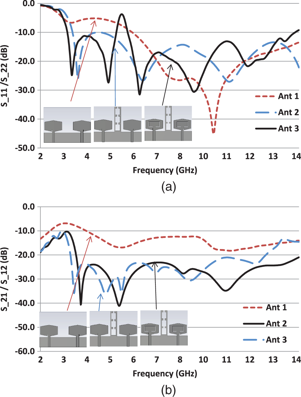
Figure 3: (a) S11/S22 simulated results (b) S12/S21 simulated results
The optimized parameters of proposed MIMO antenna are obtained by complete parametric analysis of design dimensions. These parameters include antenna ground length “Lg” that has been varied from 5.6 to 6.2 mm Moreover, length of the notch “Ls3” is also changed from 6 to 6.6 mm. The final optimized parameters of proposed antenna are presented in Table 1.
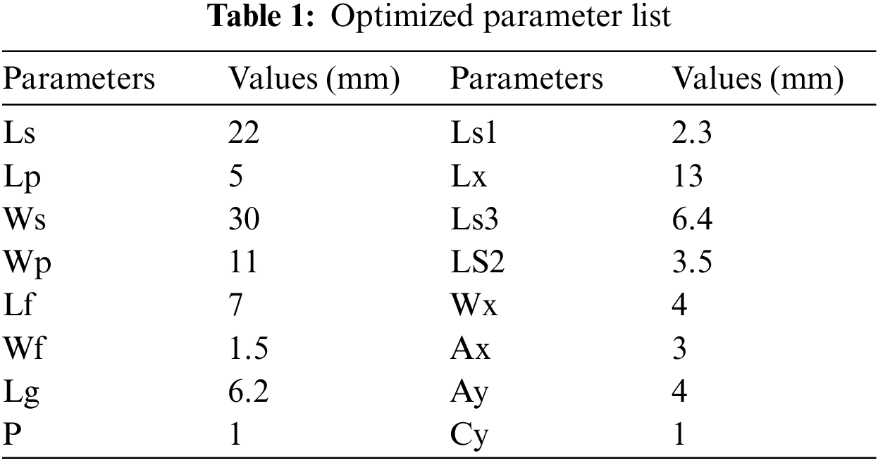
Fig. 4 shows the parametric results of ‘Lg’ parameter. ‘Lg’ is the length of the ground. By using parametric sweep, the proposed antenna showed optimized impedance bandwidth at Lg = 6.2 mm
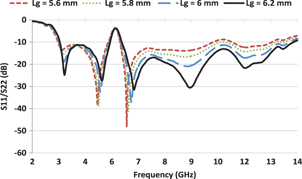
Figure 4: Parametric results of Lg parameter
The parametric analysis of slot length LS3 has been studied and the results are shown in Fig. 5. It is obvious that varying the length of the slot has negligible effect on the impedance bandwidth.
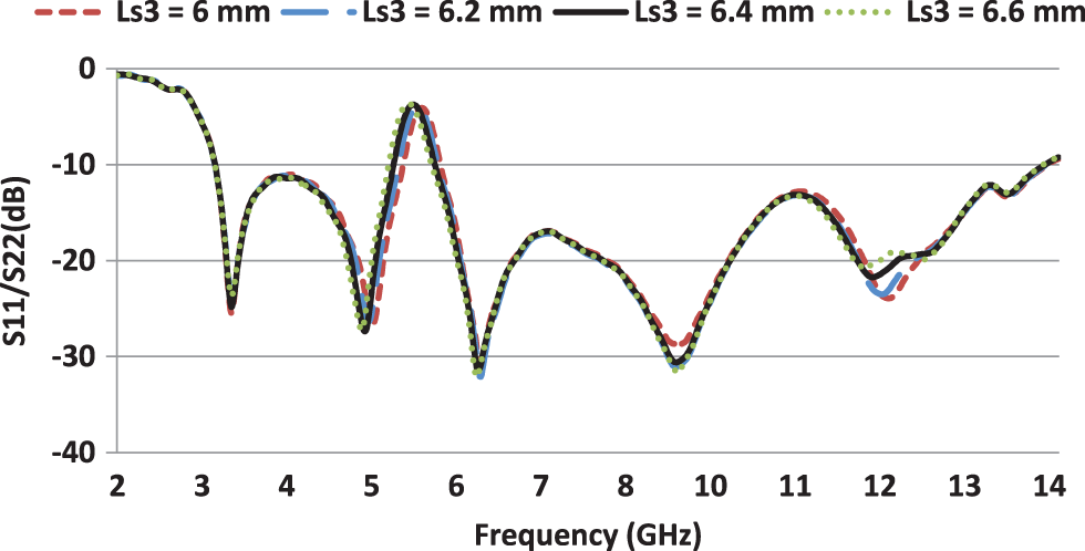
Figure 5: Parametric analysis of slot length L3
The antenna current distribution is obtained by simulating it for three different frequencies i.e., 3.9, 7.4 and 10.5 GHz. Fig. 6 shows the current density of proposed antenna with and without stub. It can be seen that rectangular stub provided alternate current path and thus enhanced the isolation between two radiating patches.
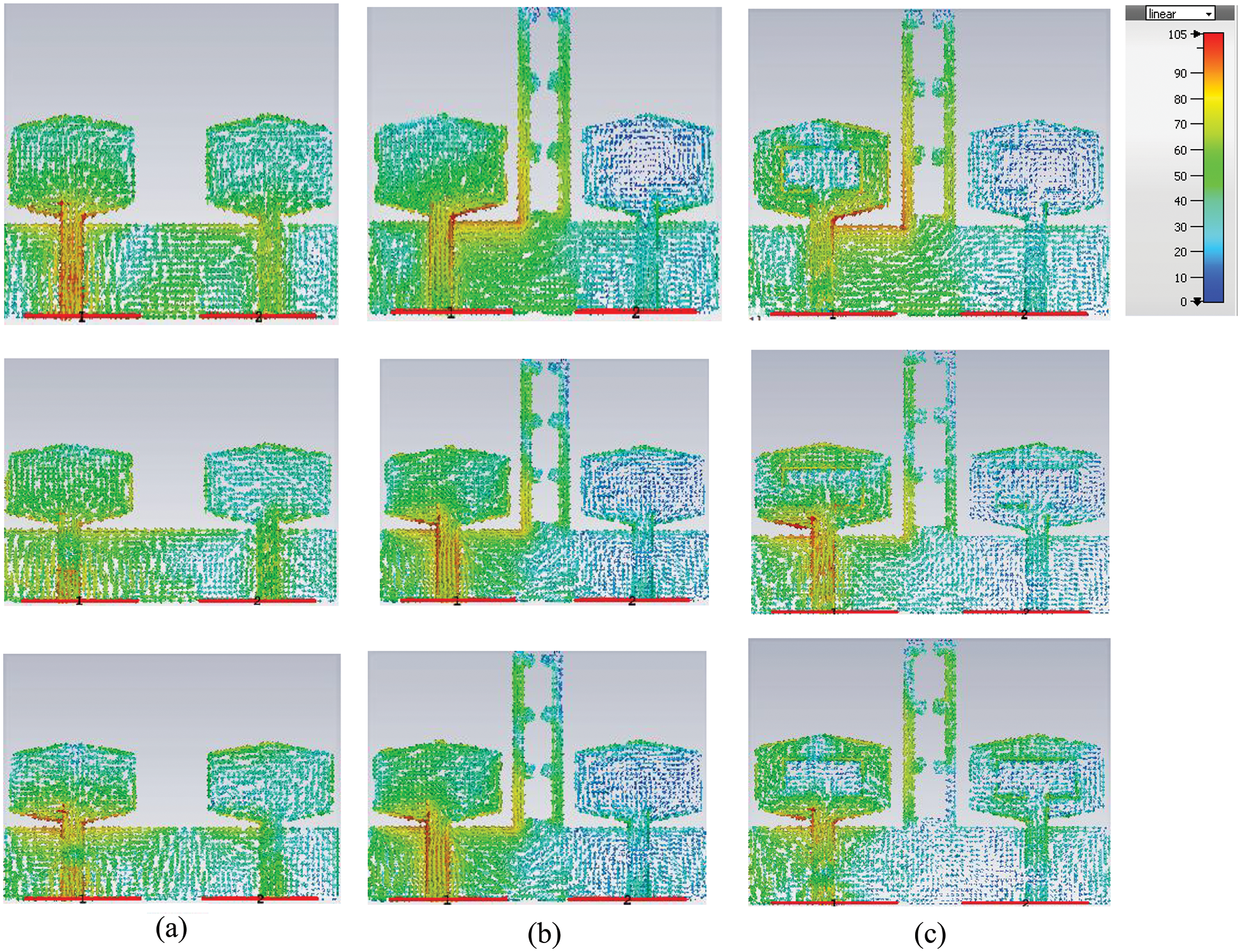
Figure 6: Current surface distribution at (a) 3.9 GHz, (b) 7.4 GHz (c) 10.5 GHz
The proposed antenna is optimized after parametric study then the optimized dimensions are used to fabricate the proposed design. Fig. 7 shows the prototype of fabricated antenna.
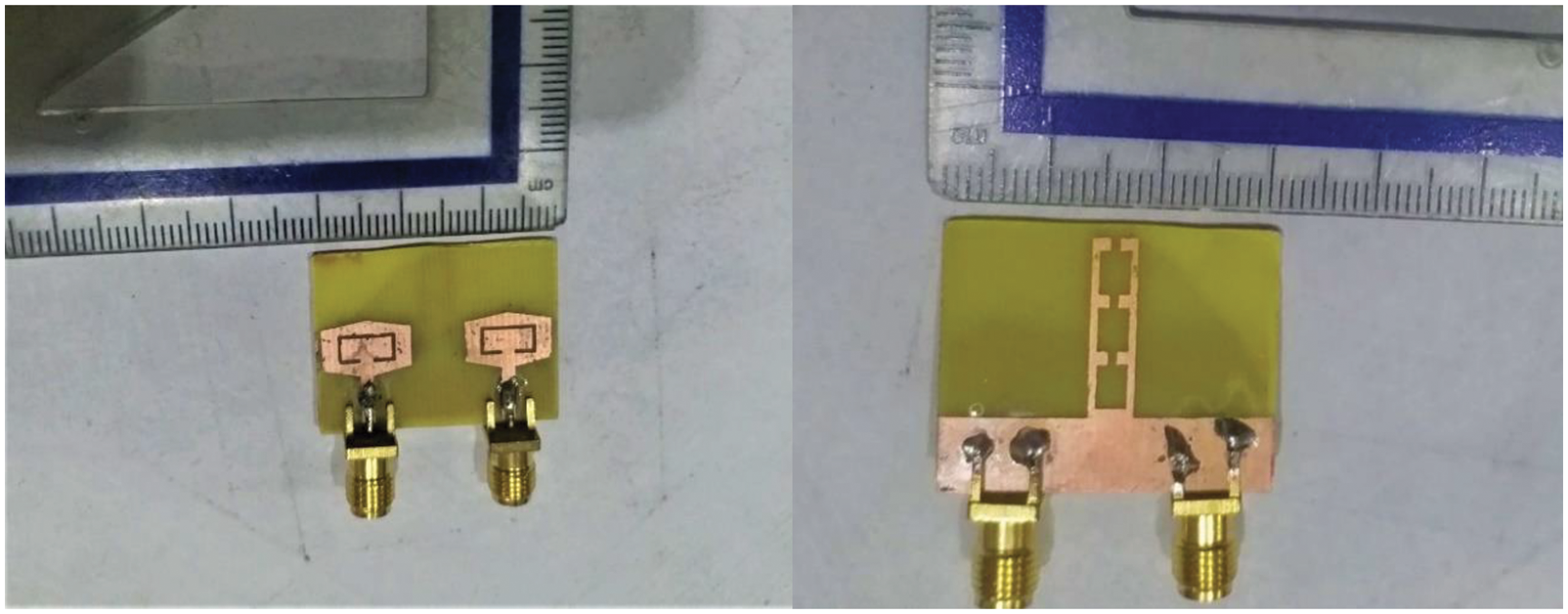
Figure 7: Fabricated design, top view (left) bottom view (right)
The reflection coefficient (S11/S22) and transmission coefficient (S12/S21) of fabricated model has been measured using Vector Network Analyzer. It is evidently clear from Fig. 8 that the measurement and simulation results are closely matched. The S11/S22 < −10 dB in the whole UWB range except a notch from 5 to 6 GHz to suppress WLAN band. In addition, the transmission coefficient (S12/S21 < −23 dB) also indicates that antennas have very low mutual coupling between each other despite compact size.
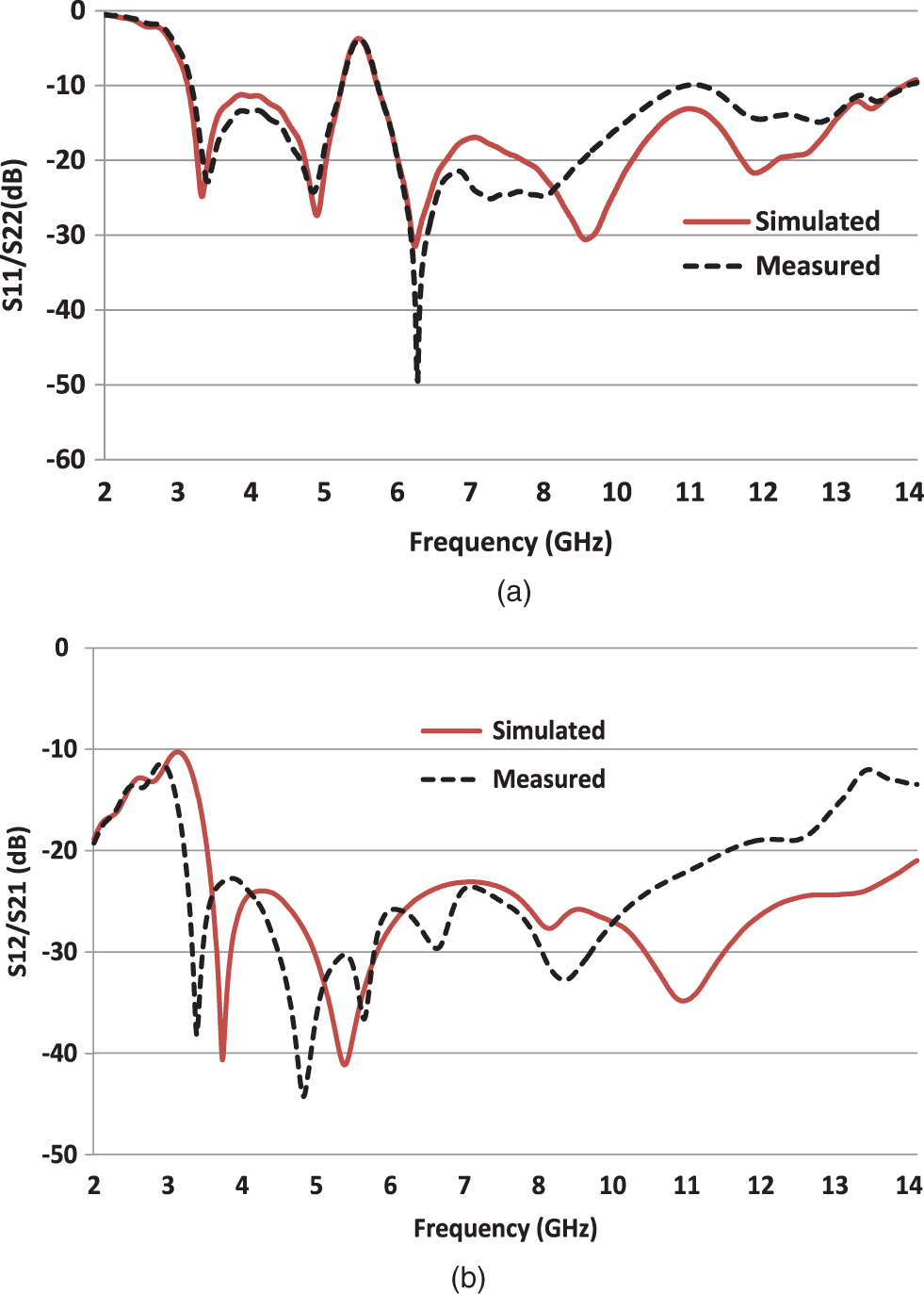
Figure 8: Simulated and measured results (a) S11/S22 (b) S21/S12
In Fig. 9, the fabricated antenna is placed in an Anechoic Chamber to measure its performance characteristics. The designed MIMO antenna radiation pattern is also measured at different frequency points i.e., at lower frequency (3.9 GHz), center frequency (6.4 GHz) and higher frequency (9.6 GHz). Fig. 10 shows the simulated and measured results of radiation pattern of proposed design. It can be observed that antenna has omni directional pattern at lower frequency. However, it shows quasi-omnidirectional behavior at higher frequency.
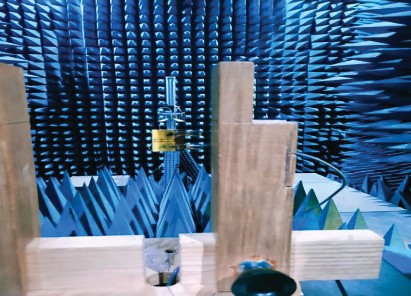
Figure 9: Proposed antenna testing
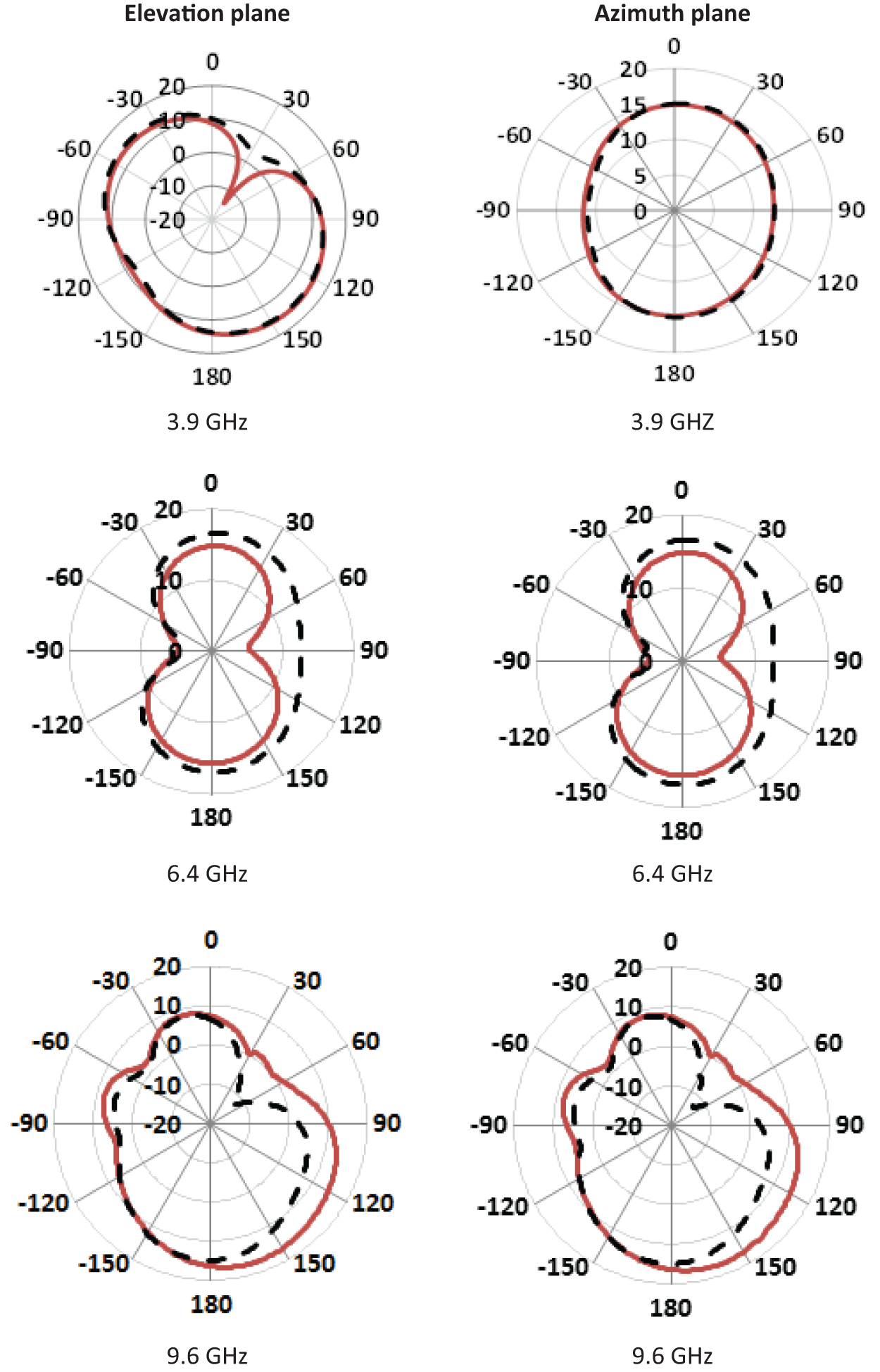
Figure 10: Radiation pattern at (i) 3.9 GHz (ii) 6.4 GHz and (iii) 9.6 GHz
The antenna gain, radiation efficiency and total efficiency results are presented in Fig. 11. This shows that antenna has a peak gain of 5.8 dB and an overall efficiency greater than 80%. In addition, Envelope co-relation co-efficient (ECC) and diversity gain of MIMO antenna was calculated and compared with simulated results. The ECC parameter shows the correlation among the MIMO antenna elements. The lower value of ECC shows that antennas are independent of each other. The ideal value of ECC should be ‘0’. Fig. 12 shows that ECC of the proposed antenna is less than 0.002. Moreover, the value of Diversity gain is also calculated and is greater than 9.96.
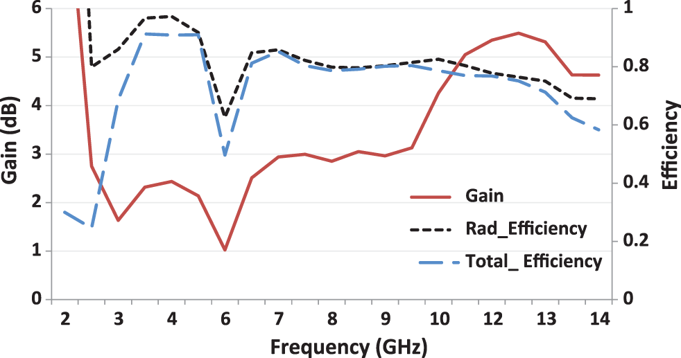
Figure 11: Simulated results of gain, radiation efficiency and total efficiency
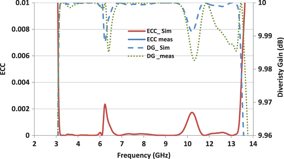
Figure 12: Simulated/measured results of ECC and diversity gain
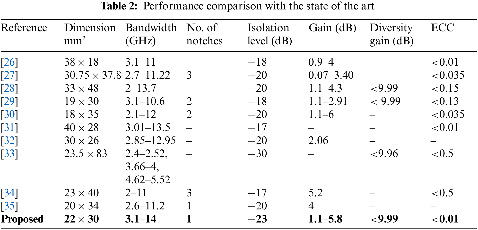
In Table 2, the performance comparison of proposed antenna with that of previous research work is presented. This table compares the performance in terms of overall size, impedance bandwidth, mutual coupling, gain, ECC and Diversity gain. It can be concluded that the proposed antenna performance fulfills the requirement of UWB systems with significant rejection of narrowband systems using a compact size.
A compact (22 mm2 × 30 mm2) MIMO antenna with WLAN band notch is presented in this research paper. The antenna operates in the frequency band ranging from 3.1–14 GHz covering the whole UWB range. The antenna has low mutual coupling (<−23 dB) in the whole UWB band. A ground stub of complementary rectangular shape is used in the proposed antenna. The antenna shows peak gain of 5.8 dB and a radiation efficiency of more than 80%. Moreover, slot is used in the patch for WLAN band (5.1–5.9) GHz suppression. In addition, other MIMO parameters are also obtained i.e., low ECC < 0.002 and high Diversity gain > 9.98. All above performance parameters make the proposed MIMO antenna a suitable candidate for UWB applications.
Funding Statement: The authors would like to acknowledge the support from Taif University Researchers Supporting Project Number (TURSP-2020/264), Taif University,
Conflicts of Interest: The authors state that they have no financial or other conflicts of interest to disclose with connection to this research.
References
1. M. A. T. Alrubei, I. A. Alshimaysawe, A. N. Hassan and A. H. K. Khwayyir, “Capacity analysis & performance comparison of SISO, SIMO, MISO & MIMO systems,” Journal of Physcis: Conference Series, vol. 1530, no. 1, pp. 012077, 2020. [Google Scholar]
2. K. Wei, J. Li, L. Wang, Z. Xing and R. Xu, “S-Shaped periodic defected ground structures to reduce microstrip antenna array mutual coupling,” Electronics Letter, vol. 52, no. 15, pp. 1288–1290, 2016. [Google Scholar]
3. A. Habashi, J. Nourinia and C. Ghobadi, “A rectangular defected ground structure (DGS) for reduction of mutual coupling between closely-spaced microstrip antennas,” in ICEE 2012–20th Iranian Conf. on Electrical Engineering, Tehran, Iran, pp. 1347–1350, 2012. [Google Scholar]
4. O. Sokunbi and H. Attia, “Dual-layer dual-patch EBG structure for isolation enhancement and correlation reduction in MIMO antenna arrays,” Progress in Electromagnetics Research C, vol. 100, no. November 2019, pp. 233–245, 2020. [Google Scholar]
5. S. Ghosh, T. N. Tran and T. Le-Ngoc, “Dual-layer EBG-based miniaturized multi-element antenna for MIMO systems,” IEEE Transactions on Antennas Propagation, vol. 62, no. 8, pp. 3985–3997, 2014. [Google Scholar]
6. T. Dabas, D. Gangwar, B. K. Kanaujia and A. K. Gautam, “Mutual coupling reduction between elements of UWB MIMO antenna using small size uniplanar EBG exhibiting multiple stop bands,” AEU–Interantional Journal of Electronics and Communications, vol. 93, pp. 32–38, 2018. [Google Scholar]
7. A. Khan, S. Bashir, S. Ghafoor and K. K. Qureshi, “Mutual coupling reduction using ground stub and EBG in a compact wideband MIMO antenna,” IEEE Access, vol. 9, pp. 40972–40979, 2021. [Google Scholar]
8. J. Ghimire, K. Choi and D. Choi, “Bandwidth enhancement and mutual coupling reduction using a notch and a parasitic structure in a UWB-MIMO antenna,” International Journal of Antennas and Propagation, vol. 2019, pp. 1–9, 2019. [Google Scholar]
9. M. M. Hassan, M. Rasool, M. U. Asghar, Z. Zahid, A. A. Khan et al., “A novel UWB MIMO antenna array with band notch characteristics using parasitic decoupler characteristics using parasitic decoupler,” Journal of Electromagnetic Waves and Applications, vol. 5071, pp. 1225–1238, 2019. [Google Scholar]
10. T. Addepalli and V. R. Anitha, “A very compact and closely spaced circular shaped UWB MIMO antenna with improved isolation,” AEU–Interantional Journal of Electronics and Communications, vol. 114, pp. 153016, 2020. [Google Scholar]
11. Z. Li, Z. Du, M. Takahashi, S. Member and K. Saito, “Reducing mutual coupling of MIMO antennas with parasitic elements for mobile terminals,” IEEE Transactions on Antennas Propagation, vol. 60, no. 2, pp. 473–481, 2012. [Google Scholar]
12. M. M. Bait-suwailam, S. Member, O. F. Siddiqui and O. M. Ramahi, “Mutual coupling reduction between microstrip patch antennas using slotted-complementary split-ring resonators,” IEEE Antennas and Wireless Propagation Letters, vol. 9, pp. 876–878, 2010. [Google Scholar]
13. S. R. Fsrrs, “Spaced patch antennas using low-profile folded split ring resonator,” IEEE Antennas and Wireless Propagation Letters, vol. 10, pp. 862–865, 2011. [Google Scholar]
14. S. Sahandabadi, “Mutual coupling reduction using complementary of SRR with wire MNG structure,” Microwave and Optical Technology Letters, vol. 61, no. 5, pp. 1–4, 2019. [Google Scholar]
15. A. Suresh, “A small printed MIMO slot antenna with microstrip feedline for future wideband applications,” International Research Journal on Information and Technology, vol. 8, pp. 1107–1111, 2021. [Google Scholar]
16. Z. Ma, Z. Yang, Q. Wu and D. Su, “Out-of-band mutual coupling suppression for microstrip antennas using characteristic mode analysis and shorting pins,” IEEE Access, vol. 7, pp. 102679–102688, 2019. [Google Scholar]
17. I. A. Tunio, Y. Mahé, T. Razban and B. Froppier, “Mutual coupling reduction in patch antenna array using combination of shorting pins and metallic walls,” Progress in Electromagnetics Research C, vol. 107, pp. 157–171, 2021. [Google Scholar]
18. M. Abdullah, Q. Li, W. Xue, G. Peng, Y. He et al., “Isolation enhancement of MIMO antennas using shorting pins,” Journal of Electromagnetics Wave and Applications, vol. 33, no. 10, pp. 1249–1263, 2019. [Google Scholar]
19. S. Zhang and G. F. Pedersen, “Mutual coupling reduction for UWB MIMO antennas with a wideband neutralization line,” International Journal of Electronics and Telecommunications, vol. 1225, pp. 5–8, 2015. [Google Scholar]
20. E. Fritz-andrade, H. Jardon-aguilar and J. A. Tirado-mendez, “Mutual coupling reduction of 2 × 1 triangular-patch antenna array using a single neutralization line for MIMO applications,” Radio Engineering, vol. 27, no. 4, pp. 976–982, 2018. [Google Scholar]
21. A. J. A. Al-Gburi, I. B. M. Ibrahim, Z. Zakaria, B. H. Ahmad, N. A. Bin Shairi et al., “High gain of UWB planar antenna utilising FSS reflector for UWB application,” Computers, Materials & Continua, vol. 70, no. 1, pp. 1419–1436, 2022. [Google Scholar]
22. A. J. A. Al-Gburi, I. B. M. Ibrahim, Z. Zakaria, M. K. Abdulhameed and T. Saeidi, “Enhancing gain for UWB antennas using FSS: A systematic review,” Mathematics, vol. 9, no. 24, pp. 3301, 2022. [Google Scholar]
23. I. Ahmed, H. Sun, U. Rafique and Z. Yi, “Triangular slot-loaded wideband planar rectangular antenna array for millimeter-wave 5G applications,” Electronics, vol. 10, no. 7, pp. 778, 2021. [Google Scholar]
24. I. Ahmed, W. Tan, Q. Ali and H. Sun, “Latest performance improvement strategies and techniques used in 5G antenna designing technology, a comprehensive study,” Mircomachines, vol. 13, no. 5, pp. 717, 2022. [Google Scholar]
25. P. P. Shome, T. Khan and R. H. Laskar, “A state-of-art review on band-notch characteristics in UWB antennas,” International Journal of RF and Microwave Computer-Aided Engineering, vol. 29, no. 2, pp. 1–16, 2019. [Google Scholar]
26. M. K. Khan, Q. Feng and Z. Zheng, “Experimental investigation and design of UWB MIMO antenna with enhanced isolation,” Progress in Electromagnetics Research C, vol. 107, pp. 287–297, 2021. [Google Scholar]
27. J. Banerjee, A. Gorai and R. Ghatak, “Design and analysis of a compact UWB MIMO antenna incorporating fractal inspired isolation improvement and band rejection structures,” AEU–Interantional Journal of Electronics and Communications, vol. 122, pp. 153274, 2020. [Google Scholar]
28. A. Altaf, A. Iqbal, A. Smida, J. Smida, A. A. Althuwayb et al., “Isolation improvement in UWB-MIMO antenna system using slotted stub,” Electronics, vol. 9, no. 10, pp. 1–13, 2020. [Google Scholar]
29. A. Kumar, A. Q. Ansari, B. K. Kanaujia, J. Kishor and S. Kumar, “An ultra-compact two-port UWB-MIMO antenna with dual band-notched characteristics,” AEU–Interantional Journal of Electronics and Communications, vol. 114, pp. 152997, 2020. [Google Scholar]
30. F. Bahmanzadeh and F. Mohajeri, “Simulation and fabrication of a high-isolation very compact MIMO antenna for ultra-wide band applications with dual band-notched characteristics,” AEU–Interantional Journal of Electronics and Communications, vol. 128, no. October 2020, pp. 153505, 2021. [Google Scholar]
31. H. V. Singh and S. Tripathi, “Compact UWB MIMO antenna with fork-shaped stub with vias based coupling current steering (VBCCS) to enhance isolation using CMA,” AEU–Interantional Journal of Electronics and Communications, vol. 129, pp. 153550, 2021. [Google Scholar]
32. Y. Zehforoosh and M. Zavvari, “A novel MIMO antenna with an improved isolation for UWB and multiband applications,” Analog Integrated Circuits and Signal Processing, vol. 107, no. 1, pp. 171–179, 2021. [Google Scholar]
33. Z. Tang, J. Zhan, X. Wu, Z. Xi, L. Chen et al., “Design of a compact UWB-MIMO antenna with high isolation and dual band-notched characteristics,” Journal of Electromagnetics Waves and Applications, vol. 5071, pp. 500–513, 2020. [Google Scholar]
34. D. Dileepan, S. Natarajan and R. Rajkumar, “A high isolation multiband MIMO antenna without decoupling structure for WLAN/wimax/5G applications,” Progress in Electromagnetics Research C, vol. 112, no. 3, pp. 207–219, 2021. [Google Scholar]
35. N. Hatami, J. Nourinia, C. Ghobadi, M. Majidzadeh and B. Azarm, “High inter-element isolation and WLAN filtering mechanism: A compact MIMO antenna scheme,” AEU–Interantional Journal of Electronics and Communications, vol. 109, pp. 43–54, 2019. [Google Scholar]
Cite This Article
 Copyright © 2023 The Author(s). Published by Tech Science Press.
This work is licensed under a Creative Commons Attribution 4.0 International License , which permits unrestricted use, distribution, and reproduction in any medium, provided the original work is properly cited.
 Downloads
 Citation Tools