
 Submit a Paper
 Propose a Special lssue
 Open Access
ARTICLE

Congestion Control Using In-Network Telemetry for Lossless Datacenters
1 School of Computer & Communication Engineering, Changsha University of Science & Technology, Changsha, 410004, China
2 School of Systems Engineering, The University of Reading, Reading, RG6 6AY, UK
* Corresponding Author: Jinbin Hu. Email:
Computers, Materials & Continua 2023, 75(1), 1195-1212. https://doi.org/10.32604/cmc.2023.035932
Received 09 September 2022; Accepted 08 December 2022; Issue published 06 February 2023
 View Full Text
 Download PDF
Abstract
In the Ethernet lossless Data Center Networks (DCNs) deployed with Priority-based Flow Control (PFC), the head-of-line blocking problem is still difficult to prevent due to PFC triggering under burst traffic scenarios even with the existing congestion control solutions. To address the head-of-line blocking problem of PFC, we propose a new congestion control mechanism. The key point of Congestion Control Using In-Network Telemetry for Lossless Datacenters (ICC) is to use In-Network Telemetry (INT) technology to obtain comprehensive congestion information, which is then fed back to the sender to adjust the sending rate timely and accurately. It is possible to control congestion in time, converge to the target rate quickly, and maintain a near-zero queue length at the switch when using ICC. We conducted Network Simulator-3 (NS-3) simulation experiments to test the ICC’s performance. When compared to Congestion Control for Large-Scale RDMA Deployments (DCQCN), TIMELY: RTT-based Congestion Control for the Datacenter (TIMELY), and Re-architecting Congestion Management in Lossless Ethernet (PCN), ICC effectively reduces PFC pause messages and Flow Completion Time (FCT) by 47%, 56%, 34%, and 15.3×, 14.8×, and 11.2×, respectively.Keywords
In recent years, more and more data center applications have begun to require extremely low latency and high bandwidth. Datacenter networks’ link speeds have increased from 1 to 100 Gbps, and the growth continues. Applications inside the data center make the network more demanding because they demand incredibly low latency and the high bandwidth required to support future high-speed networks.
There are several latency-sensitive applications present in modern data centers. For example, large-scale machine learning [1] and distributed memory caching require ultra-low latency message delivery (less than 10 us per hop). Furthermore, there are real-time interactive applications that are latency-sensitive, such as Web Search and query services, which generate a large number of short burst flows. To improve each application’s performance and quality of service, the completion time of these short burst flows [2] should be minimized.
There are numerous long flows in the data center that have different throughput demands at the same time. Using high-speed computing devices for large-scale machine learning training, data mining, and backup, for example, which regularly transfer large amounts of data to form long flows, leads to the coexistence of long and short flows [3–5] in the data center for lengthy periods. The data center’s bottleneck is the network since storage and computation are so fast.
To meet the growing demands of customers, data centers need 100 Gbps or more bandwidth. Traditional Transmission Control Protocol/Internet Protocol (TCP/IP) protocol stacks cannot be used with such high-speed networks due to their highly high Central Processing Unit (CPU) [6] overhead. To avoid using the host’s network stack, data centers have developed Remote Direct Memory Access (RDMA) [7] technology, which completely implements the network interface card’s network protocols. By enabling network adapters to transfer data directly between application memories, it is possible to provide applications with extremely low latency and high throughput with very low CPU overhead. This is because it eliminates the necessity of copying data between the application’s memory [8] and the operating system’s buffers.
RDMA is deployed using InfiniBand (IB) [9] technology, which is implemented using a self-built network stack and specially designed hardware. However, modern data center networks are built using IP and Ethernet technologies, and IB protocol stacks cannot be used with Ethernet technologies. To reduce the cost of network deployment and management, operators are reluctant to run two separate networks in the same data center. As a result, the RDMA over Converged Ethernet (RoCE) [10] standard and its successor, RDMA over Converged Ethernet version 2 (RoCEv2), were developed to implement RDMA technology over Ethernet and IP networks. The RoCEv2 protocol must be deployed in a lossless network to achieve the same level of performance as RDMA in IB networks. To ensure a lossless network, RoCE utilizes priority-based flow control (PFC) [11].
While PFC ensures a lossless network environment, it also introduces new problems, such as Head-of-line blocking (HOL) [12], which adversely affects the network’s performance. Congestion control mechanisms in data center lossless networks, such as DCQCN [13], TIMELY [14], and PCN [15], do not entirely solve this problem. PFC head-of-line blocking still occurs in the scenario of mixed bursts of long and short flows, even with these classical congestion control mechanisms.
By examining whether the queue length of the switch’s outgoing port exceeds a predetermined limit, the algorithm DCQC determines whether congestion exists. Congestion is marked in the Explicit Congestion Notification (ECN) if it occurs; otherwise, it is not marked. The congestion information is transmitted to the receiver, sending the signal back to the sender. The TIMELY method uses Round-Trip Time (RTT) to determine congestion, whereas the PCN method uses queue length to estimate congestion. PFC is likely activated during congestion signals returning from the switch to the source, resulting in head-of-line blocking.
We discovered that queue length and round-trip time are fundamental congestion indicators. DCQCN, TIMELY, and PCN use them to measure congestion, but they are unable to do so in a timely and accurate manner. Additionally, the switch to the receiver and the receiver to the source are the paths of congestion signals, significantly impacting the timely feedback of congestion signals. In response to the congestion signal, the source side adopts a heuristic algorithm that converges to a stable rate after several iterations. In this iterative approach, large-scale congestion events are handled slowly, negatively affecting the performance of the data center.
In the paper, we propose a new congestion control mechanism—ICC—for large-scale, high-speed networks with mixed bursts of long and short flows because none of the existing schemes can adequately address this problem. The key idea of ICC is that the switch collects various precise link load data from in-network telemetry (INT) [16,17]. It feeds these congestion signals back to the source through the switch promptly, and the source then adjusts the sending rate of the source based on this rich and accurate data, preventing PFC head-of-line blocking.
In addition to using link utilization, network bandwidth, and other additional information to help detect and recognize congestion, INT technology can also obtain rich and accurate congestion information from the switch promptly. The congestion information can be processed and passed quickly by bypassing the receiver and sending it directly from the switch back to the source. As a result, the sender can quickly reduce the rate to avoid triggering PFC or promptly increase the rate to improve network utilization using ICC. This enables the network [18] to converge rapidly to the appropriate rate without requiring multiple iterations. Furthermore, this solution does not require a custom switch and can be implemented with a standard commercial switch.
We propose ICC, a lossless network congestion control mechanism based on the above insights. Following is a summary of the main contributions:
1) As a result of our experiments, we have found that PFC can cause head-of-line blocking problems under conditions such as bursts and mixtures of long and short flows. As an example of how this problem can be effectively illustrated, we define a typical, but not overly general, network scenario.
2) Our newly developed congestion control strategy, called ICC, consists of the following components: a) a highly innovative congestion detection and prevention mechanism capable of detecting congestion and preventing PFC activation by analyzing precise load data obtained from INT. b) a sender-driven rate regulation rule with a fast convergence rate and high efficiency for burst flows.
3) Commercial switches were used for implementing ICC, and the NS-3 platform and testbed experiments were used for simulation. ICC achieves higher link utilization and lower latency and ensures low queue accumulation and low queue oscillation, as demonstrated by extensive simulations of typical network topology traffic and large-scale real network load traffic. Further, it improves PFC pause suppression by 47%, 56%, and 34% over TIMELY, DCQCN, and PCN, respectively.
As a result, the remainder of the document is organized as follows. Section 2 provides background information. In Section 3, we explain why we decided to write this paper. The design concept of our scheme is detailed in Section 4. The main objective of Section 5 is to evaluate the efficiency of the ICC mechanism. Section 6 concludes the paper.
2 Data Center Network Background
2.1 PFC Mechanism and Its Downsides
PFC is a traffic control mechanism based on ports or priority levels that aims to prevent packet loss due to congestion. Fig. 1 illustrates how PFC works schematically. The downstream switch switch1 will count each packet in the incoming queue. For example, the downstream switch switch1will send a PFC pause message to the level7 queue of the upstream switch switch0. It occurs if the queue length of the incoming queue level7 exceeds the switch’s predetermined threshold for PFC. The corresponding port or priority queue of upstream switch switch0 immediately ceases to transmit packets upon receiving the PFC pause message. When the downstream switch’s ingress queue length is less than the PFC threshold or the pause time in the pause message expires, the upstream switch’s outgoing port continues to send packets.
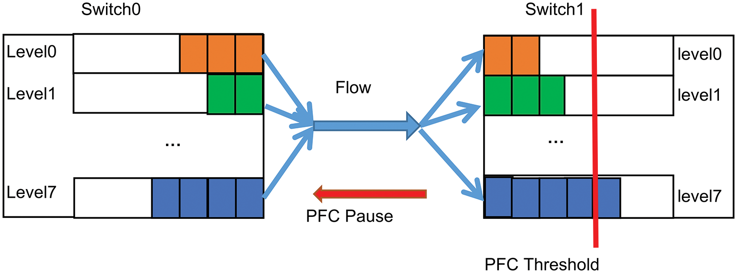
Figure 1: PFC mechanism
DCQCN, TIMELY, Delay is Simple and Effective for Congestion Control in the Datacenter (SWIFT): SWIFT [19] and PCN have been proposed as flow-based congestion control methods since PFC is a coarse-grained congestion control mechanism that operates at the port level rather than at the flow level. Even with these cutting-edge end-to-end congestion control protocols, PFC triggering cannot be avoided entirely. Triggering of PFCs can result in issues such as head-of-line blocking, deadlocks [20,21], PFC storms [1], and even the proliferation of triggering congestion [15].
2.2 Head-of-Line Blocking Issue
According to Fig. 2, Flow1 and Flow2 send packets to the switch’s outgoing queues Egress1 and Egress2, respectively, while they share the same ingress queue Ingress1. The downstream switch sends a PFC pause frame to the upstream switch’s ingress queue Ingress1. This halts the transmission of Flow1 out of that port since the upstream switch’s ingress queue Ingress1 initiates the PFC mechanism. The congested Flow2 prevents the non-congested Flow1 from flowing because it is suspended and not flowing to the outgoing queue Egress2. Head-of-line blocking is the result of this process. To address the head-of-line congestion in PFC, we must implement a flow granularity-based congestion control scheme.
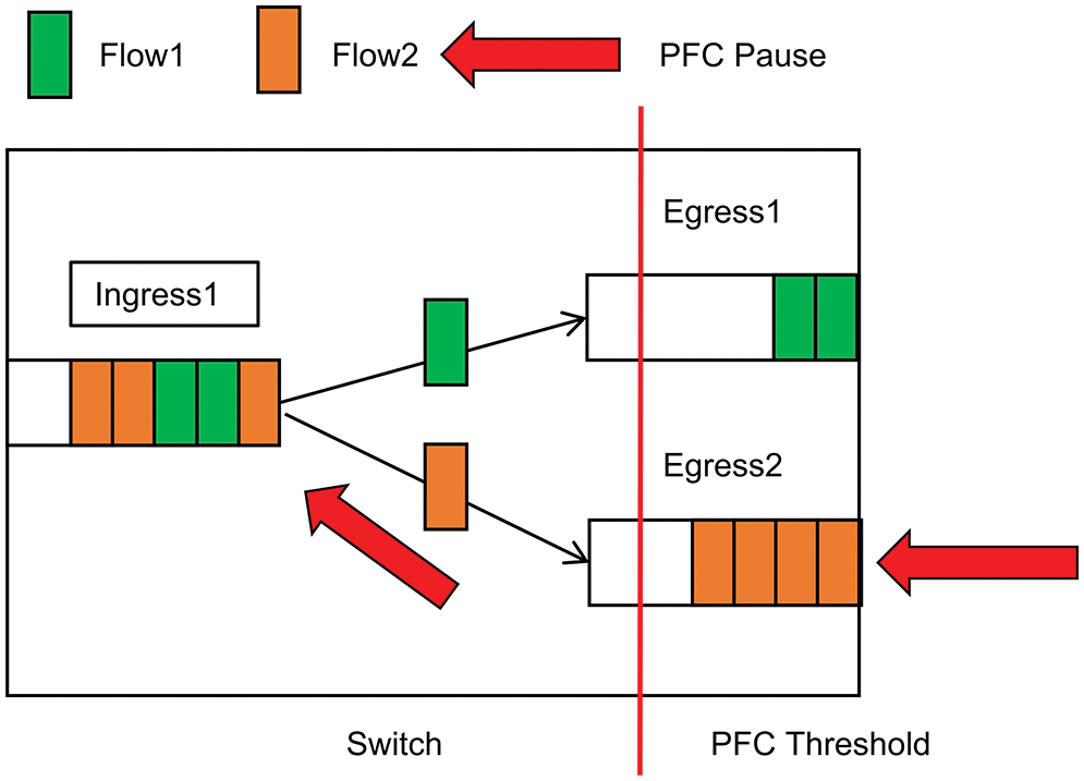
Figure 2: Head-of-line blocking phenomenon
Thresholds detect congestion in traditional TCP, Data Center TCP (DCTCP) [22], and DCQCN schemes. The ECN is designed to carry a single congestion signal, such as a 0 or 1. Google’s Timely and SWIFT algorithms reduce traffic by using RTT as a congestion signal. Additionally, the PCN employs thresholds to identify congestion and the ECN to carry the congestion signal. High Precision Congestion Control (HPCC) differs from them. While ICC does not rely on conventional congestion signals, it can be implemented on existing commercial switches, which is undoubtedly advantageous for congestion control in lossless networks. INT collects congestion information, and queue change rate and link utilization are used to determine congestion.
2.4 Heavy-Tailed and Burstiness of Datacenter Traffic
Recently, data mining, real-time recommendation, large-scale machine learning training, and other new applications have been running in the data center. Compared to traditional Wide Area Networks (WANs), they produce different types of data traffic. Currently, data center network traffic and application requirements are classified as follows:
1) Various applications within the data center generate different data flows with varying transmission performance requirements [23,24]. Application services that produce a lot of short, burst flows of data, such as Web Search and various query services, must meet strict latency requirements. Even though they periodically transmit large volumes of data in the form of long flows, applications such as deep learning online training, data mining, and backup require high network bandwidth.
2) Data flow length is a heavy-tailed distribution [25] in data center networks. A heavy tail is observed in the distribution of data flow lengths in data center networks. Based on a comprehensive study and survey of data center traffic, 90% of data flows in data centers are short flows with fewer than ten milliseconds of data transfer time. Only 10 percent of data flows contain more than 100 KB of data. Despite this, over 80% of the data volume is sent via these lengthy flows. Furthermore, long packets may be sent over the links, resulting in head-of-line blocking.
3) There is a high burstiness [26] in data center network traffic. There is a great deal of erratic network traffic in data centers. High-speed network interface cards often offload the network stack to the hardware to reduce CPU overhead and increase link bandwidth. The traditional network stack can no longer meet ultra-low latency and high bandwidth demands. Due to the high volume of packets sent in a brief period, such a design produces burst traffic, and existing transport and application layer protocols further enhance the burst intensity.
2.5 Lossless Ethernet Implementations
Lossless networks can be implemented in three ways: IB, iWarp [27], and RoCEv2. Ethernet data centers do not typically use IB due to its high cost, need for expensive equipment, and inability to provide ultra-long distance transmissions. It is generally used in high-performance projects. The iWarp protocol is another alternative, but it is less stable and suffers from the same problems as TCP, including high latency and translation vulnerabilities. A hardware network interface card incorporates the entire TCP stack. Compared to IB, RoCEv2 is low-cost, has excellent stability, and can be deployed using standard Ethernet switches. Following extensive research, RoCEv2 was selected as the final choice.
Although many classical congestion control schemes have been proposed, they do not effectively address the queue head-blocking problem of PFC. This is in the case of mixed bursts of long and short flows.
Current congestion control methods, including DCQCN, TIMELY, and PCN, attempt to address the issue of head-line blocking. However, they primarily concentrate on long flows without considering how to avoid PFC and prevent congestion when mixed bursts of long and short flows [28] occur simultaneously. In these schemes, the rate is only adjusted when congestion occurs because the feedback is not accurate and singular enough.
In this paper, we present a typical and ingenious network scenario. In addition to explaining the head-of-line blocking problem in the case of mixed bursts of long and short flows, it can also reveal the basic principle of the core mechanism of lossless Ethernet, enabling us to generalize the result.
As shown in Fig. 3, we chose a typical network topology such as Clos [29] and Fat Tree [30], commonly found in data centers. We then constructed our network topology diagram. In Fig. 3, H0 and H1 are the senders of long flows, whereas H2 to Hn and Hb are the senders of burst short flows. The receivers R0, R1, and R2 are connected to the corresponding switches R0 and R1, while the switches are composed of ports P0 to P6. Typically, each link has a capacity of 100 Gbps and a link delay of five seconds. We also convert the buffer size of the switch to 5 M using the formula.
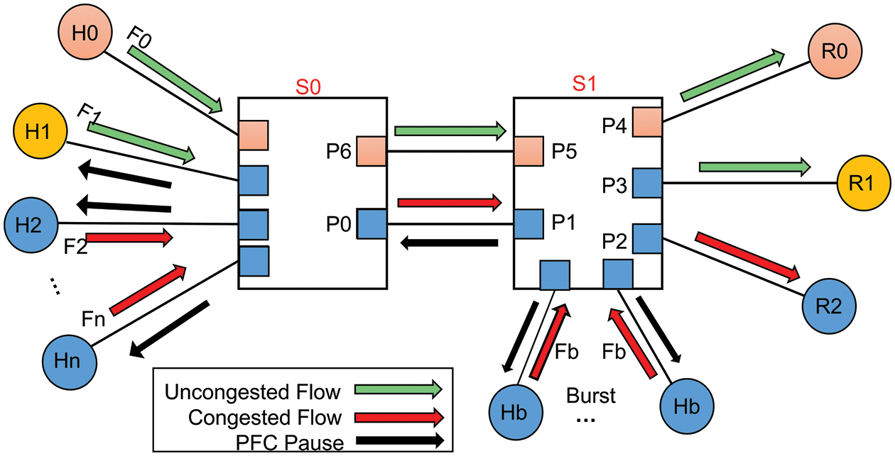
Figure 3: Typical data center network topology
To demonstrate the severity of this problem, we perform NS-3 simulation experiments using the following traffic setups: Server H0 sends a long flow F0 to receiver R0 for comparison with the victim flow F1. A long flow of 100 M is generated by the server H1 and transmitted to the receiver R0. Furthermore, servers H2 to Hn send 60 bursts of 64 Kb short flows to R1. In addition, server Hb delivers 60 short flows to receiver R1. Although F1 and short flows F2 to Fn are transferred to different receivers, R0 and R1, they are all routed through the same ports, P0 and P1. Because burst port P1 will become congested quickly and trigger PFC, the pause message from PFC will be sent hop-by-hop to the upstream switch’s port P0. During this period of congestion, short-flow F1 will not be able to transmit because it is also blocked by the congestion originating from short flows. Therefore, long flow F1 is affected by congestion. Congested flow block non-congested flows, which is known as head-of-line blocking.
We examine several traditional congestion control schemes, including DCQCN, TIMELY, and PCN, and default the parameters in each mechanism paper. To determine how to prevent head-of-queue blocking caused by PFC, we designed NS-3 [31] simulation experiments. Our first step in addressing this issue was to calculate the PFC pause rate and throughput, two metrics that accurately reflect the effects of PFC.
Fig. 4 illustrates the pause rate on this link from S0 to H1. Even before the test, all mechanisms receive minimal pause frames. During the testing phase, long and short flows are sent simultaneously, causing the buffer to fill up immediately. To prevent packet loss, the downstream switch S1 sends pause frames to the upstream switch S0’s P0 port to pause it. Eventually, all servers H1 to Hn will be suspended as the pause message spreads upward in the direction of flow sending. ICC stops sending pause frames at 1.1 milliseconds and has longer PFC pause times than DCQCN, TIMELY, and PCN.
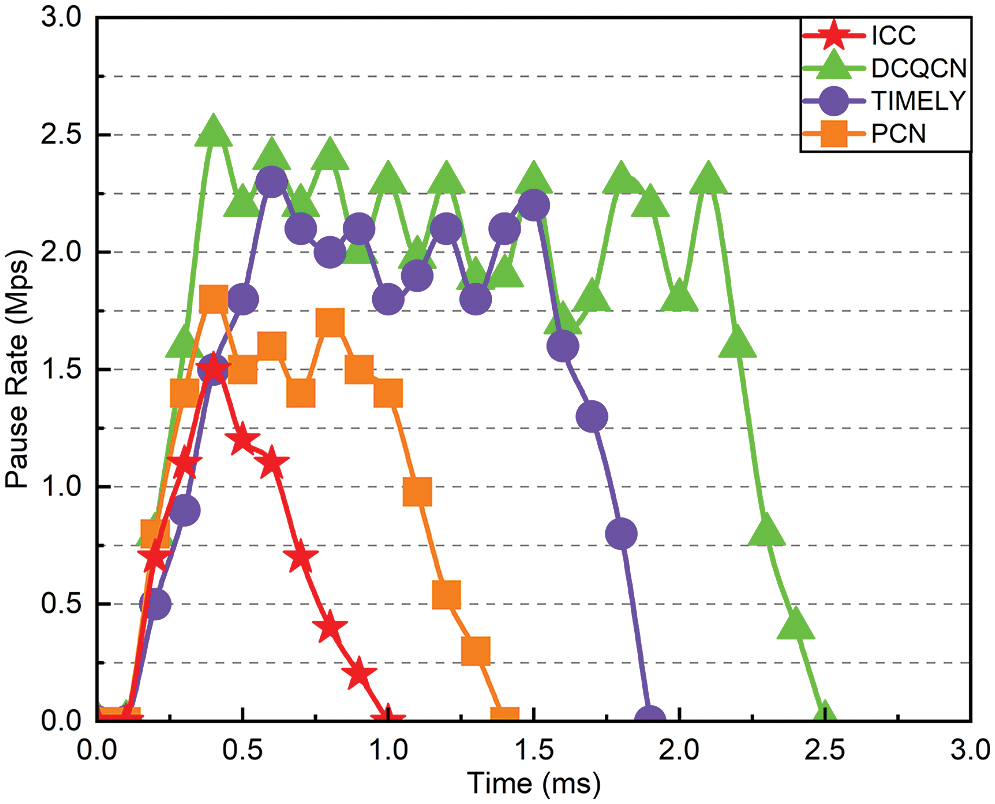
Figure 4: Pause rate of flow F1
Fig. 5 illustrates the entire process of long-flow F1 experiencing a burst. A long-flow F1 almost always transmits packets at 100 Gbps when no burst occurs, but the throughput rate drops to zero immediately when a PFC occurs. As the burst disappears, the throughput gradually returns to normal. Fig. 5 illustrates that DCQCN, TIMELY, and PCN do not recover quickly to their initial values during concurrent bursts lasting 2.5, 1.8, and 1.4 ms, respectively. It takes only 0.4 milliseconds for ICC to return to its initial value.
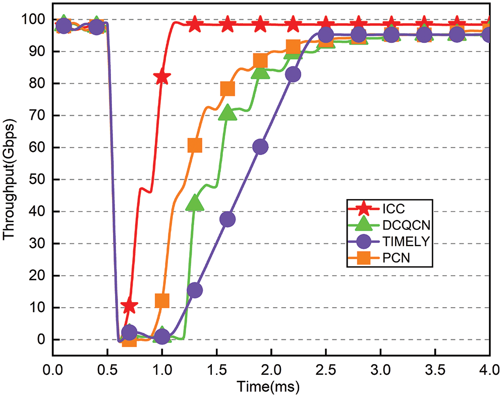
Figure 5: Throughput of F1 under concurrent burst
We first discuss the principle and framework diagram of ICC implementation. Then we describe in detail the particular design of each aspect of ICC, including the module for determining congestion and modifying the transmitter rate.
To address the issues above, we propose ICC, a framework for sender-driven congestion control. The key to its design relies on the switch to obtain detailed load information from INT. It is then used to accurately calculate the sending rate and identify congestion in real-time, resulting in high throughput and low latency without invoking PFC.
Traditional end-to-end congestion control relies on switch queue length or measurement variables such as RTT to identify network congestion. Due to today’s high-speed lossless Ethernet technology, a single coarse-grained congestion signal cannot play a more significant role. It does not follow the current trend of fine-grained network operation to satisfy timely and accurate requirements. We are, therefore, not limited to standard queue lengths or RTTs but instead use the collected congestion information to determine congestion and adjust the rate accordingly. This is due to INT, which can manage rich and accurate congestion signals in real time. INT can control congestion, measure the network, and detect microbursts.
ICC consists of two primary components, the sender and the switch, as shown in Fig. 6. Switches use the INT feature of their switching Application Specific Integrated Circuit (ASIC) to insert metadata into each packet during packet propagation from the sender to the switch. This helps determine whether congestion occurs and monitor packet propagation. In addition to the timestamp queue length, link utilization, link bandwidth capacity, and other statistical load data, these metadata provide information about the switch’s current workload. The switch stores this metadata. The metadata is then included in a passing Acknowledgement (ACK) and sent to the source. To prevent the PFC from being initiated, the sender obtains congestion information from the ACK it receives and adjusts the transmission rate of each flow accordingly. We will then describe in detail the various components of ICC.
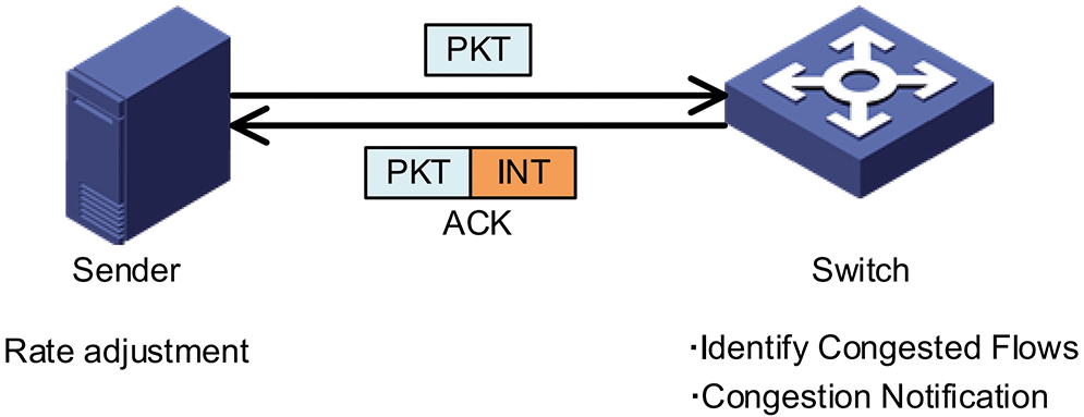
Figure 6: The overview of ICC the framework
4.2 Algorithm for Switch Congestion Identification
The state machine in Fig. 7 is the basis for the switch’s algorithm for determining congestion. After receiving each packet from the upstream switch’s outgoing port, the switch evaluates its current state. If the queue length
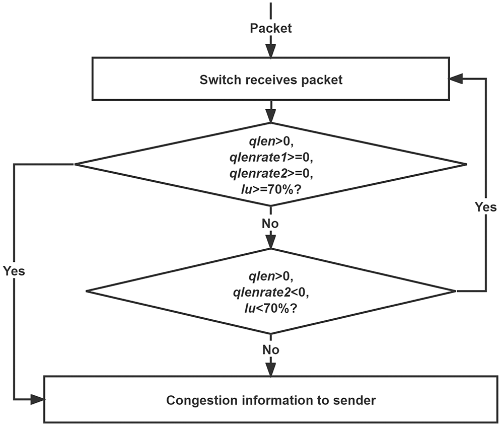
Figure 7: Algorithm for judging congestion at the switch
If the above conditions can’t be met, then we will proceed to the next step of judgment when the queue length
In addition, the switch has an internal timer that sends congestion data to the sender every 15 us, regardless of whether congestion is present. This design has the advantage of allowing the sender to monitor the current network load in real-time. The timer is reset to the current time if congestion is detected, and information about congestion is sent back to the source immediately.
Using some commercial switches, a switch with an internal timer and feedback congestion information can be easily implemented without any problems.
We pass ACK [31] acknowledge packets to transport congestion information rather than creating new packages. Active entry sends congestion information every 15 us. If we also develop new packages to deliver this information, it burdens the already overloaded network, increases the risk of congestion, and decreases network utilization. Our solution is to convey congestion information by passing an ACK, which achieves the same result and reduces network load.
4.3 Algorithm for Adjusting the Rate at the Sender
Algorithm 1 describes the pseudo-code used by the sender to adjust the transmit rate in response to the congestion information contained in the ACK. Table 1 is Algorithm 1, which describes the rate adjustment algorithm. In the following sections, we will discuss the two modules for a rate reduction and rate increase at the transmitter in detail.
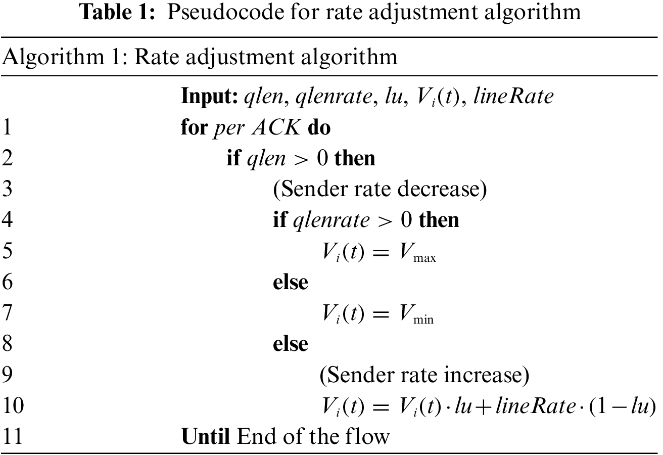
Rate reduction: When the source gets rich congestion information in the ACK, it first jumps to line 2 to determine whether the queue length
We rigorously and theoretically analyze the appropriate range of sending rate values to prevent the PFC from being triggered. The method for adjusting the rate on the sender is shown in Fig. 8.The sending rate of each source host at time t is
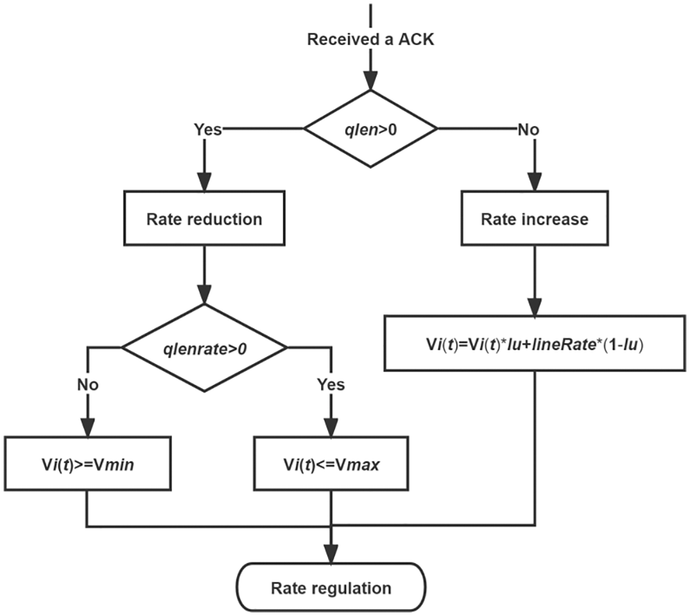
Figure 8: Algorithm for judging congestion at the switch
In the first case, the queue length
The following formula can be used to determine the source’s maximum transmit rate:
The switch’s outgoing port rate equals the NIC’s because the outgoing port has a queue. In order not to trigger the maximum sending rate
The case is when
With the current queue change rate, the expected queue emptying time is given as
The formula for calculating the source’s minimum transmit rate
The source’s minimum send rate,
The send rate at the source is kept in this range during the degradation period, which prevents PFC from occurring and maintains high throughput and low latency, and we reach the conclusion that
Rate increase: Algorithm 1 first decides based on the rule in line 2, and if the queue length
What are the reasons for accepting such a rate increase? By utilizing the link, the sender automatically modifies the transmit rate to be between the current transfer rate and the line rate. The parameters do not need to be manually set, and the link utilization will change with the network load while achieving the desired result.
When the link utilization
Because the source already knows the critical load information of the network, rather than taking the slow growth approach of DCQCN or PCN over multiple iterations, we do not have to use multiple rounds of trial and error to increase the rate. Still, we can increase quickly to the appropriate rate to utilize the effective bandwidth as soon as possible.
To evaluate ICC’s performance under various test scenarios and compare it with DCQCN, TIMELY, and PCN, we used the NS-3 simulation platform to run the tests in Sections 5.1 and 5.2. The congestion detection module and the rate adjustment module are rewritten at the switch’s source, and the ICC algorithm is developed based on the DCQCN algorithm.
5.1 Performance in Burst Scenarios
This section simulates the n:1 incremental scenario frequently occurring in data center networks. This scenario involves sending n flows simultaneously to a single destination host over a PFC-enabled switch, and the performance of ICC is assessed in a burst scenario.
To simulate the incast scenario [15], we use the typical network scenario shown in Fig. 3. Host H1 sends long flow F1, and host H1 receives long flow R0. It is estimated that there are 60 short flow senders on H2 to Hn and 60 short flow senders on Hb. In an incast traffic scenario, H1 transmits packets, while the short flow sends packets and flows to R1. There is a speed of 100 Gbps on each link and a propagation delay of 5 s on each link. All switches are equipped with PFC mechanisms, each with a 5 MB shared buffer.
We will measure the ICC pause rate, the flow completion time, the throughput, and the queue length. Using this burst scenario, we compare DCQCN, TIMELY, and PCN with the default parameters recommended by the relevant literature.
Fig. 9 illustrates the generation rate of PFC pauses. Compared to DCQCN, TIMELY, and PCN, ICC can prevent at least 56%, 63%, and 38% of PFC pauses. ICC’s congestion detection mechanism feeds network information every 15 s as soon as congestion occurs, rather than waiting until congestion exceeds a threshold before triggering control.
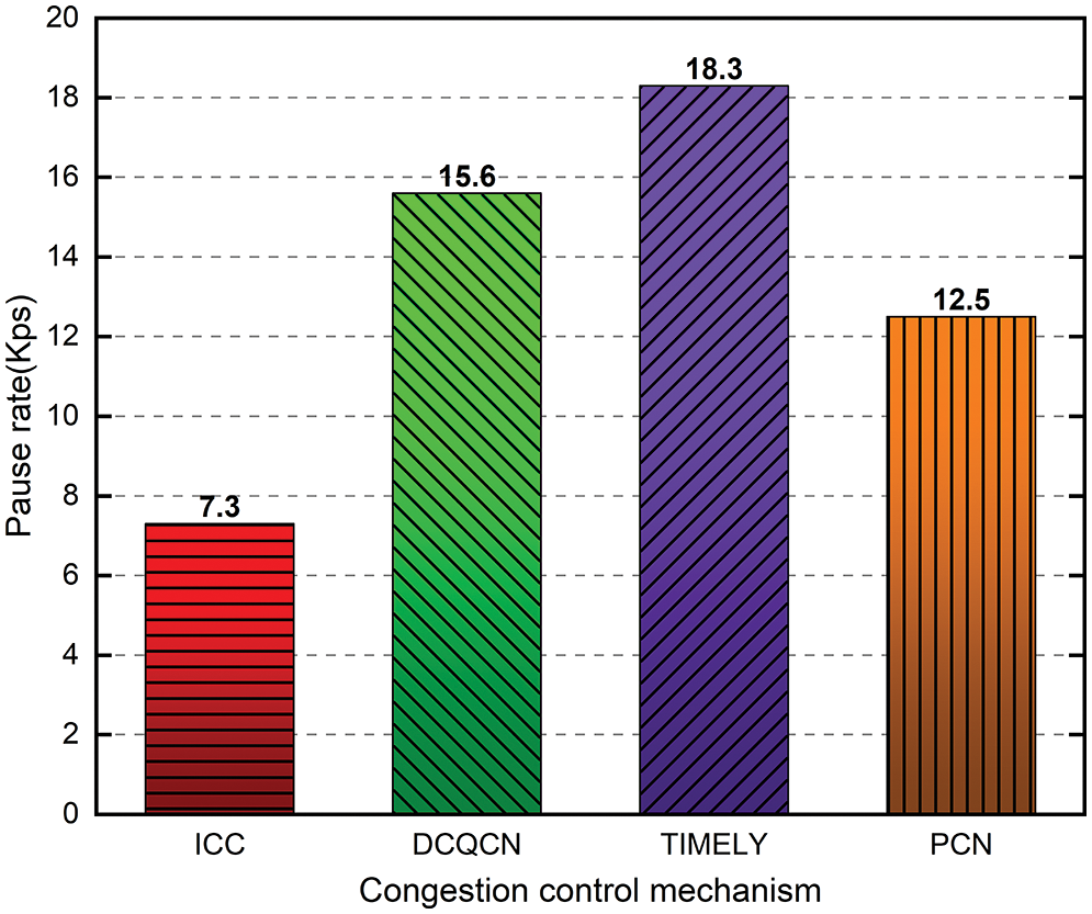
Figure 9: Generating rate of PFC pause
Fig. 5 shows that ICC significantly increases the throughput of F1. All other schemes experience a period during which their throughput is zero after a burst, while ICC quickly resumes its previous throughput. This is partly due to ICC’s ability to restore the sending rate to its original level quickly. ICC outperforms DCQCN, TIMELY, and PCN in this scenario by 51%, 55%, and 38%, respectively.
The average FCT and 99th percentile FCT for different flows are shown in Fig. 10. There is no doubt that ICC also achieves higher levels of FCT than DCQCN, TIMELY, and PCN. Compared to DCQCN, TIMELY, and PCN, ICC’s average FCT for the victim flow H1 is 2.3 times, 2.2 times, and 1.7 times faster, respectively. ICC enhances 99th percentile FCT for concurrent burst flows from H2 to Hn by 3.5×, 3.4×, and 2.7× over DCQCN, TIMELY, and PCN, respectively. As a result of ICC, the queue length of the switch is kept to a minimum. When it reaches a certain threshold, Congestion is marked and controlled by DCQCN. ICC uses a different mechanism for detecting congestion than other schemes.
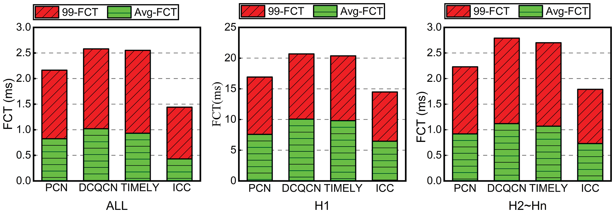
Figure 10: FCT under concurrent burst
Fig. 11 illustrates the change in queue length for switch S0 over time, and ICC can shorten the queue promptly. The ICC queue length is almost zero in the steady state without bursts. In contrast to DCQCN and TIMELY, ICC can abruptly cut the queue length after a burst and maintain it at or near zero. When ICC detects a queue, it feeds back the congestion signal and lowers the sending rate promptly to prevent the queue from accumulating.
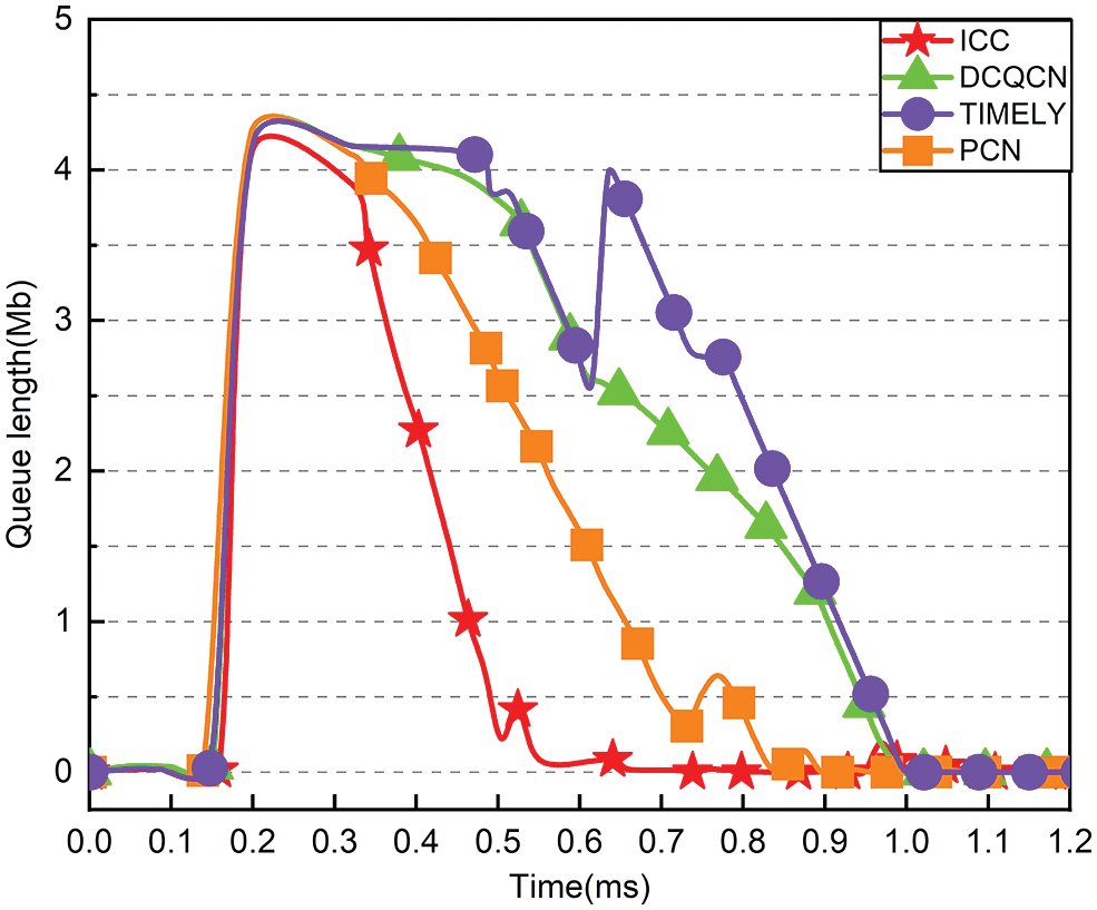
Figure 11: Queue length under different congestion control schemes
5.2 Performance Under Actual Workload
This section aims to evaluate the performance of ICC in real-world scenarios with high workloads. ICC’s pause rate and flow completion time were evaluated under various scenarios and compared to DCQCN, TIMELY, and PCN.
Scenario: As illustrated in Fig. 3, all links have a bandwidth of 100 Gbps, a transmission delay of 5.4 s, and hosts generate a substantial amount of traffic with exponentially distributed arrival times of more than 50,000 flows.
Workload: FB_Hadoop [32,33] simulated real-world traffic to demonstrate ICC’s effectiveness under realistic workloads. This is a typical data center traffic pattern that has a heavy tail. More than 80% of the total number of flows occur in this mode, but less than 10% of the total number of bytes, while long flows greater than 1 M account for 10% of the total number of flows, but almost all of the bytes.
Various traffic patterns are used to stress test the ICC. Additionally, we conducted measurements under the widely used WebSearch [34] traffic to verify the performance under burst scenarios [35] and reach a realistic and general conclusion. Because the results are nearly identical to those obtained with FB_Hadoop, we only display the performance effect graphs for FB_Hadoop traffic scenarios.
Fig. 12 illustrates the ICC of the average flow completion duration for various workloads. We evaluate hosts H1 and H2 to Hn and Hb using an average link density and strength of 20% to 70% of the average flow completion time. ICC significantly reduces the average flow completion time compared to DCQCN, TIMELY, and PCN.
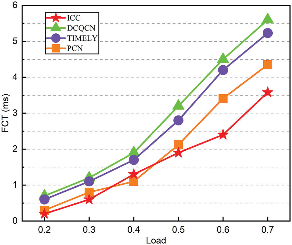
Figure 12: The average FCT with various traffic load
At an average link load of 50%, we analyze the average FCT and 99th percentile FCT for each mechanism. The average FCT is shown at the bottom of Fig. 13, and the 99th percentile FCT is at the top. Based on FCT improvements of 2.45×, 2.83×, and 1.84×, respectively, and avoiding 47%, 56%, and 34% of PFC pauses, ICC is superior to DCQCN, TIMEL Y, and PCN, regardless of host type.
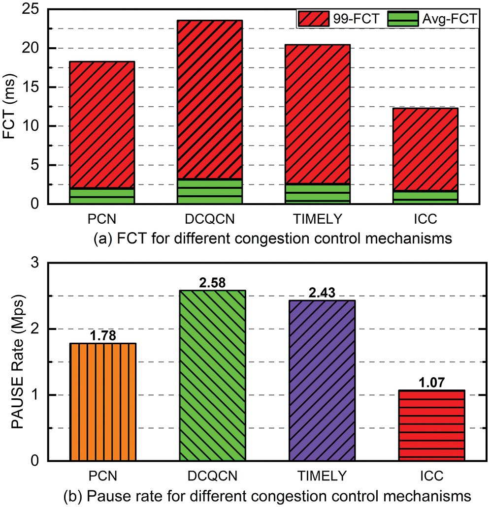
Figure 13: Performance under realistic workloads
To reduce the occurrence of PFC Head-of-Line blocking in data center networks, we proposed ICC, an INT-based congestion control mechanism for lossless Ethernet that prevents PFC triggering through the design of smart switches and senders. The ICC can be implemented on current commodity switches without changing the switch to avoid triggering PFC. The switch judges and forecasts congestion by acquiring rich congestion signals in INT. Simulations and experiments have demonstrated that ICC can significantly reduce the number of PFC pause messages, relieve congestion, and shorten the flow completion time under realistic workloads without affecting throughput.
Funding Statement: This work is supported by the National Natural Science Foundation of China (No. 62102046, 62072249, 62072056). Jin Wang, Yongjun Ren, and Jinbin Hu receive the grant, and the URLs to the sponsors’ websites are https://www.nsfc.gov.cn/. This work is also funded by the National Science Foundation of Hunan Province (No. 2022JJ30618, 2020JJ2029). Jin Wang and Jinbin Hu receive the grant, and the URLs to the sponsors’ websites are http://kjt.hunan.gov.cn/.
Conflicts of Interest: The authors declare they have no conflicts of interest to report regarding the present study.
References
1. Y. L. Li, R. Miao, H. H. Liu, Y. Zhuang, F. Feng et al., “HPCC: High precision congestion control,” Special Interest Group on Data Communication, New York, NY, USA, pp. 44–58, 2019. [Google Scholar]
2. G. Shen, Q. Li, W. Shi, F. Han, Y. Jiang et al., “Poche: A priority-based flow-aware in-network caching scheme in data center networks,” IEEE Transactions on Network and Service Management, vol. 9, no. 2, pp. 103–139, 2022. [Google Scholar]
3. F. Wang, H. P. Yao, Q. Zhang, J. J. Wang, R. Gao et al., “Dynamic distributed multi-path aided load balancing for optical data center networks,” IEEE Transactions on Network and Service Management, vol. 19, no. 2, pp. 991–1005, 2022. [Google Scholar]
4. J. B. Hu, J. W. Huang, W. J. Lv, Y. T. Zhou, J. X. Wang et al., “CAPS: Coding-based adaptive packet spraying to reduce flow completion time in data center,” IEEE/ACM Transactions on Networking, vol. 27, no. 6, pp. 2338–2353, 2019. [Google Scholar]
5. J. B. Hu, J. W. Huang, W. J. Lv, W. H. Li, Z. Y. Li et al., “Adjusting switching granularity of load balancing for heterogeneous datacenter traffic,” IEEE/ACM Transactions on Networking, vol. 29, no. 5, pp. 2367–2384, 2021. [Google Scholar]
6. J. B. Hu, J. W. Huang, Z. Y. Li, Y. J. Li, W. C. Jiang et al., “RPO: Receiver-driven transport protocol using opportunistic transmission in data center,” in Int. Conf. on Network Protocols, Dallas, TX, USA, pp. 1–11, 2021. [Google Scholar]
7. D. Cohen, T. Talpey, A. Kanevsky, U. Cummings, M. Krause et al., “Remote direct memory access over the converged enhanced ethernet fabric: Evaluating the options,” IEEE Symposium on High Performance Interconnects, vol. 17, no. 8, pp. 123–130, 2009. [Google Scholar]
8. J. Wang, C. Y. Jin, Q. Tang, N. N. Xiong and G. Srivastava, “Intelligent ubiquitous network accessibility for wireless-powered MEC in UAV-assisted B5G,” IEEE Transactions on Network Science and Engineering, vol. 8, no. 4, pp. 2801–2813, 2021. [Google Scholar]
9. F. Ruhland, F. Krakowski and M. Schöttner, “Performance analysis and evaluation of java-based InfiniBand solutions,” in Int. Symp. on Parallel and Distributed Computing, Warsaw, Poland, pp. 20–28, 2020. [Google Scholar]
10. W. Mansour, N. Janvier and P. Fajardo, “FPGA implementation of RDMA-based data acquisition system over 100-Gb ethernet,” IEEE Transactions on Nuclear Science, vol. 66, no. 7, pp. 1138–1143, 2019. [Google Scholar]
11. B. -H. Oh, S. Vural, N. Wang and R. Tafazolli, “Priority-based flow control for dynamic and reliable flow management in SDN,” IEEE Transactions on Network and Service Management, vol. 15, no. 4, pp. 1720–1732, 2018. [Google Scholar]
12. M. Scharf and S. Kiesel, “NXG03-5: Head-of-line blocking in TCP and SCTP: Analysis and measurements,” in Global Communications Conf., San Francisco, USA, pp. 1–5, 2006. [Google Scholar]
13. Y. B. Zhu, H. Eran, D. Firestone, C. X. Guo, M. Lipshteyn et al., “Congestion control for large-scale RDMA deployments,” ACM Special Interest Group on Data Communication, New York, NY, USA, pp. 523–536, 2015. [Google Scholar]
14. R. Mittal, V. T. Lam, N. Dukkipati, E. Blem, H. Wassel et al., “TIMELY: RTT-based congestion control for the datacenter,” ACM Special Interest Group on Data Communication, New York, NY, USA, 2015. [Google Scholar]
15. W. X. Cheng, K. Qian, W. C. Jiang, T. Zhang and F. Y. Ren, “Re-architecting congestion management in lossless ethernet,” Networked Systems Design and Implementation, Santa Clara, CA, USA, pp. 19–36, 2020. [Google Scholar]
16. L. Z. Tan, W. Su, W. Zhang, H. L. Shi, J. Y. Miao et al., “A packet loss monitoring system for in-band network telemetry: Detection, localization, diagnosis and recovery,” IEEE Transactions on Network and Service Management, vol. 18, no. 4, pp. 4151–4168, 2021. [Google Scholar]
17. J. Z. Liang, J. Bi, Y. Zhou and C. Zhang, “In-band network function telemetry,” ACM Special Interest Group on Data Communication, New York, NY, USA, pp. 42–44, 2018. [Google Scholar]
18. J. Wang, H. Han, H. Li, S. He, P. Kumar Sharma et al., “Multiple strategies differential privacy on sparse tensor factorization for network traffic analysis in 5G,” IEEE Transactions on Industrial Informatics, vol. 18, no. 3, pp. 1939–1948, 2022. [Google Scholar]
19. G. Kumar, N. Dukkipati, K. Jang, H. M. G. Wassel, X. Wu et al., “Swift: Delay is simple and effective for congestion control in the datacenter,” ACM Special Interest Group on Data Communication, New York, NY, USA, pp. 514–528, 2020. [Google Scholar]
20. M. Alizadeh, A. Greenberg, D. A. Maltz, J. Padhye, P. Patel et al., “Data center tcp (dctcp),” ACM Special Interest Group on Data Communication, New York, NY, USA, pp. 63–74, 2010. [Google Scholar]
21. S. -Y. Wang, Y. -R. Chen, H. -C. Hsieh, R. -S. Lai and Y. -B. Lin, “A flow control scheme based on per hop and per flow in commodity switches for lossless networks,” IEEE Access, vol. 9, no. 2, pp. 156013–156029, 2021. [Google Scholar]
22. S. H. Hu, Y. B. Zhu, P. Cheng, C. X. Guo, K. Tan et al., “Deadlocks in datacenter networks: Why do they form, and how to avoid them,” ACM Special Interest Group on Data Communication, New York, NY, USA, pp. 92–98, 2016. [Google Scholar]
23. D. F. Shan, F. Y. Ren, P. Cheng, R. Shu and C. X. Guo, “Micro-burst in data centers: Observations, analysis, and mitigations,” in Int. Conf. on Network Protocols, Cambridge, UK, pp. 88–98, 2018. [Google Scholar]
24. D. F. Shan, W. C. Jiang and F. Y. Ren, “Absorbing micro-burst traffic by enhancing dynamic threshold policy of data center switches,” in IEEE Int. Conf. on Computer Communications, Hong Kong, China, pp. 118–126, 2015. [Google Scholar]
25. C. Tian, B. Li, L. L. Qin, J. Q. Zheng, J. Yang et al., “P-PFC: Reducing tail latency with predictive PFC in lossless data center networks,” IEEE Transactions on Parallel and Distributed Systems, vol. 31, no. 6, pp. 1447–1459, 2020. [Google Scholar]
26. C. Wilson, H. Ballani, T. Karagiannis and A. Rowtron, “Better never than late: Meeting deadlines in datacenter networks,” ACM Special Interest Group on Data Communication, New York, NY, USA, pp. 50–61, 2011. [Google Scholar]
27. M. J. Rashti, R. E. Grant, A. Afsahi and P. Balaji, “iWARP redefined: Scalable connectionless communication over high-speed Ethernet,” IEEE High Performance Computing, Dona Paula, Goa, India, pp. 1–10, 2010. [Google Scholar]
28. A. R. Curtis, W. Kim and P. Yalagandula, “Mahout: Low-overhead datacenter traffic management using end-host-based elephant detection,” in IEEE Int. Conf. on Computer Communications, Shanghai, China, pp. 1629–1637, 2011. [Google Scholar]
29. Z. F. Qian, K. S. Ho, A. Xu and K. W. Cheung, “A distributed protocol to reduce blocking for short flows in optical flow switching networks,” in Conf. on Optical Internet, Jeju, Korea (Southpp. 1–3, 2010. [Google Scholar]
30. H. Feng, Y. H. Deng, X. Qin and G. Y. Min, “Criso: An incremental scalable and cost-effective network architecture for data centers,” IEEE Transactions on Network and Service Management, vol. 18, no. 2, pp. 2016–2029, 2021. [Google Scholar]
31. S. -M. Chan, M. -H. Xie, H. -S. Chang and C. -Y. Huang, “Design and implementation of a network coding platform based on NetFPGA and ns-3,” in IEEE Conf. on Network Function Virtualization and Software Defined Networks, Heraklion, Greece, pp. 108–109, 2021. [Google Scholar]
32. A. Roy, H. Y. Zeng, J. Bagga, G. Porter and A. C. Snoeren, “Inside the social network’s (datacenter) network,” ACM Special Interest Group on Data Communication, New York, NY, USA, pp. 123–137, 2015. [Google Scholar]
33. M. Noormohammadpour and C. S. Raghavendra, “Datacenter traffic control: Understanding techniques and tradeoffs,” IEEE Communications Surveys & Tutorials, vol. 20, no. 2, pp. 1492–1525, 2018. [Google Scholar]
34. Y. R. Zhang, Y. F. Liu, Q. K. Qing and F. Y. Ren, “Congestion detection in lossless networks,” Special Interest Group on Data Communication, Virtually (Online), vol. 45, pp. 370–383, 2021. [Google Scholar]
35. T. Zhang, Q. Q. Zhang, Y. S. Lei, S. J. Zou, J. Huang et al., “Load balancing with deadline-driven parallel data transmission in data center networks,” IEEE Internet of Things Journal, vol. 127, no. 2, pp. 991–1005, 2022. [Google Scholar]
Cite This Article
 Copyright © 2023 The Author(s). Published by Tech Science Press.
This work is licensed under a Creative Commons Attribution 4.0 International License , which permits unrestricted use, distribution, and reproduction in any medium, provided the original work is properly cited.
 Downloads
 Citation Tools