
 Submit a Paper
 Propose a Special lssue
 Open Access
ARTICLE

Relative-Position Estimation Based on Loosely Coupled UWB–IMU Fusion for Wearable IoT Devices
1 Sejong University, Seoul, 05006, Korea
2 Samsung Advanced Institute of Technology, Suwon, 16678, Korea
* Corresponding Author: Hyung Seok Kim. Email:
Computers, Materials & Continua 2023, 75(1), 1941-1961. https://doi.org/10.32604/cmc.2023.035360
Received 18 August 2022; Accepted 15 November 2022; Issue published 06 February 2023
 View Full Text
 Download PDF
Abstract
Relative positioning is one of the important techniques in collaborative robotics, autonomous vehicles, and virtual/augmented reality (VR/AR) applications. Recently, ultra-wideband (UWB) has been utilized to calculate relative position as it does not require a line of sight compared to a camera to calculate the range between two objects with centimeter-level accuracy. However, the single UWB range measurement cannot provide the relative position and attitude of any device in three dimensions (3D) because of lacking bearing information. In this paper, we have proposed a UWB-IMU fusion-based relative position system to provide accurate relative position and attitude between wearable Internet of Things (IoT) devices in 3D. We introduce a distributed Euler angle antenna orientation which can be equipped with the mobile structure to enable relative positioning. Moving average and min-max removing preprocessing filters are introduced to reduce the standard deviation. The standard multilateration method is modified to calculate the relative position between mobile structures. We combine UWB and IMU measurements in a probabilistic framework that enables users to calculate the relative position between two nodes with less error. We have carried out different experiments to illustrate the advantages of fusing IMU and UWB ranges for relative positioning systems. We have achieved a mean accuracy of 0.31 m for 3D relative positioning in indoor line of sight conditions.Keywords
Establishing the relative positions of objects is critical for various collaborative applications, including robot movement tracking, virtual/augmented reality (VR/AR), line following, and autonomous vehicles. Establishing the relative positioning between two objects is usually dependent on the deployment of fixed or mobile anchors based on Bluetooth [1], Wi-Fi [2], Global Positioning System (GPS) [3], or ultra-wideband (UWB) radio technology [4]. Most of the solutions applied in relative-position systems use range-measurement techniques. The most common range-measurement techniques are two-way ranging (TWR), time of arrival, time difference of arrival (TDOA), and angle of arrival (AOA). These range-measurement techniques use radiofrequency and acoustic signals to calculate the range between the two devices [5]. Range-measurement devices are especially appealing because they are often affordable, lightweight, computationally simple, and may be used in settings in which GPS is unavailable. This minimizes architecture and processing needs, allowing for the deployment of huge swarms of tiny, low-cost tracking devices in indoor or subterranean locations.
There are numerous existing approaches that seek to integrate range measurements into positioning systems. Most techniques for indoor localization have typically assumed the availability of an infrastructure consisting of four or more anchors with defined coordinates [6,7]. In [8], relative positioning was accomplished using a single anchor under the assumption of fixed motion; in other research, measurements of relative positioning have been accomplished using a range-based simultaneous localization and mapping (SLAM) technique. Other techniques use displacement data obtained from optical sensors, including infrared (IR) and visible-light communication (VLC) devices, to calculate the relative positioning of two objects. However, these methods do not provide a precise position, as IR methods suffer from interference from fluorescent light and sunlight [9], and VLC requires an environment with a clear line of sight (LOS) [10]. Moreover, the hardware and maintenance costs of these solutions are very high. Therefore, researchers have commonly opted for a radio-signal-based range-measurement approach for positioning due to the wide availability of inexpensive and lightweight sensors.
Most range-measurement techniques require constant relative movement between an anchor and an agent to acquire their relative positions [11–14]. Many studies have been conducted in robotics examining relative-location measurement using vision or laser-based sensors. These techniques are restricted in their use in complex scenarios due to field-of-view problems, sensor data association, and ambient illumination issues [14]. Other researchers have used radio signal strength (RSS) techniques with wireless devices through a variety of model-based or fingerprint-based solutions to estimate an object’s location. In contrast to the above-mentioned visual-based sensors, RSS may be used even when there is no LOS. However, the accuracy of RSS-based techniques may vary because radio propagation in an indoor environment can be affected by severe multipath and other site-specific characteristics, and fingerprinting methods require the dataset to be updated if the environment changes [15,16].
Recently, researchers have proposed UWB-based positioning systems that can provide very precise range measurements for both LOS and non-LOS (NLOS) environments. UWB-based positioning employs an approach using TWR to determine the range between two objects and can provide positioning precision within a few centimeters, yielding better results than RSS-based location-tracking methods. UWB-based range-measurement devices use two tags to calculate the relative positioning of objects, such as unmanned aerial vehicles (UAVs) [17] and autonomous vehicles [18].
Some researchers have proposed single range measurement methods to enable localization between two devices [19,20]. These single range measurement based methods involve initiating range measurement between a single anchor and a tag device and calculating the relative position using the acquired single range measurement information. However, such methods require continuous relative motion between two objects, and the relative position accuracy can deteriorate due to parallel motion [21]. Other studies have used three tags to calculate relative positions [22,23]. Both strategies retrieve two-dimensional data about the objects’ relative positions. Only a few studies have been conducted examining three-dimensional (3D) relative-positioning schemes using UWB and other complementary measurement units [24,25]. However, these solutions require the UWB anchors to be placed at fixed sites to enable real-time positioning, and massive installation of UWB anchors is costly and complicated.
Some researchers have proposed on-board UWB-based relative-position systems to solve the above-mentioned issue [26,27]. Although their solutions were found to achieve higher accuracy, they only considered mobile machinery in which the objects move slowly, and they did not consider standard-deviation mitigation in the range measurement, which is one of the main sources of error in UWB-based relative-position systems. Moreover, a UWB-based positioning system can only provide relative position information and not any attitude information, which is a very important factor in most collaborative tasks. An inertial navigation system (INS) can provide attitude information and compensate for positioning errors due to an NLOS environment. Inertial measurement units (IMUs) are generally used in INS-based solutions to provide positioning. However, the data from IMU sensors may be inaccurate due to the accumulation of errors; this must be mitigated or reduced by other sources, such as UWB, to enable precise positioning.
Therefore, a robust relative positioning system must be proposed by incorporating the UWB and IMU sensors to enable precise positioning. The range measurement between two objects is the primary means of calculating the relative position between the two devices. The UWB device can be used as a range measurement sensor because it can provide cm level accuracy unlike other devices such as Wi-Fi, Bluetooth, and Zigbee. Moreover, the recently developed UWB devices are cost effective compared to previously developed devices. The available UWB devices use different ranging methods such as TWR, TDOA, and AOA to enable range measurement between two devices. However, it is found that TWR can provide more precise range measurement in a dynamic environment as it can mitigate the clock drift and time synchronization issues found in UWB based range measurement methods. Therefore, TWR range measurements can be used for UWB devices. One of the limitations of the UWB device is the lack of pose estimation and deterioration of range accuracy in NLOS, which can be solved by using an IMU sensor. The IMU sensors can provide information about the displacement of the objects, which can be integrated with UWB devices to reduce the standard deviation of the relative positioning error. Moreover, the IMU sensor can also provide pose estimation, and the pose estimation information from both objects can be integrated to enable relative pose estimation between two objects. Therefore, this study integrates the UWB and IMU devices to propose a relative positioning system for wearable IoT devices. The UWB-based range measurement technique is used to estimate the range between two devices. The estimated range is then filtered using the moving average and min-max filtering methods prior to calculating the 3D relative position between the two devices. UWB antennas are distributed in a squared mobile structure with the Euler angle orientation method. The distributed Euler angle orientation is responsible for acquiring 3D relative position with precise accuracy. The multilateration method is modified according to the structural requirement of the proposed relative positioning system. Moreover, a novel UWB and IMU fusion method is proposed to reduce position error and increase the update rate of the system. The main contributions of this study are as follows:
1. A Distributed Euler antenna orientation is proposed to enable 3D relative positioning using a mobile structure.
2. The original multilateration technique is modified to accommodate the proposed antenna orientation.
3. The standard deviation of the UWB range measurements is mitigated using the moving average filter and min-max sample removal filter. Therefore, accurate range measurement is achieved prior to the relative position calculation.
4. A multi anchor based small mobile structure is designed, which can simultaneously provide relative position and orientation of the mobile nodes without needing any fixed anchor placement in an indoor environment. Moreover, the IoT platform is also utilized to transmit the relative position data to Unity software to provide real time position representation.
5. Real-world experiments demonstrate that the system achieves very good accuracy in an indoor environment, where the proposed system outperforms other available solutions in terms of accuracy for 3D relative position.
The rest of the paper is divided as follows: Section 2 discusses the related literature, preliminaries are discussed in Section 3, Section 4 is dedicated to the materials and methods of the proposed solution, experimental results are analyzed in Section 5, discussion about the proposed solution in contrast to existing solutions is done in Section 6, and finally, a conclusion is drawn in Section 7.
Due to the increasing need for location-aware services, there has been a rise in research examining indoor localization over the past few years. Numerous studies have concentrated on indoor positioning using a static infrastructure. Wireless-network-based infrastructures, for instance, often include many wireless access points to provide full network coverage. Numerous off-the-shelf technologies are capable of providing RSS indicators, which can be used to estimate the position of a mobile node [28,29]. Obtaining a priori information about a structure is impractical in various situations, such as when workers are exploring disaster zones, during collaborative tasks, and for VR/AR agents. Therefore, researchers are now concentrating on relative positioning as opposed to indoor positioning. The authors of [30] described a placement technique for static sensor nodes in a sensor network. During placement, location uncertainty occurs in some nodes [31,32], and this will spread to neighboring nodes, resulting in inaccurate positioning.
To address these issues, a UWB-based relative-positioning scheme can be deployed, which can concurrently perform positioning and transmission with low latency. In comparison to the aforementioned conventional positioning technologies, UWB-based relative-positioning technology is much more flexible to complex scenarios and possesses all of the benefits of collaborative positioning applications. Although UWB is a kind of wireless-based positioning system, its greater temporal resolution allows it to deliver significantly more precise locations than other wireless-based solutions. UWB-based approaches have been extensively employed in transportation in recent years, but in most situations, UWB anchors must be placed beside pathways to determine the exact location of a vehicle [33,34]. However, the cost of placing UWB anchors on a large scale is high, and their installation can be very complex.
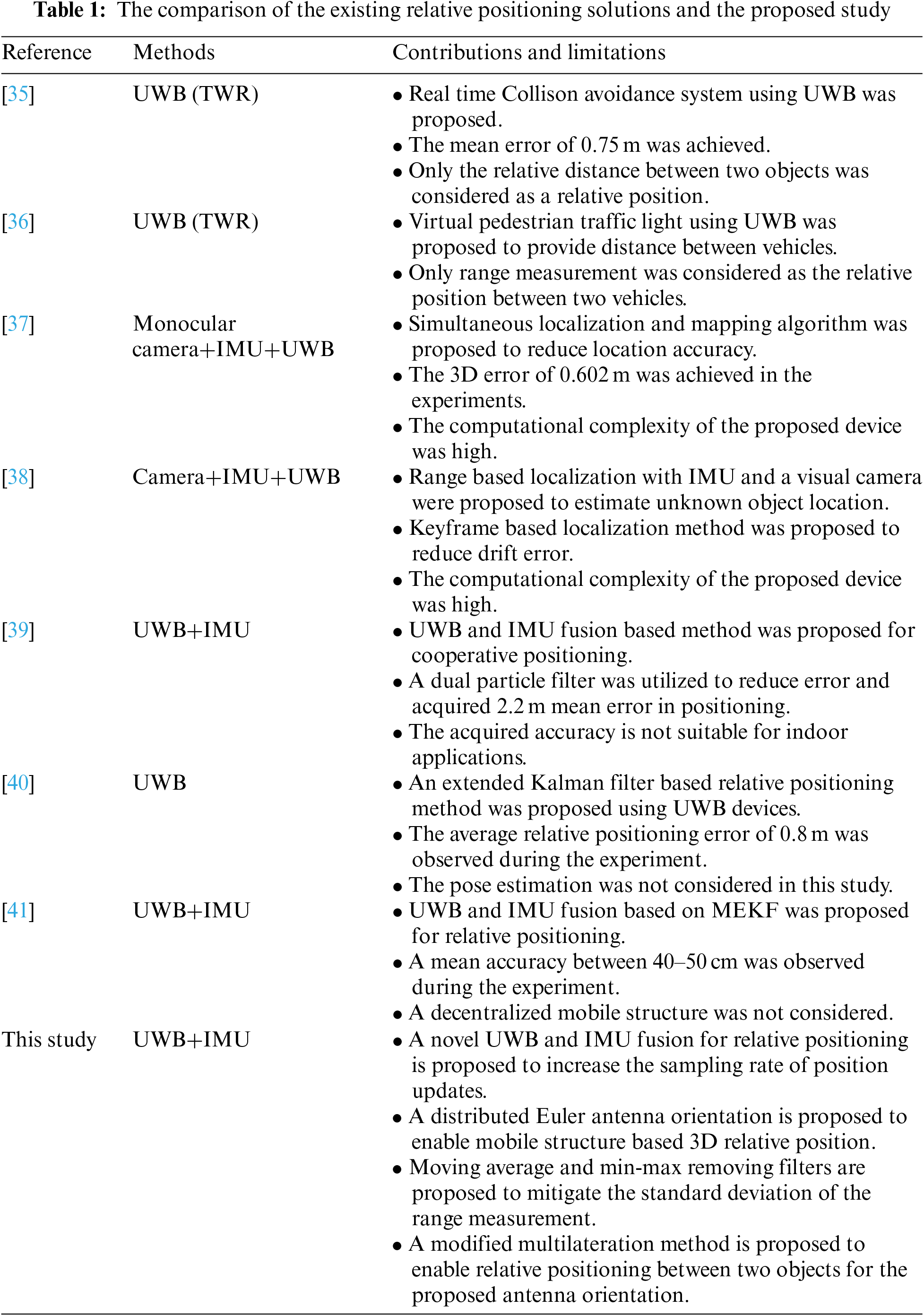
Table 1 shows the comparison between the existing solution and the proposed method. The comparison shows that most of the works only considered relative range measurement as relative positioning. Other works lack precise accuracy, mobile structure, and cost effective solutions. Therefore, it is evident from this literature review that the relative position accuracy for both 2D and 3D applications of these approaches is still not suitable for real-time implementation in scenarios such as VR and collaborative tasks. Moreover, the approaches used by most studies do not provide relative attitude information between two mobile nodes, which is crucial for life-critical collaborative tasks. Therefore, we propose a UWB–IMU fusion-based relative-position system to accurately calculate the relative position between two objects with a small mobile structure. The relative attitude is also calculated using a low-cost on-board IMU sensor.
A schematic of the basic system architecture can be seen in Fig. 1. Multiple UWB anchors are placed in a small mobile structure to accurately estimate other mobile nodes’ relative positions. There are four UWB anchors and one UWB tag on each mobile structure (node); this enables the measurement of a 3D relative position between them.
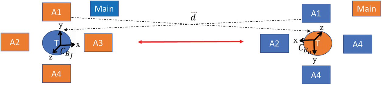
Figure 1: Overall structure of the mobile units (nodes) in the proposed relative-position system. Each node is equipped with four UWB anchors and one UWB tag
The attitude of each mobile structure is defined as
where
where
3.2 UWB Range Measurement Constraints
A UWB-based range measurement in an LOS environment can be defined as:
where the reported distance
The proposed system uses an IoT platform to transfer the data from the remote device to the Unity software. Fig. 2 shows the overall system architecture of the UWB–IMU-based relative-position system. The UWB and IMU sensors collect data and send it to a microcontroller device using the Serial Peripheral Interface and I2C protocols. The Qorvo DWS1000 UWB module and the InvenSense MPU-9250 IMU module were selected, as they are inexpensive and provide high accuracy when compared to other modules available at a similar price. The microcontroller collects the data and performs TWR to determine the distance between two objects. Data processing is also carried out prior to the calculation of the relative position. The STM32-based Nucleo F429ZI microcontroller development board was used as per the instructions of Decawave. Then, the acquired range measurement is sent to a Raspberry Pi development board using the universal asynchronous receiver-transmitter method to calculate the relative position using a fusion of the UWB and IMU sensors. The relative-position data is then sent to the base station via the hypertext transfer protocol (HTTP) and the Unity software as a VR platform to represent the relative position between the two objects in an indoor environment. In this work, a laptop was used as a base station to collect the relative-position data and represent it in the software. The UWB–IMU fusion-based relative-position system can be divided into two parts: a UWB-based relative-position system and a UWB–IMU fusion-based relative-position system. Detailed descriptions of these parts are presented in this section.
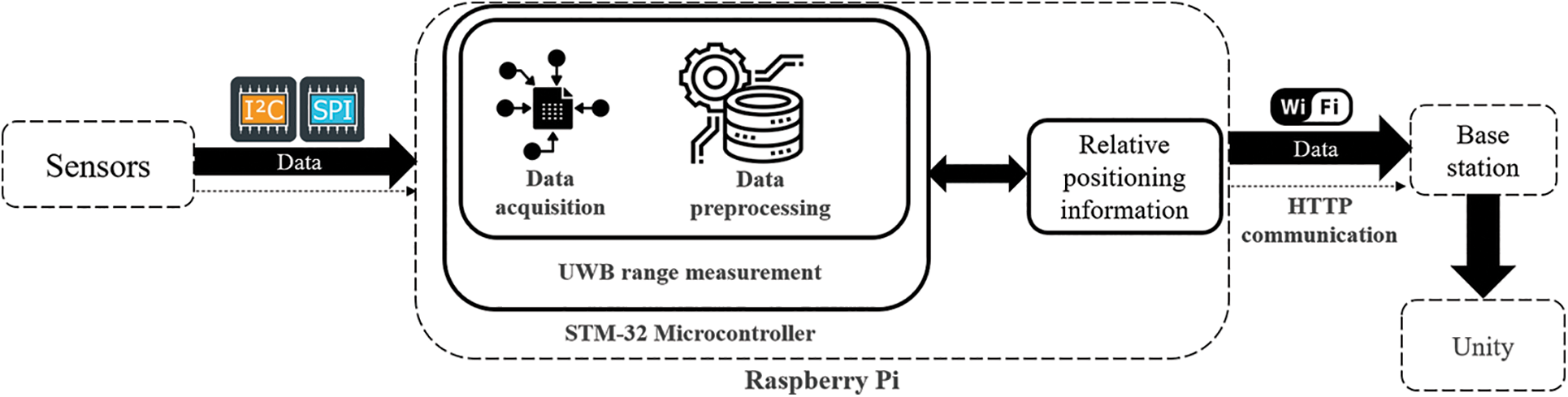
Figure 2: Overall architecture of the UWB–IMU-based relative-position system
Fig. 3 shows the proposed UWB–IMU fusion method that is used to calculate the relative positioning of the two mobile nodes. The range measurement from the UWB devices and the IMU information from the two nodes are fused to perform this calculation. Then, an extended Kalman filter is used to process the calculated relative position, and a filtered relative position is obtained.
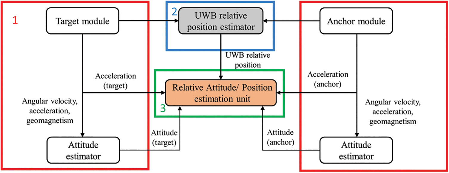
Figure 3: Overall architecture of UWB–IMU fusion-based 3D relative-position system
The IMU can provide displacement information about a device without the need for other devices. However, as noted, IMU measurements suffer from errors that must be minimized before fusing the IMU information with that from the UWB devices. The extended Kalman filter is used to mitigate the Euler angle and gyro-bias errors from the IMU device. The filtered values are then used to calculate the acquired relative position from the UWB system, and the attitude from the IMU module is sent to the relative position and attitude estimation unit to fuse the data. The device’s attitude (ϕ, θ, and ψ) is calculated according to the north-east-down standard.
4.1 UWB Relative-Position System
The proposed method uses UWB-based range measurements from four anchors and one tag to calculate the relative position between two objects. The overall concept of this system is presented in Fig. 4. Range measurements are taken using the four anchors of one node and the single tag of another node. The UWB range-measurement system uses a TWR technique to acquire the range between each anchor and the tag. The acquired range measurements are then sent to data-processing algorithms to filter and stabilize the data; moving average and min-max sample removal filters are used to process the data. The processed data are then used to calculate the relative position of the nodes in 3D. A modified multilateration technique with novel antenna orientation is used to calculate 3D relative position with reasonable accuracy. Although the available positioning algorithms have good accuracy, absolute mitigation of the position error is not possible. A Kalman filter was developed for the proposed method to reduce position error.
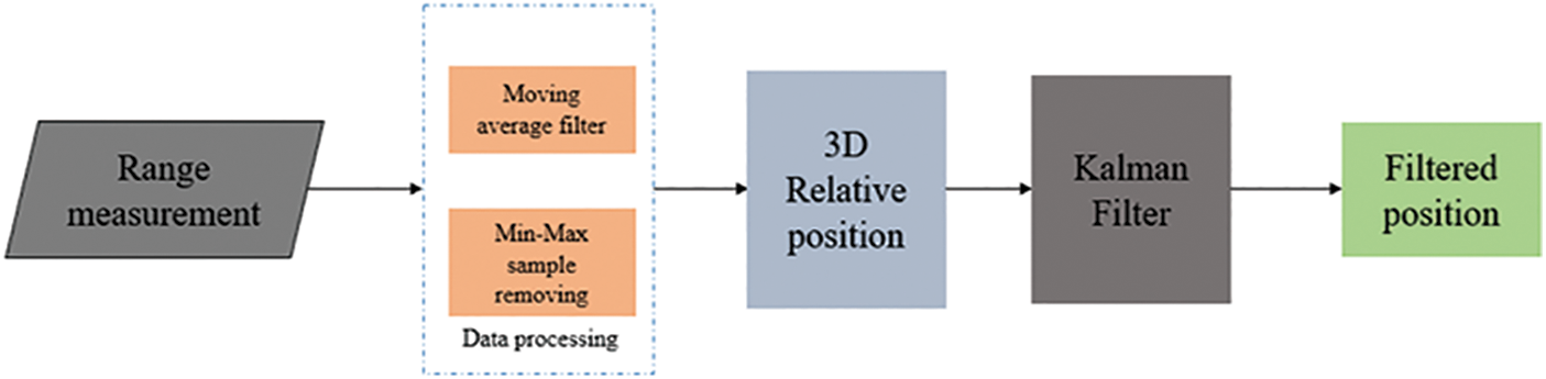
Figure 4: Proposed 3D relative-position measurement using UWB
UWB devices offer many approaches for determining the distance between mobile nodes, including TDOA, TWR, and AOA. In our proposed system, the asymmetric double-sided TWR method is used to calculate the range between two nodes by exchanging four messages [18]. The deployed ranging approach lowers the error due to clock drift on both nodes, and it does not require matching reply delays. Fig. 5 shows a complete range cycle being used to derive the range between two nodes. The tag starts the process and collects all the timestamps with the fourth message to calculate the range. The UWB device’s antenna delay is also calibrated according to the instructions in the Decawave UWB chip user manual. The relevant equations are:
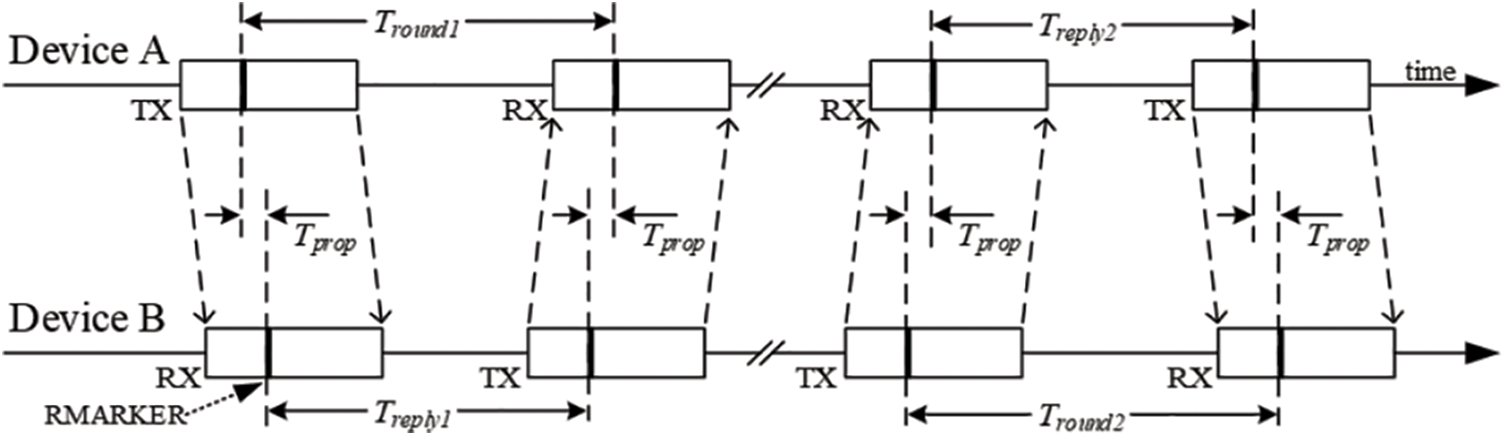
Figure 5: Double-sided TWR used in our proposed system
4.1.2 Min–Max Removal and Moving-Average Filter
As noted, the estimated range measurement from the UWB device is also affected by the standard-deviation problem, which makes positioning very unstable. To mitigate this problem, we used min-max sample removal followed by a moving-average filter. The update rate of the UWB range samples is 30 Hz. Thus, 30 samples are collected in a list to find the maximum and minimum values, and these values are removed from the list prior to it being sent to the moving-average filter.
Moving-average filters are widely used to regulate many types of collected data and signals; they take M input samples at a time and average them to get a single output point. The smoothness of the output increases as the filter length grows, and any sharp modulations in the data become progressively flatter. Initially, 30 samples are taken to smooth the range measurement, but after the min-max sample removal, 28 samples are used to perform the moving-average filter. The moving average (MA) is:
where
4.1.3 UWB-Based Relative Position
Each node has four anchors at a fixed distance, and a tag is placed between them. In UWB-based devices, the antenna orientation affects the positioning performance, and researchers have found that a vertical orientation yields better results than a horizontal orientation [42]. Therefore, we placed the antennas of the four anchors in a vertical orientation, with the antennas of anchors 3 and 4 rotated by 90 degrees. Fig. 6 shows a diagram of this arrangement. The equations required to calculate the relative position using the four anchors are:
where
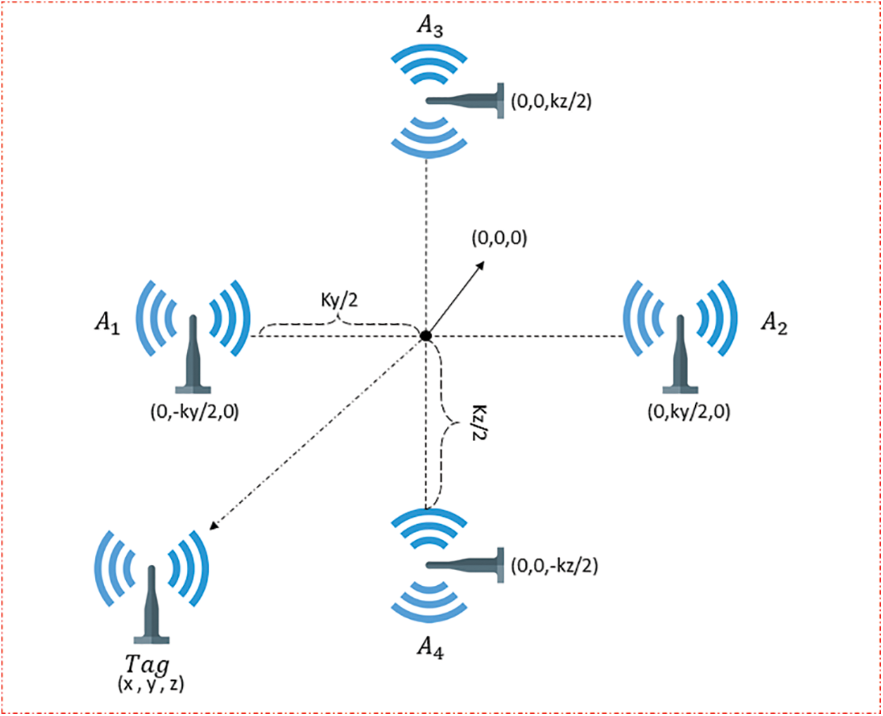
Figure 6: The proposed architecture of the 3D relative-position system using UWB between two devices
4.2 UWB–IMU Fusion Relative-Position System
The relative positions acquired from the UWB measurements and the attitude acquired from the IMU are sent to the relative position and attitude estimation unit to fuse the data using an extended Kalman filter. An extended Kalman filter can be applied to solve nonlinear problems, and it is widely used to estimate the positions and attitudes of objects. The relative position and attitude at time k can be defined as state
where
where
where
The Kalman gain can be calculated using:
The state vector and error covariance are then updated at time k using:
The relative position and attitude are then fused to calculate the final relative position and attitude between two mobile nodes using an extended Kalman filter. The state variable s of the extended filter consists of the relative position from the IMU
State variable,
The state transition matrix of the fusion method is defined as a 3 × 3 matrix, which consists of an identity matrix, zero matrices, and delta time of measurements:
State transition matrix,
Two measurement values are defined to update the position and velocity of the positioning module. The first measurement value is equal to the relative position of the UWB subtracted from the relative position of the IMU. The second measurement value is initiated with the velocity acquired from the IMU sensors.
Measurement,
H is defined as two measurement matrices to calculate the Kalman gain and the update of the measurement from the positioning system. The measurement matrix consists of identity and zero matrices:
Measurement matrix,
The acquired relative position is transferred to a base station, in this case as a laptop, to represent it in the Unity software with avatars. In this study, Wi-Fi was used to transmit the data to the laptop via HTTP. The data was initially stored on a Raspberry Pi before being aggregated and coded into a data frame, including the device ID, 3D position value, and 3D attitude value. The unity VR simulation platform was programmed so that a real-time relative-position demonstration could be shown in the form of an avatar-to-avatar relative positioning.
An extensive experimental study was conducted to evaluate the performance of the proposed UWB–IMU fusion-based relative-position scheme. This section presents experimental results and relevant plots to show the potential of fusing UWB and IMU to provide a smooth relative position.
5.1 Experimental Environment and Setup
All experiments were performed in an indoor environment with two mobile nodes. Decawave DW1000 wireless transceiver chips were used, as these devices are very cheap and can be programmed for development. Researchers conducted extensive experiments on the different UWB devices such as Decawave, BeSpoon, and Ubisense for indoor localization scenarios and found out that the Decawave UWB device performs better than other UWB devices [43]. Therefore, Decawave DW1000 UWB chips were used throughout the study to acquire range measurements. The anchor height was 12 cm, and the width was 65 cm. Moreover, the anchor was vertically placed relative to the tag. The first two anchors were placed vertically at a 90-degree angle, and the last two anchors were rotated to 90 degrees left. InvenSense MPU-9250 nine-axis IMU sensors were used to provide the acceleration, gyroscope, and magnetic information. Both stationary and moving experiments were conducted, and the results were analyzed by calculating the root-mean-square error (RMSE).
5.2 UWB-Based Relative-Position Experiments
For the experiments, two scenarios were considered in which two mobile nodes were placed 5 m apart: in scenario 1, one of the nodes was moved 50 cm in the x direction; in scenario 2, it was moved 50 cm in the y direction. The initial position of the anchor mobile node was fixed at (0, 0, 0), and the target mobile node was initially fixed at (5, 0, 0).
Fig. 7 illustrates the results of scenario 1, in which the mobile node was moved 50 cm in the x direction. The target node’s relative position was acquired with respect to the anchor node. It can be seen from the plot that the mobile node was stable for the initial few seconds prior to moving. It should be noted that the calculated position of the mobile node fluctuated from 0 to 20 cm on the y-axis and −10 to −20 cm on the z-axis, even though there was no actual movement in these directions. The movement of the target node by 50 cm on the x-axis can be seen in the upper plot. However, the new position should correspond to 450 cm, but the mobile node’s calculated relative position varied between 450 and 470 cm. Furthermore, the mobile node’s relative y-axis and z-axis positions continued to vary throughout the experiment.
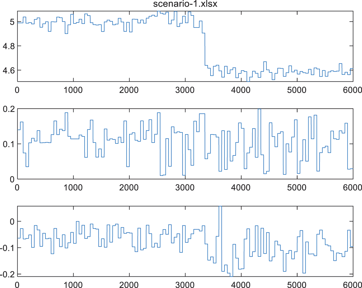
Figure 7: Relative position estimation using the UWB module with a 50 cm movement on the x-axis (from top to bottom, the plots show positions in the x, y, and z directions, respectively)
Table 2 shows the RMSE of the 3D position from the UWB method with scenario 1. The mobile node was stationary for the initial 3000 samples, and the RMSE values were calculated using those samples. The RMSE values were then calculated again using the samples acquired after the node had been moved.
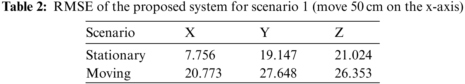
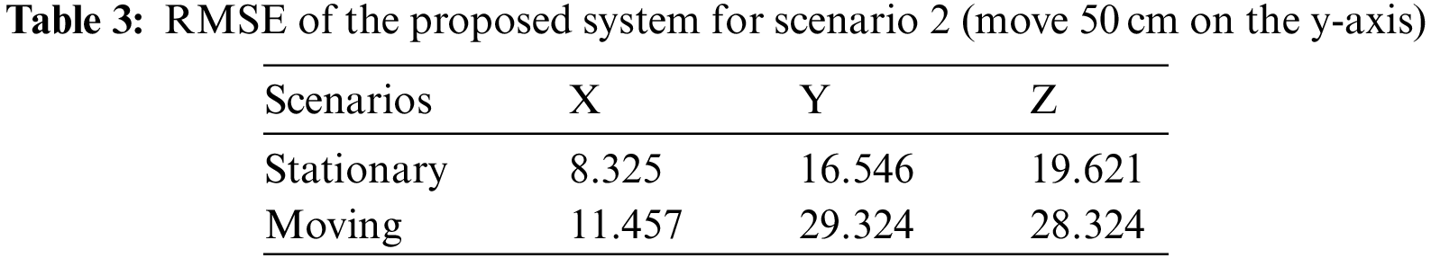
Fig. 8 illustrates the results of scenario 2, in which the mobile node was moved 50 cm in the y direction. The target mobile node’s relative position was again acquired with respect to the anchor node. It can be seen from the plot that both nodes were kept stationary for the initial few seconds prior to moving. Again, it can be noted that the measured x-axis position fluctuated between 490 and 500 cm, and the y-axis position fluctuated between −15 and −35 cm, even though there was no movement. The movement of the target node by 50 cm on the y-axis can be seen in the central plot. However, the new position should correspond to 50 cm, but the mobile node’s calculated relative position varied between 45 and 65 cm. Furthermore, the mobile node’s relative x-axis and z-axis positions again continued to vary throughout the experiment. As with scenario 1, Table 3 shows the RMSE of the 3D position from the UWB method with scenario 2.
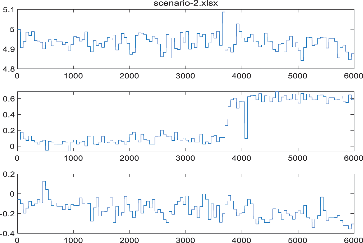
Figure 8: Relative position estimation using the UWB module with a 50 cm movement on the y-axis (from top to bottom, the plots show positions in the x, y, and z directions, respectively)
5.3 UWB–IMU-Based Relative-Position Experiments
This section presents the UWB–IMU fusion experimental results and relevant plots to show the potential of fusing UWB and IMU to provide a smooth relative position. As with the experiments in the previous section, two scenarios were considered. Two mobile nodes were again placed 5 m apart: in scenario 1, one of the nodes was moved 50 cm in the x direction; in scenario 2, it was moved 50 cm in the y direction. Again, the initial position of the anchor mobile node was fixed at (0, 0, 0), and the target mobile node was initially fixed at (5, 0, 0). The UWB position measurement frequency was 1 Hz, and the IMU sensor measurement frequency was 50 Hz.
Fig. 9 shows the experimental results of scenario 1, in which the mobile node was moved 50 cm in the x direction. The target mobile node’s relative position was acquired with respect to the anchor node. Again, there were fluctuations in the positions even though the nodes were stationary. However, it should be noted that the mobile node’s position fluctuated between 5 and 15 cm on the y-axis and between 0 and −5 cm on the z-axis. The movement of the mobile node on the x-axis can be seen in the upper plot. However, it was moved by 50 cm, which should correspond to a position of 450 cm, but the calculated relative position actually varied from 435 to 450 cm. Furthermore, the relative positions on the y and z axes again continued to vary throughout the experiments. As with the previous experiments, Table 4 shows the RMSE values of the UWB–IMU fusion method for scenario 1.
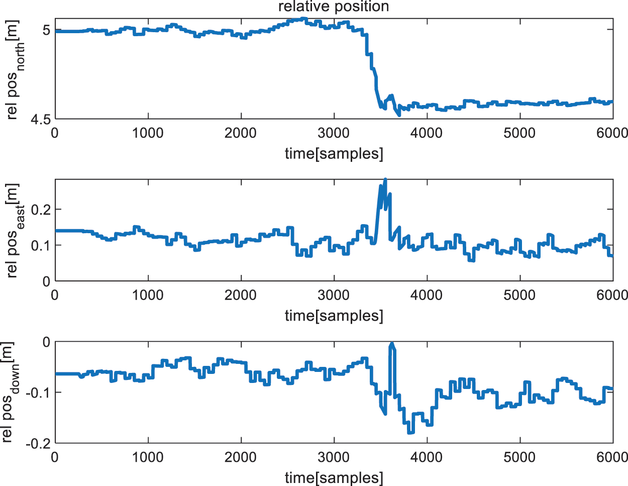
Figure 9: Relative position estimation using the UWB–IMU fusion module with a 50 cm movement on the x-axis (from top to bottom, the plots show positions in the x, y, and z directions, respectively)
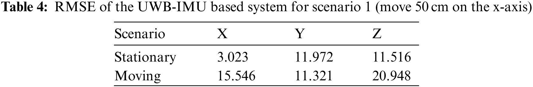
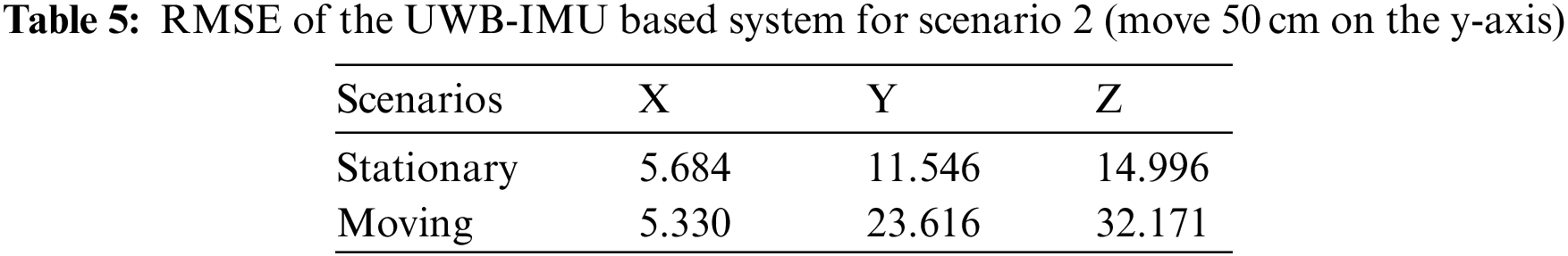
Fig. 10 illustrates the results of scenario 2, in which the mobile node was moved 50 cm in the y direction. Once more, the target mobile node’s relative position was acquired with respect to the anchor node. This time, it can be seen that the x-axis position fluctuated between 490 and 500 cm, and the z-axis position fluctuated between 0 and −15 cm even though there was no movement. The movement of the target node by 50 cm on the y-axis can be seen in the central plot. However, the new position should correspond to 50 cm, but the mobile node’s calculated relative position varied between 50 and 65 cm. Furthermore, the mobile node’s relative x-axis and z-axis positions once more varied throughout the experiment. As with scenario 1, Table 5 shows the RMSE of the 3D position from the UWB–IMU fusion method with scenario 2.
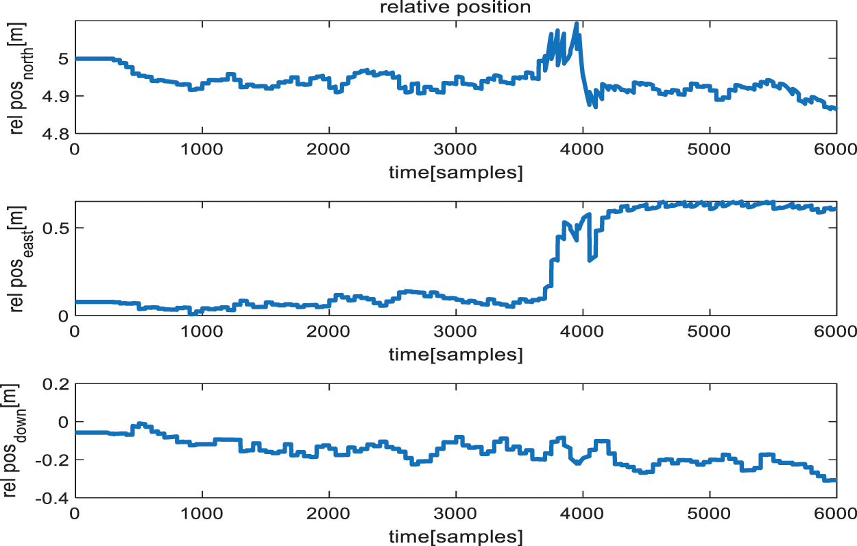
Figure 10: Relative position estimation using the UWB–IMU fusion module with a 50 cm movement on the y-axis (from top to bottom, the plots show positions in the x, y, and z directions, respectively)
5.4 UWB–IMU-Based Relative-Position Trajectory Experiment
The structure of the mobile nodes is shown in Fig. 11. The experiments were conducted indoors, two mobile nodes were placed at a 5 m distance, and the tag node was moved around the anchor node to evaluate the system’s performance in establishing a relative position trajectory. The tag was moved toward the anchor node by 4 m, translated laterally by 2 m, and then returned to its original position by a symmetrical movement. The experimental results are shown in Fig. 12.
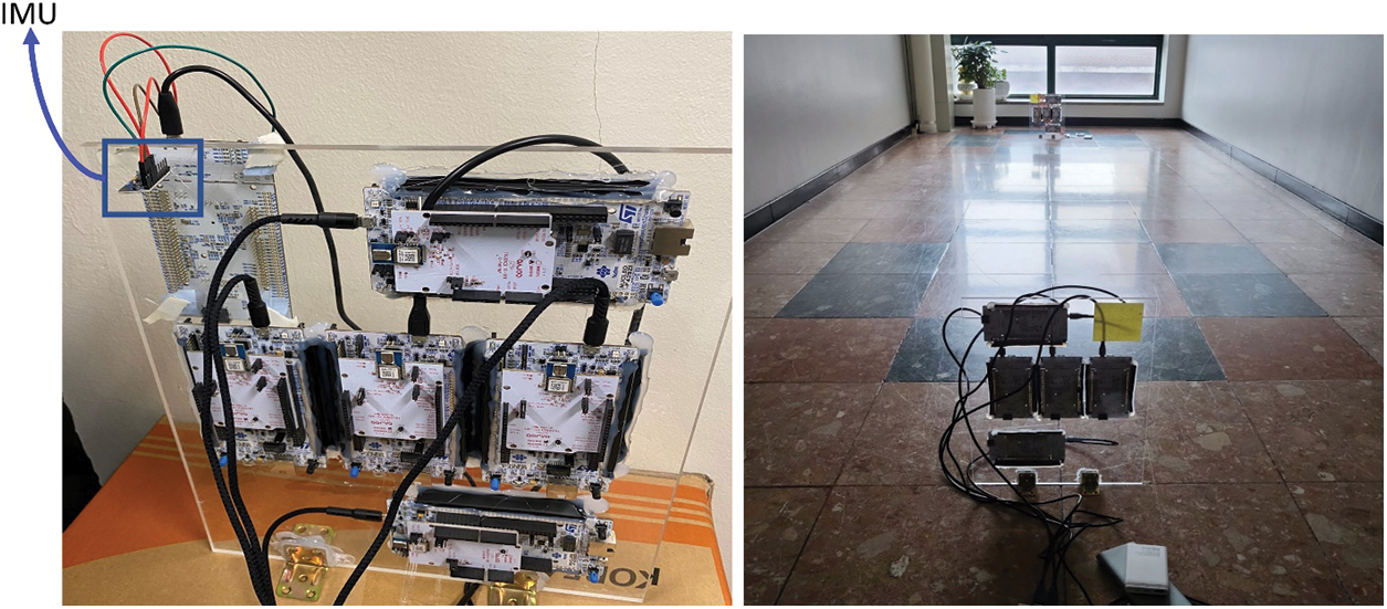
Figure 11: Experimental device and environment used to evaluate the performance of our proposed system. Each mobile node is equipped with four UWB devices and one IMU sensor. The body frame of the mobile node is a plane with four anchor devices placed at a specific distance from the center
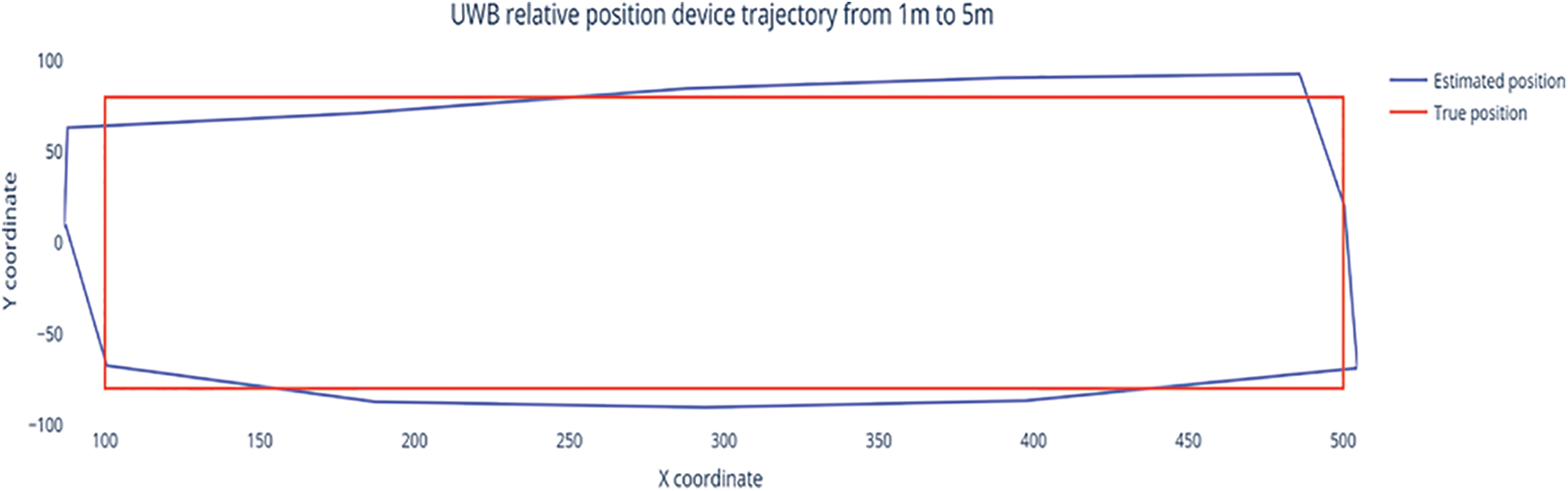
Figure 12: Trajectory from the proposed relative-position system. The blue line represents the position estimated using the proposed system, and the true trajectory is represented by the red line
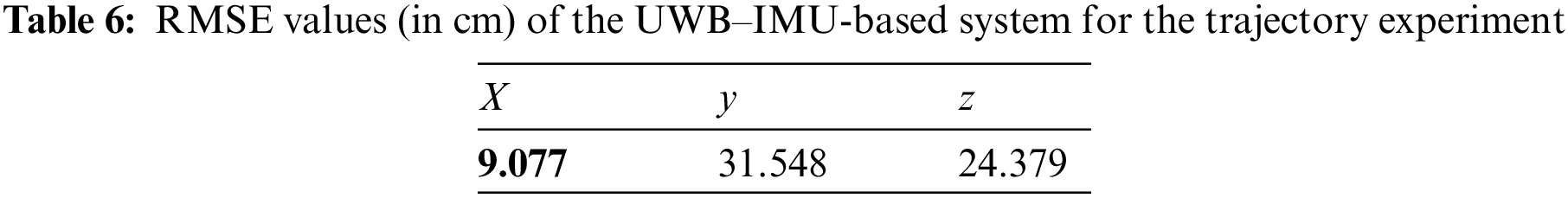
It can be seen that the estimated trajectory matches the ground-truth position very well. The RMSE values were also calculated to evaluate the performance of the relative-position trajectory, and the results are shown in Table 6. It can be seen that the proposed system can achieve centimeter-level accuracy with a long-distance trajectory.
5.5 Relative Position Representation in Unity
VR and AR are promising technologies that can be used for different collaborative tasks, such as telemedicine and teleoperation. The main purpose of this study was to enable relative-position sensing for VR/AR scenarios; the proposed system can calculate two or more avatars’ relative positions. As such, the positionings obtained by the proposed system were represented in Unity to evaluate its real-time usability, and the above-described scenarios were implemented in Unity using the IoT platform. Fig. 13 shows the resulting relative positions of avatars in Unity. The ground truth (GT) locations represent the positions to which the objects move during the experiment; Fig. 13a represents scenario 1, in which the objects move 50 cm in the x direction; Fig. 13b illustrates scenario 2, in which the objects move 50 cm in the y direction. Lastly, Fig. 13c shows a demonstration of the trajectory experiment on the VR platform. It can be seen from Fig. 13 that the data from the proposed system can be applied to a VR platform to represent the relative positions of two avatars, and it can thus be used in collaborative tasks.
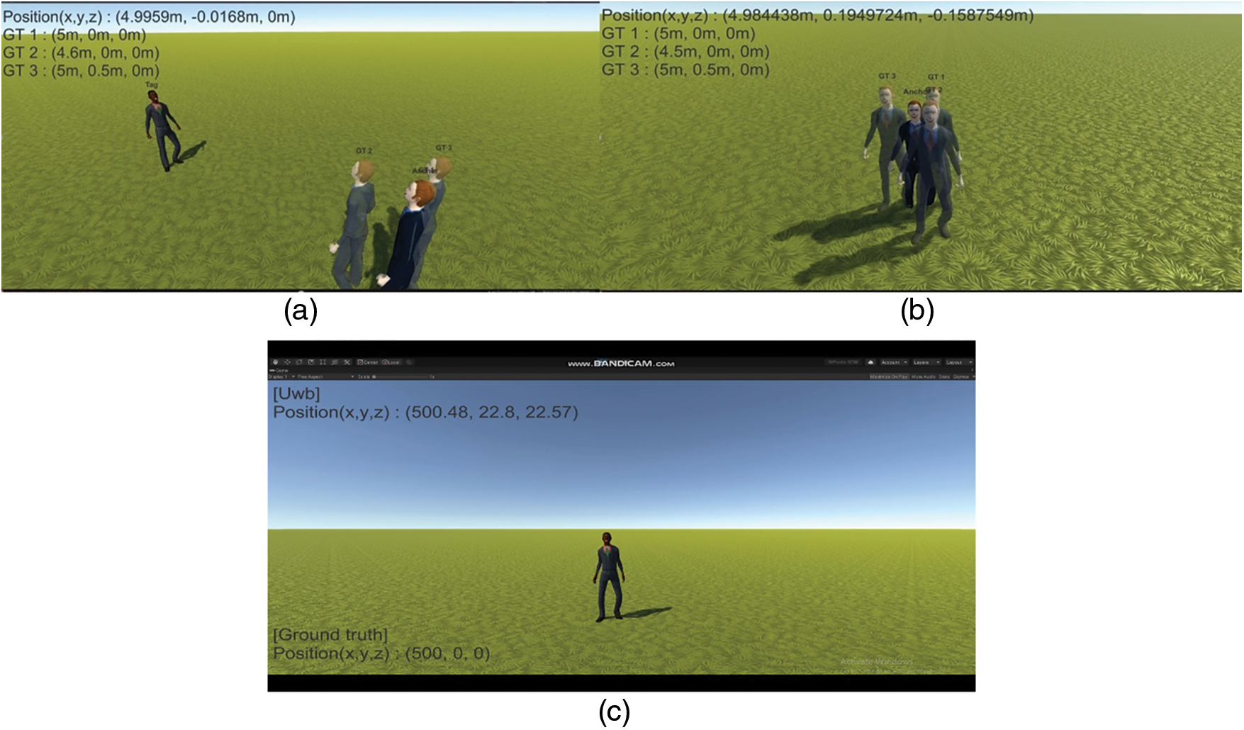
Figure 13: Relative position representation in Unity to demonstrate the proposed relative position for VR/AR: (a) scenario 1, a 50 cm move in the x direction; (b) scenario 2, a 50 cm move in the y direction, (c) trajectory scenario, illustrating a move around another object
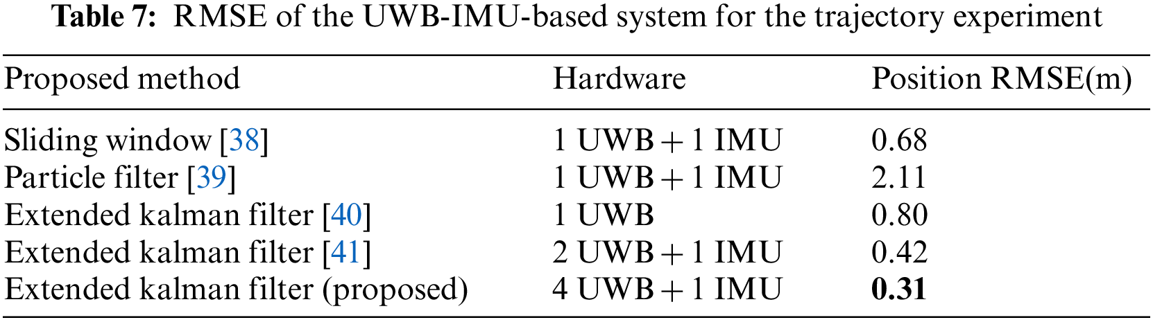
The average RMSE of the proposed system was compared with other relative-position systems in the literature. The purpose of this comparison was to determine the performance of different hardware and algorithm implementations. From Table 7, it can be seen that the performance varies due to the use of different algorithms and devices. As the number of UWB devices is increased, the accuracy is also improved due to the additional range measurements that are provided. The data preprocessing methods also help to improve the accuracy of the relative-position systems by reducing bias and standard deviation. We can see from the comparison that the proposed method has an RMSE of 0.31 m, which is lower than the RMSE values of the other solutions found in the literature. Therefore, it can be said that the proposed relative-position system has high accuracy and can thus be implemented for collaborative tasks such as VR/AR applications.
This paper presents a UWB–IMU fusion-based method for acquiring the relative positions of two mobile nodes. The anchor placement and modified multilateration methods were modified to enable mobile infrastructure-based measurements of relative position. In the present method, measurements from an IMU are fused with UWB measurements to mitigate the error caused by the variance characteristics of the UWB range measurements. The data from the proposed method were also sent to a VR platform to demonstrate its potential for use in VR/AR scenarios. An RMSE relative position accuracy of 0.31 m was achieved in three dimensions. The proposed method yields better results than previous methods; thus, it could be deployed in collaborative robotics tasks and VR/AR applications.
The UWB-IMU fusion-based relative position system is also prone to variations of the position due to the standard deviation of the range measurement. Standard deviation can be mitigated using different filters such as complementary filter, moving average filter, and min-max removal, but these filters decrease the measurement rate of the sensor. The measurement rate of the UWB and IMU devices is very important to enable real-time location-aware services for VR/AR applications. Moreover, more complex scenarios need to be proposed to evaluate the performance of the proposed relative position system. Deep learning methods can be explored to mitigate the range error for both LOS and NLOS environments.
Funding Statement: This work is/was supported by Samsung Advanced Institute of Technology and partly supported by the National Research Foundation of Korea (NRF) grant funded by the Korean government (MSIT) (2022R1F1A1063662).
Conflicts of Interest: The authors declare that they have no conflicts of interest to report regarding the present study.
References
1. G. Bahle, V. Fortes Rey, S. Bian, H. Bello and P. Lukowicz, “Using privacy respecting sound analysis to improve bluetooth based proximity detection for COVID-19 exposure tracing and social distancing,” Sensors, vol. 21, no. 16, pp. 5604, 2021. [Google Scholar]
2. Y. Wang, L. Guo, Z. Lu, X. Wen, S. Zhou et al., “From point to space: 3D moving human pose estimation using commodity WiFi,” IEEE Communications Letters, vol. 25, no. 7, pp. 2235–2239, 2021. [Google Scholar]
3. A. Mohanty, A. Wu, S. Bhamidipati and G. Gao, “Precise relative positioning via tight-coupling of GPS carrier phase and multiple UWBs,” IEEE Robotics and Automation Letters, vol. 7, no. 2, pp. 5757–5762, 2022. [Google Scholar]
4. M. Wang, X. Chen, B. Jin, P. Lv, W. Wang et al., “A novel V2V cooperative collision warning system using UWB/DR for intelligent vehicles,” Sensors, vol. 21, no. 10, pp. 3485, 2021. [Google Scholar]
5. P. Pascacio, S. Casteleyn, J. Torres-Sospedra, E. S. Lohan and J. Nurmi, “Collaborative indoor positioning systems: A systematic review,” Sensors, vol. 21, no. 3, pp. 1002, 2021. [Google Scholar]
6. V. Mai, M. Kamel, M. Krebs, A. Schaffner, D. Meier et al., “Local positioning system using UWB range measurements for an unmanned blimp,” IEEE Robotics and Automation Letters, vol. 3, no. 4, pp. 2971–2978, 2018. [Google Scholar]
7. J. Cano, S. Chidami and J. L. Ny, “A kalman filter-based algorithm for simultaneous time synchronization and localization in UWB networks,” in Proc. IEEE Intl. Conf. Robot. Automat., Montreal, QC, Canada, pp. 1431–1437, 2019. [Google Scholar]
8. Y. Cao, C. Yang, R. Li, A. Knoll and G. Beltrame, “Accurate position tracking with a single UWB anchor,” in Proc. Int. Conf. Robot. Automat., Paris, France, pp. 2344–2350, 2020. [Google Scholar]
9. H. Obeidat, W. Shuaieb, O. Obeidat and R. Abd-Alhameed, “A review of indoor localization techniques and wireless technologies,” Wireless Personal Communications, vol. 119, no. 1, pp. 289–327, 2021. [Google Scholar]
10. M. A. Dawood, S. S. Saleh, E. -S. A. El-Badawy and M. H. Aly, “A comparative analysis of localization algorithms for visible light communication,” Optical and Quantum Electronics, vol. 53, no. 2, pp. 1–25, 2021. [Google Scholar]
11. K. Mannay, J. Ureña, Á. Hernández, J. M. Villadangos, M. Machhout et al., “Evaluation of multi-sensor fusion methods for ultrasonic indoor positioning,” Applied Sciences, vol. 11, no. 15, pp. 6805, 2021. [Google Scholar]
12. T. M. Nguyen, Z. Qiu, T. H. Nguyen, M. Cao and L. Xie, “Distance-based cooperative relative localization for leaderfollowing control of mavs,” IEEE Robotics and Automation Letters, vol. 4, no. 4, pp. 3641–3648, 2019. [Google Scholar]
13. S. van der Helm, M. Coppola, K. N. McGuire and G. C. de Croon, “On-board range-based relative localization for micro air vehicles in indoor leader–follower flight,” Autonomous Robots, vol. 44, no. 3–4, pp. 415–441, 2019. [Google Scholar]
14. S. Zheng, Z. Li, Y. Yin, Y. Liu, H. Zhang et al., “Multi-robot relative positioning and orientation system based on UWB range and graph optimization,” Measurement, vol. 195, pp. 111068, 2022. [Google Scholar]
15. F. Liu, J. Liu, Y. Yin, W. Wang, D. Hu et al., “Survey on wifi-based indoor positioning techniques,” IET Communications, vol. 14, no. 9, pp. 1372–1383, 2020. [Google Scholar]
16. S. Shang and L. Wang, “Overview of WIFI fingerprinting-based indoor positioning,” IET Communications, vol. 16, no. 7, pp. 725–733, 2022. [Google Scholar]
17. W. Shule, C. M. Almansa, J. P. Queralta, Z. Zou and T. Westerlund, “UWB-Based localization for multi-UAV systems and collaborative heterogeneous multi-robot systems,” Procedia Computer Science, vol. 175, pp. 357–364, 2020. [Google Scholar]
18. J. San Martín, A. Cortés, L. Zamora-Cadenas and B. J. Svensson, “Precise positioning of autonomous vehicles combining UWB ranging estimations with on-board sensors,” Electronics, vol. 9, no. 8, pp. 1238, 2020. [Google Scholar]
19. T. H. Nguyen, T. -M. Nguyen and L. Xie, “Range-focused fusion of camera-IMU-UWB for accurate and drift-reduced localization,” IEEE Robotics and Automation Letters, vol. 6, no. 2, pp. 1678–1685, 2021. [Google Scholar]
20. A. Papalia, N. Thumma and J. Leonard, “Prioritized planning for cooperative range-only localization in multi-robot networks,” in Proc. 2022 Int. Conf. on Robotics and Automation (ICRA), Philadelphia, PA, USA, pp. 10753–10759, 2022. [Google Scholar]
21. K. Long, “Single UWB anchor aided PDR heading and step length correcting indoor localization system,” IEEE Access, vol. 9, pp. 11511–11522, 2021. [Google Scholar]
22. M. Wang, X. Chen, P. Lv, B. Jin, W. Wang et al., “UWB based relative planar localization with enhanced precision for intelligent vehicles,” Actuators, vol. 10, no. 7, pp. 144, 2021. [Google Scholar]
23. S. Guler, M. Abdelkader and J. S. Shamma, “Infrastructure-free multi-robot localization with ultrawideband sensors,” in Proc. 2019 American Control Conf. (ACC), Philadelphia, PA, USA, pp. 13–18, 2019. [Google Scholar]
24. D. Shi, H. Mi, E. G. Collins and J. Wu, “An indoor low-cost and high-accuracy localization approach for agvs,” IEEE Access, vol. 8, pp. 50085–50090, 2020. [Google Scholar]
25. W. W. Xue and P. Jiang, “The research on navigation technology of dead reckoning based on UWB localization,” in Proc. 2018 Eighth Int. Conf. on Instrumentation & Measurement, Computer, Communication and Control (IMCCC), Harbin, China, pp. 339–343, 2018. [Google Scholar]
26. S. Monica and G. Ferrari, “Low-complexity UWB-based collision avoidance system for automated guided vehicles,” ICT Express, vol. 2, no. 2, pp. 53–56, 2016. [Google Scholar]
27. E. J. Theussl, D. Ninevski and P. O’Leary, “Measurement of relative position and orientation using UWB,” in Proc. 2019 IEEE Int. Instrumentation and Measurement Technology Conf. (I2MTC), Auckland, New Zealand, pp. 1–6, 2019. [Google Scholar]
28. D. Ko, M. Kim, K. Son and D. Han, “Passive fingerprinting reinforced by active radiomap for WLAN indoor positioning system,” IEEE Sensors Journal, vol. 22, no. 6, pp. 5238–5247, 2022. [Google Scholar]
29. B. H. Pinto, H. A. de Oliveira and E. J. Souto, “Factor optimization for the design of indoor positioning systems using a probability-based algorithm,” Journal of Sensor and Actuator Networks, vol. 10, no. 1, pp. 16, 2021. [Google Scholar]
30. W. Liu, X. Luo, G. Wei and H. Liu, “Node localization algorithm for wireless sensor networks based on static anchor node location selection strategy,” Computer Communications, vol. 192, pp. 289–298, 2022. [Google Scholar]
31. W. Li, B. Jelfs, A. Kealy, X. Wang and B. Moran, “Cooperative localization using distance measurements for mobile nodes,” Sensors, vol. 21, no. 4, pp. 1507, 2021. [Google Scholar]
32. G. Shenkai, C. Li, W. Jing and L. Xianglong, “An improved approach for iterative nodes localization by using artificial bee colony,” in Proc. 2021 Int. Conf. on Neural Networks, Information and Communication Engineering, Qingdao, China, pp. 442–450, 2021. [Google Scholar]
33. W. Xue and P. Jiang, “The research on navigation technology of dead reckoning based on UWB localization,” in Proc. IMCCC, Harbin, China, pp. 339–343, 2018. [Google Scholar]
34. W. Xue and P. Jiang, “The research on navigation technology of dead reckoning based on UWB localization,” in Proc. IMCCC, Harbin, China, pp. 339–343, 2018. [Google Scholar]
35. M. Pittokopiti and R. Grammenos, “Infrastructureless UWB based collision avoidance system for the safety of construction workers,” in Proc. ICT, Hanoi, Vietnam, pp. 490–495, 2019. [Google Scholar]
36. R. Zhang, L. Song, A. Jaiprakash, T. Talty, A. Alanzai et al., “Using ultrawideband technology in vehicles for infrastructure-free localization,” in Proc. WF-IoT, Limerick, Ireland, pp. 122–127, 2019. [Google Scholar]
37. Y. Cao and G. Beltrame, “Vir-SLAM: Visual, inertial, and ranging slam for single and multi-robot systems,” Autonomous Robots, vol. 45, no. 6, pp. 905–917, 2021. [Google Scholar]
38. K. Guo, Z. Qiu, W. Meng, L. Xie and R. Teo, “Ultra-wideband based cooperative relative localization algorithm and experiments for multiple unmanned aerial vehicles in GPS denied environments,” International Journal of Micro Air Vehicles, vol. 9, no. 3, pp. 169–186, 2017. [Google Scholar]
39. R. Liu, C. Yuen, T. Do, D. Jiao, X. Liu et al., “Cooperative relative positioning of mobile users by fusing IMU inertial and UWB ranging information,” in Proc. ICRA, Singapore, pp. 5623–5629, 2017. [Google Scholar]
40. K. Guo, Z. Qiu, W. Meng, L. Xie and R. Teo, “Ultra-wideband based cooperative relative localization algorithm and experiments for multiple unmanned aerial vehicles in GPS denied environments,” International Journal of Micro Air Vehicles, vol. 9, no. 3, pp. 169–186, 2017. [Google Scholar]
41. M. Shalaby, C. C. Cossette, J. R. Forbes and J. Le Ny, “Relative position estimation in multi-agent systems using attitude-coupled range measurements,” IEEE Robotics and Automation Letters, vol. 6, no. 3, pp. 4955–4961, 2021. [Google Scholar]
42. P. Chansamood, S. Wisadsud, K. Maneerat, T. Sanpechuda, K. Chinda et al., “Effects of antenna orientation in ultra wideband indoor positioning system,” in Proc. 2019 16th Int. Conf. on Electrical Engineering/Electronics, Computer, Telecommunications and Information Technology (ECTI-CON), Pattaya, Thailand, pp. 397–400, 2019. [Google Scholar]
43. A. R. Jiménez Ruiz and F. Seco Granja, “Comparing ubisense, BeSpoon, and DecaWave UWB location systems: Indoor performance analysis,” IEEE Transactions on Instrumentation and Measurement, vol. 66, no. 8, pp. 2106–2117, 2017. [Google Scholar]
Cite This Article
 Copyright © 2023 The Author(s). Published by Tech Science Press.
This work is licensed under a Creative Commons Attribution 4.0 International License , which permits unrestricted use, distribution, and reproduction in any medium, provided the original work is properly cited.
 Downloads
 Citation Tools