
 Submit a Paper
 Propose a Special lssue
 Open Access
ARTICLE

Relational Logging Design Pattern
1 Ankara University, Ankara, 06560, Turkey
2 Kafkas University, Kars, 36000, Turkey
* Corresponding Author: Savas Takan. Email:
Computers, Materials & Continua 2023, 75(1), 51-65. https://doi.org/10.32604/cmc.2023.035282
Received 15 August 2022; Accepted 26 October 2022; Issue published 06 February 2023
 View Full Text
 Download PDF
Abstract
Observability and traceability of developed software are crucial to its success in software engineering. Observability is the ability to comprehend a system’s internal state from the outside. Monitoring is used to determine what causes system problems and why. Logs are among the most critical technology to guarantee observability and traceability. Logs are frequently used to investigate software events. In current log technologies, software events are processed independently of each other. Consequently, current logging technologies do not reveal relationships. However, system events do not occur independently of one another. With this perspective, our research has produced a new log design pattern that displays the relationships between events. In the design we have developed, the hash mechanism of blockchain technology enables the display of the logs’ relationships. The created design pattern was compared to blockchain technology, demonstrating its performance through scenarios. It has been determined that the recommended log design pattern outperforms blockchain technology in terms of time and space for software engineering observability and traceability. In this context, it is anticipated that the log design pattern we provide will strengthen the methods used to monitor software projects and ensure the traceability of relationships.Keywords
In software engineering-heavy projects, knowing the status of the code is crucial for the project’s smooth progression. This circumstance is also called observability and monitoring [1,2]. Observability and monitoring are complementary concepts, but each serves a distinct function. Monitoring is used to determine what and why a system problem is occurring [3]. Using a predefined set of metrics and logs to monitor and understand the system’s state is referred to as monitoring from this perspective. Observability is the degree to which the internal conditions of a system can be deduced from its external outputs. Observability employs tools to provide monitoring-aiding insights. In this regard, a system must have a certain degree of observability to be monitored.
In engineering, observability refers to the capability of a system to comprehend its internal state by examining its external outputs [4,5]. Observability provides information about where and why failures occur and information that can be acted upon. Observability encompasses the software components and the data that flows between them [6]. It relies on three types of telemetry data to achieve this holistic view: logs (event logs), metrics (performance data measured over time), and traces (information about data flow in the system) [5,7–9]. Observability aims to collect, store, and analyze vast amounts of information across network boundaries and provide developers with a total output of what is occurring in a multi-technology environment.
Metric monitoring involves establishing success criteria and measuring an application’s performance about these objectives [5]. Consequently, monitoring is based on the collection of metrics and logs, producing outputs related to “known entities” of system activity. Monitoring events and measurements aim to detect when operating systems deviate from normal behavior, allowing for the rapid identification of known failure modes [10]. Monitoring is also necessary for dashboard creation, long-term trend analysis, and alerting [11]. It provides insight into how an application is utilized, functioning, and expanding across all processes.
While monitoring indicates something is amiss, it also provides insight into reasons for observability [9]. The relationship between observability and monitoring is complementary in this regard. Monitoring is a subset of observability and a necessary action. Because a system is only traceable if it is observable [5]. Monitoring collects system performance information about access speeds, connectivity, downtime, and bottlenecks [12]. On the other hand, Observability is the in-depth examination of application processes that provide contextual and detailed insight into specific failure modes [13].
It may be challenging to ensure observability [6]. For instance, adapting legacy applications and workloads to rapidly changing environments can contribute to complexity. Monitoring automation is a further obstacle. Because automated distribution lines add another surface layer and abstraction that must be adhered to [5], a further challenge is that the variety of tools is 3 wide, and the skills required to use these tools are inadequate. Because adopting new technologies has increased both the number of tools and the time needed to reach a solution [14], dealing with too many tools and navigating between boards is resource-intensive and can result in delays in responding to customers.
Logs are used to examine existing software events. The log system has numerous similar issues. For instance, the primary purpose of logs is to record events, but they do not meet the criteria for an event-based system [15]. Existing log structures manage system events independently of one another because there are no relationships between events in the logs. However, system events are not independent of one another. The absence of relationships in the logs precludes concluding.
Due to the abstraction problem, existing tools designed for logs do not have a structure that allows them to enter the system’s depths and access the required information. Instead, they have an external structure. They lack system integration [5,16]. On the other hand, available tools adhere to a set of standardized characteristics and parameters. Therefore, it is difficult to customize these tools [17]. Existing structures are difficult to reconfigure because they only provide information in one direction [18]. This decreases the user’s communication and interaction with the system [6,9]. Most existing tools target software development traceability. Therefore, they cannot adapt to problems arising after software implementation [19,20].
This study aims to develop a relational log design pattern suitable for the nature of the event, which can reflect the relationship between events and find solutions to the log system issues mentioned previously. As a design pattern embedded in the code, our log design pattern is customizable. In addition, since it is integrated with the software, abstraction is not an issue. Thus, it is possible to obtain detailed information from the software. For the same reason, customization and reconfiguration are simple. Therefore, it enhances the user’s communication and interaction with the system. This provides a suitable environment for tracking and resolving problems that may arise during and after software development.
Utilizing blockchain technology, the relationship between the logs was established. As a result, the blockchain structure has been designed to support the graph used to represent relational structures. We compared our log design pattern to blockchain technology and tested its functionality using sample scenarios. It has been determined that the log design pattern we recommend is superior to blockchain technology in terms of time and space efficiency. In this regard, it is anticipated that the log design pattern we propose will aid in software project monitoring and monitoring processes.
In the design pattern for a log we created, all elements are referred to as “Log.” The log entries are stored as addresses. The addresses are retained rather than the elements themselves because they require less storage space than the data, prevent duplication, offer flexible design and simple maintenance, and are inexpensive. The first two components of the design pattern that we refer to as the log are the addresses that indicate the changing and unchanging data, which we express as Immutable and mutable, respectively. The final element is the context address, which expresses the context. In Fig. 1, a UML diagram depicts the interface of the Log structure we developed.
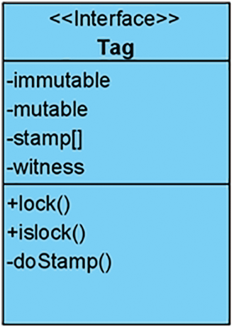
Figure 1: General representation of the log structure
Contextual information, relationships, and immutable data. The hash is calculated and added to a set of variables at any time. To check for changes, a new hash value is calculated and compared to the previous values in this variable set. Consequently, the comparison result determines whether the structure has changed or not. If the results are identical, the structure is not altered; otherwise, the structure has been altered. If a Log has no other Logs in its context, it is referred to as a Suspicious Log, and suspicious Logs are excluded from the context hash calculation. This is an example of a hash finding formula:
Formula (2) depicts the formula for calculating the log context in the design pattern we created. Formula (1) is used to calculate the Logs in the current context.
As can be seen when we look at Formula (2), the context consists of the logs behind which the Log occurs and the relationships between them, how the relationships are meaningful here. That is, contexts with the same Logs but different associations are different. At the same time, a Log can have many contexts. Our proposed design template gives unique summary values for existing contexts, thanks to the summarization function. Summary values expressing different contexts will be stored in a set called stamps in the Log. Any match within the sets of two Logs will be in the matching context. Also, there are essential Logs in a context and unimportant Logs.
The design pattern we created has all indications of the information. This facilitates their accessibility. For instance, if Log2 is required to determine the hash of Log1 and Log1 already has the indicator for Log2, the calculation is straightforward. This demonstrates that the created model can support the graph.
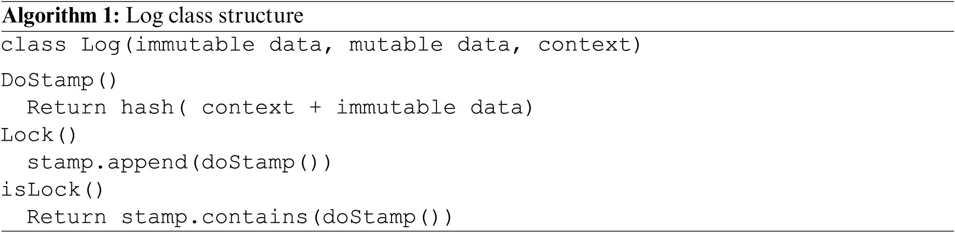
The recommended design pattern also contains two functionalities. The first is a lock(), and the second is an isLock (). Utilizing the Lock function, the system is secured. The Lock computes the context and immutable data hash and adds it to the Stamp set. A different hash value will be generated if there is a change in the system’s logs or immutable data. Therefore, the data’s position will be established automatically regardless of whether it has changed. isLocked is the function that queries this value. The operations conducted are illustrated in Figs. 2 and 3
:
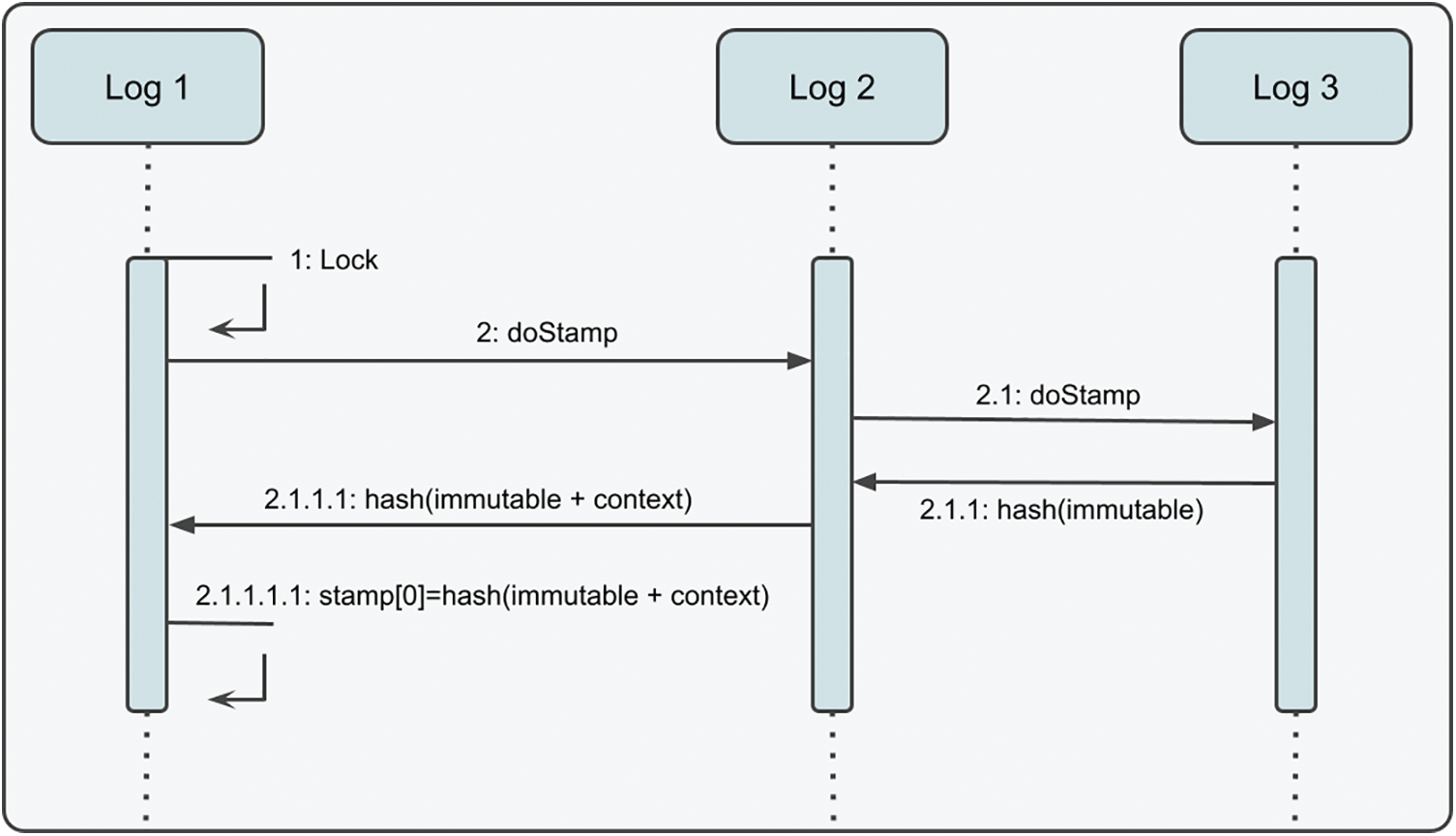
Figure 2: Sequence diagram of Lock
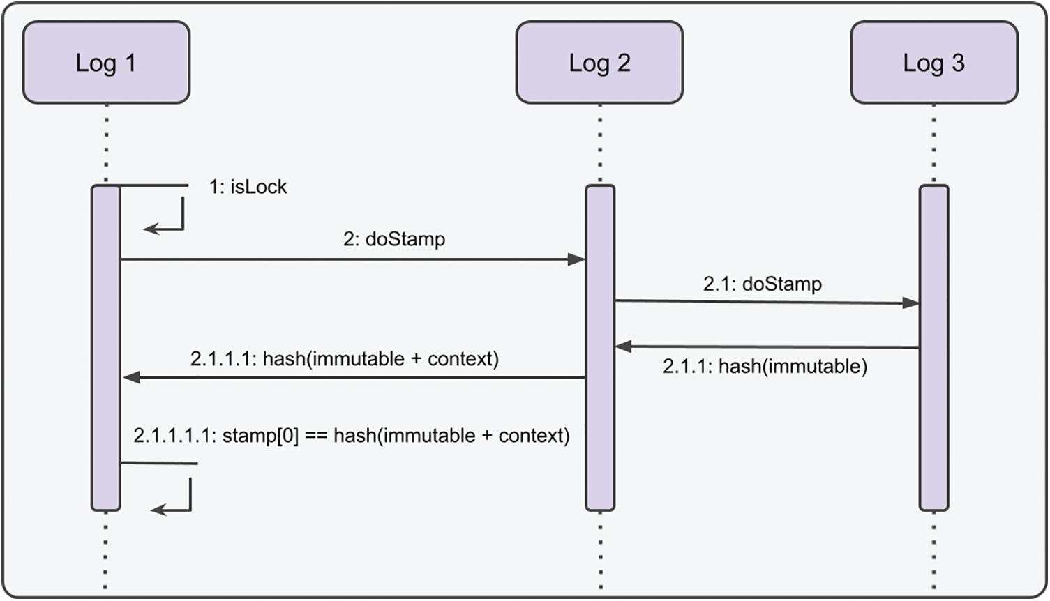
Figure 3: Sequence diagram of isLock
From the standpoint of the design pattern, every class that implements the Tag interface will have the addable but immutable attribute. In the above illustration, the User class uses the Lock feature of Tag to prohibit new additions. Here, tag structures introduced to the tag class can be observed. Similar to the logic of receiving information, other tag structures support the validity of the primary tag structure. Its mutable, immutable, lock, and context characteristics answer all modeling, security, and tracking issues. As far as we know, there is no such design template in software engineering. The general representation of the design pattern is given in Fig. 4.
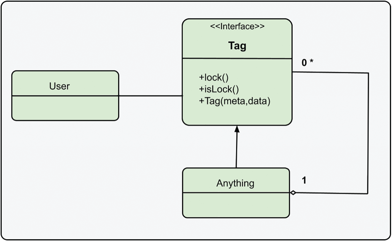
Figure 4: General representation of design pattern
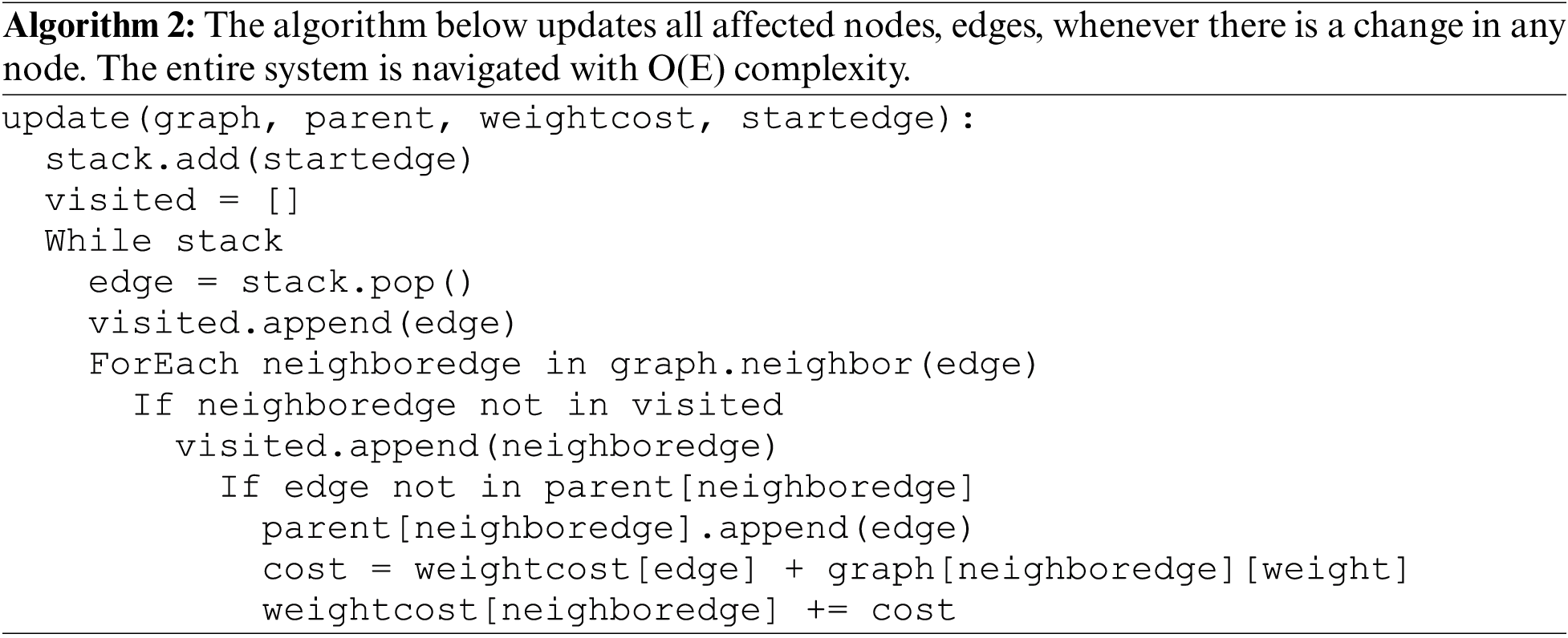
The following Python code was created using dynamic programming and depth-first search. As the system is a multi-di-graph, nodes and edges are exchanged to traverse all transitions. Therefore, all edges are navigable. The entire system is explored with O(E) complexity. Consequently, the entire system is revised with linear complexity.
:
The following pseudo-code (https://github.com/kursuApp/atlas) was created using dynamic programming and depth-first search to update the graph. Since the system is a multi-di-graph, nodes and edges have been exchanged to traverse all transitions. This guarantees that all edges are navigable. The entire system is navigated with O(E) complexity. Consequently, the entire system is revised with linear complexity.
The preceding algorithm aims to transport logs from the current location to all other locations. Logs can be moved to all system locations thanks to the algorithm with minimal effort. Possible threats to the model’s validity are discussed in the following section.
It is impractical to update the entire system and build a new blockchain design because the blockchain comprises layers that perform different jobs. In this essay, therefore, only the data layer of the blockchain is described and modeled. In addition, it was not essential to suggest a new search algorithm within the boundaries of the contributions provided to the data layer. The B+ tree search method was utilized because its success was sufficient in terms of time complexity.
The alternative hypothesis that “the new log system is more successful,” which we proposed in the log design pattern we created, is true because the log structure incorporates the old structure and will deliver greater performance.
The model we created for the study was compared to the blockchain model, and the results were dis- played using a graphical way. Here, the functionality of the model is further demonstrated through example scenarios. All potentially crucial functionality has been evaluated.
The blockchain data structure was deemed appropriate for this project given that the model we developed is a system that sequentially triggers each other and carries information. Due to the blockchain’s limited support for graph structures, the data structure has been modified. In this section, the advantages and disadvantages of the blockchain model are contrasted with those of the model developed for this study.
The size of each block or Log is 10 MB, while the size of each address is 256 bytes. This experimental setup demonstrates that the amount of data to be processed increases linearly with the total number of blocks. In addition, the amount of data processed by the Log mechanism is negligible compared to the traditional blockchain.
The footprint of each block in the blockchain is as follows:
Block size = number of blocks ∗ (data size of the block + address size)
However, in the Logging mechanism we developed, the area occupied by each Log is as follows:
Log size = Number of log s ∗ (2 ∗ address size + stamp size ∗ address size + Log size ∗ address size) Clearly, address sizes are always significantly smaller than the data size of a block. Large amounts of data in the blockchain have an O time and space complexity (n). In contrast, our logging mechanism’s time and space complexity is O(1). Fig. 5 depicts this circumstance.
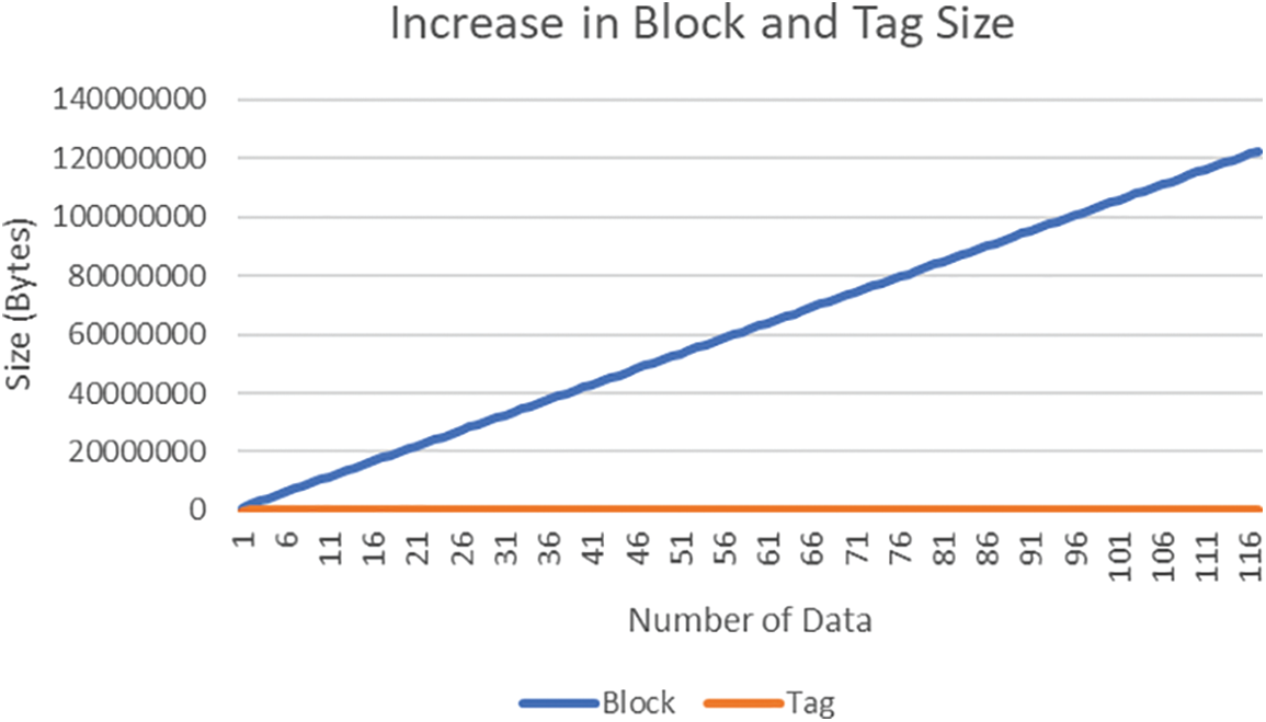
Figure 5: Blockwise vs. Logwise space complexity
In Fig. 5, the stamp size is 10, and the tag/block size is 100. As the increase in tag structure is negligible, it is omitted from the graph. Here, the space complexity of the block structure is O(n), whereas the tag structure is nearly O(1).
Fig. 6 compares the search performance of blocks in the blockchain to that of the proposed Log structure. Due to the linked list structure, the search complexity in a blockchain increases linearly as the number of blocks increases. Alternatively, our proposed Log structure is compatible with all indexing mechanisms. By using B+ Tree for indexing, the search complexity is significantly reduced.
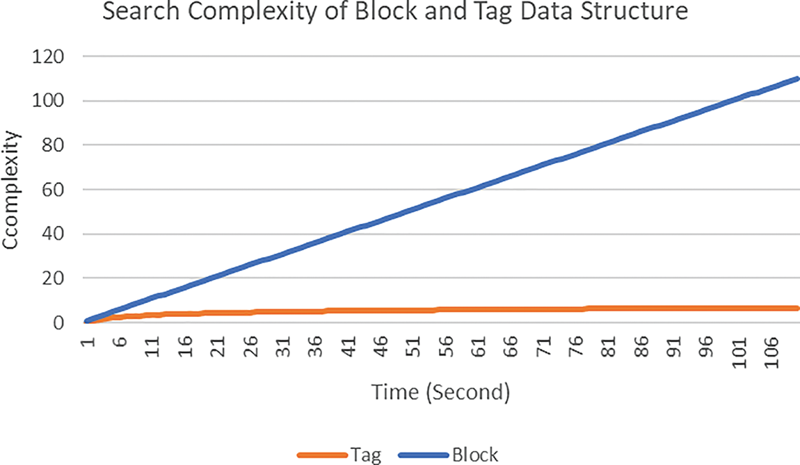
Figure 6: Blockwise vs. Logwise search time complexity
Table 1 lists the advantages of the logging mechanism. By separating the Meta information from the data, it is now possible to easily access this Meta information. In addition, unlike the blockchain, the log structure includes a changeable data structure. Our developed model contains three essential components. The first is the data’s ability to be updated. The second is the separation of data and model, and the third is the trust mechanism. Thanks to all of these contributions, it is straightforward to observe a performance boost as the blockchain grows in size.
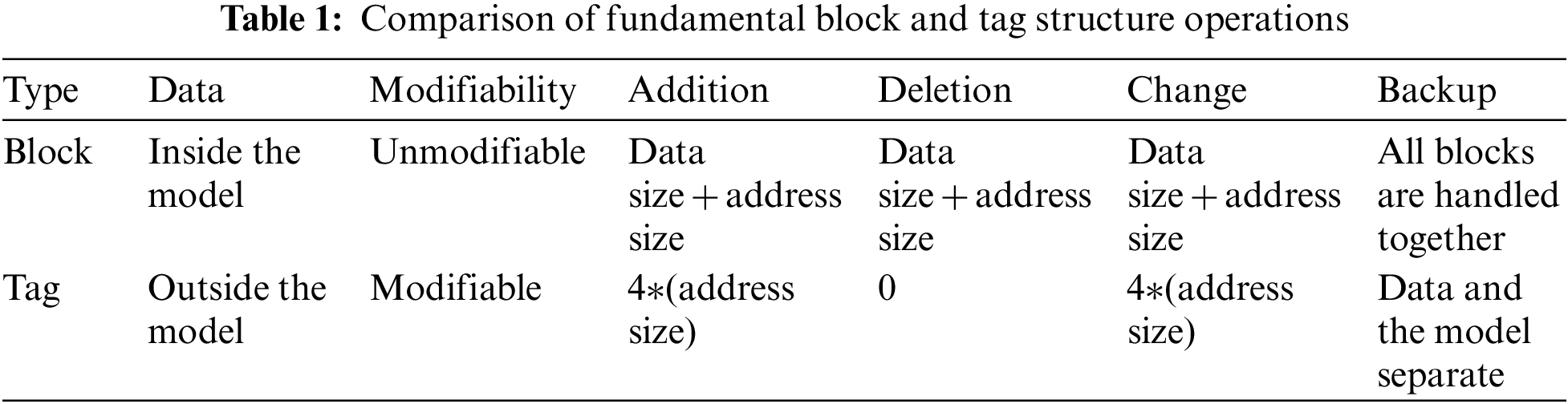
Table 2 the log structure we developed using the blockchain model. Each block in the blockchain is stored using a linked list structure. The blockchain data structure prohibits all other forms of storage. The linked list’s operations are inflexible and cannot be modified. Alternatively, the proposed model has the advantages of flexibility and upgradeability over blocks in a blockchain, as it can accommodate a variety of structures.
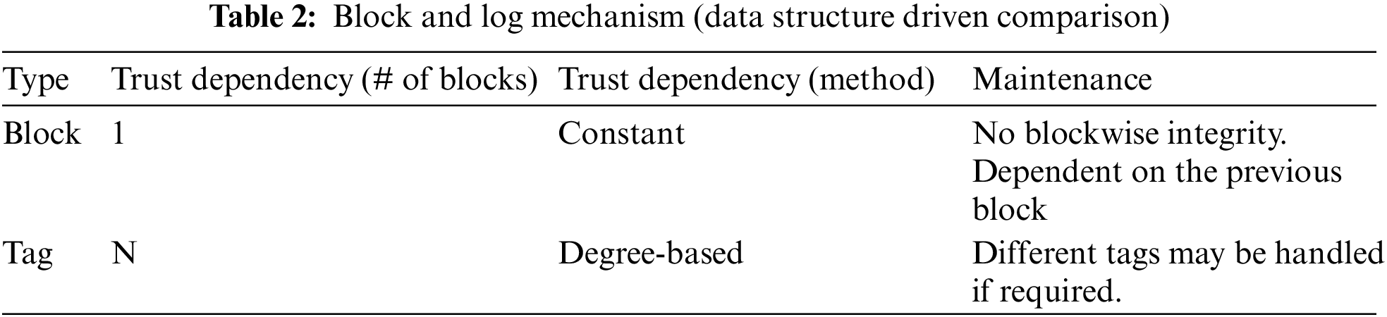
While the links between the blocks prevent them from being moved to different locations in the blockchain, the graph-based flexibility of the log structure we recommend makes it possible to move a log to a different location. Indexing and data portability are also related. While it is difficult to create this indexing in the linked list structure used for standard blocks in the blockchain, the log structure we recommend can easily accommodate all indexing mechanisms.
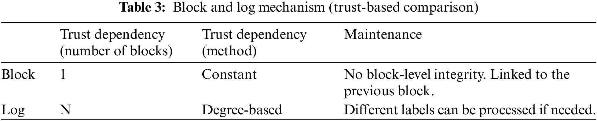
Table 3 examines the two approaches through the lens of trust. Therefore, each block’s trustworthiness depends on the previous block’s reliability, and the blocks’ trustworthiness cannot be achieved gradually or hierarchically. On the other hand, Logs can establish various relationships with one another, and there can be varying degrees of trust between Logs.
Four STM32 and Lora Modules were utilized for the physical testing of the model we developed, and tests were conducted. At this stage, consensus algorithms were not implemented, but tests were conducted on the client-server architecture for storing, searching, and transferring information. Consequently, the model’s physical operability has been determined. The codes can be accessed through GitHub (https://github.com/kursuApp/tag/).
Due to the adaptability and dependability of the Log structure we’ve developed, it is possible to create a practical model. The adequacy of the structure we’ve developed has been demonstrated by applying the scenarios listed below.
While logging, we may not want some information to be logged. Alternatively, it may be necessary to change that information in the future. Therefore, we put that information in variable regions within the model. Although all kinds of calculations can be made on the information in the changeable region, there is no mechanism to guarantee its immutability. If mutable information is desired to be immutable at any time, this operation can be performed with O(E) complexity with the update algorithm given above. Immutable information can be made mutable if desired. This operation can be performed with the same complexity. The critical point here is that we have the hash value of information that is made immutable, and this hash value is known only to the locker. Its hash value will also change when any change to the immutable information. In this case, information can be accessed at what point the information changed and, if desired, how and by whom it was changed.
To demonstrate the invariance, two pieces of information have been created below. Here the context of Log2 is Log1. Log1 has no context at this stage. The pseudo-code used to generate these two pieces of information is as follows:

At the stage shown above, the lock function was not executed. Therefore, as a result, no unalterability mechanism is activated. The stamp values will be zero when the immutability mechanism is not activated. The JSON format view of this structure is as follows:

In the following stage, by calling the lock function of Log2, the system was locked and thus made unchangeable. The command to call log2’s lock function is as follows:

As a result, the structure that Log1 supports Log2 makes Knowledge1 unalterable even if only Log2’s lock function is run. The JSON format view of the structure after Log2’s Lock function is applied as follows. The point to be noted here is that the stamp values are entered. These stamp values are the hash of Log1 and Log2

A new piece of information can be added to the mutable variable if desired, which will not change the stamp value. This will give us tremendous flexibility in creating the context because some information is essential for context, while some information is unimportant. Below is shown in JSON format that the stamp values do not change even though the mutable values change:

If new information is added to the immutable variable when prompted, the hash values will be regenerated, and when these new values are compared with the old values, it will be seen that the newly created hash values are different from the old hash values. The point we want to draw attention to here is that when the immutable value of Log1 is changed, Log2 will also change. This is shown in JSON format below:

Finally, in the model we developed, the changing hash values can be determined very easily at which point the information has changed.
In logging mechanisms, categorical sorting is present. This is not related to the relationships between Logs but rather to the importance that the author of the Log in question places on that Log. Assume that we have a Log. This Log detects a critical error when it receives and combines the signal from a critical region of the software we developed with the signal in its region. By combining seemingly useless logs from various locations within the system, it is possible to detect the presence of a critical error. In addition, this Logging system can reduce the significance of an important event by combining it with other events. Therefore, determining the degree of logs by establishing relationships between logs provides software developers an essential advantage.
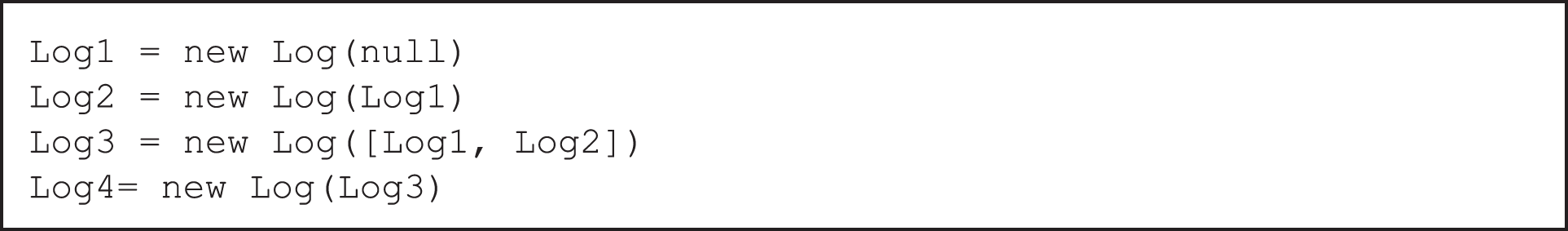
In the developed model, the context of a log influences its reliability. The greater the number of reliable Logs in its context, the greater the Log’s reliability. Suppose there is no context information. This Log is referred to as a suspicious Log. This example demonstrates how to create a Log without any context.

The following example demonstrates how to express multiple contexts using arrays. Two Logs support this Log.

When a change is made to the system, the Log where the change was made will update all the Logs it has modified. It takes advantage of the O(E) complexity update algorithm. Thus, the system remains consistent regardless of the number of changes.
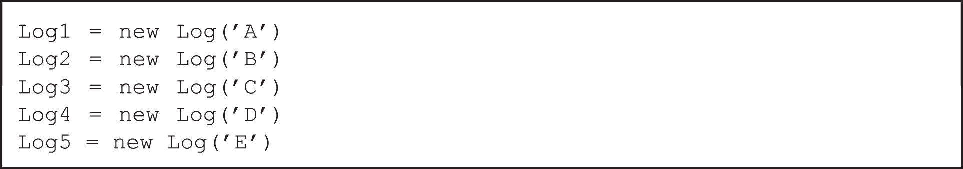
This section provides a basic consistency scenario. First, five Logs are created in this section. At the time that these Logs are created, they lack context. The pseudocode for creating Logs appears below:
After the logs are created, the context between them is established based on the cause and effect relationship. If a Log has no other Logs in its context, it is not reliable. For example, the second, third, and fourth Logs in the code below support the first. Destruction of these Logs will compromise the first Log’s trust networks, rendering it contextless and unreliable. After the cause and effect relationships of the logs are entered in the code below, the Lock function is used to lock the logs. When there is an error or change in the Logs themselves or any Logs that support it, the model isolates the source of the change and removes it from context.
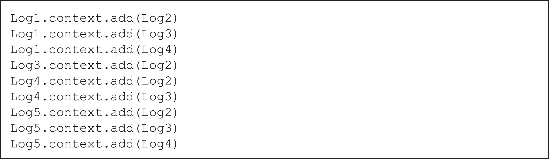
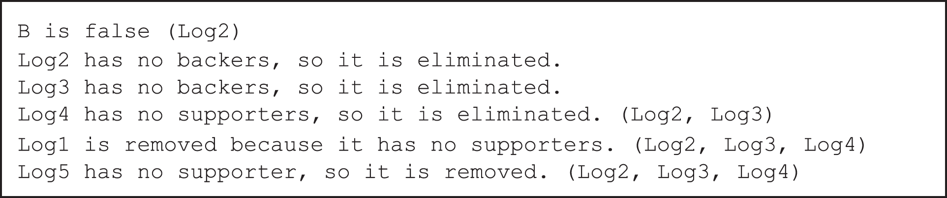
Later, it was discovered that the Log2 information in the created model was incorrect; as a result, the incorrect information was removed from the trusted network. Log3, supported by log2, subsequently became unreliable. Log3’s departure from the web of trust has rendered Log4 unsupported and unreliable. Log4 was consequently removed from the trusted network. Thus, Log1 remained unsupported and abandoned the trusted network. This rendered Log5 unsupported and untrustworthy. As a result, all Logs in the example have become unreliable or removed from the web of trust. This demonstrates how consistency operates.
Even if there is no log in its context, a log might be regarded to exist. This does not affect the system negatively. The model could contain such a Log.
In multi-layer architecture, the context mechanism stores a great deal of information, such as communication between layers, immutability information, or, if there is a change, where it occurred, when and by whom, and the effect of this change on the system. Since the context can be created hierarchically, it provides developers with great design integrity and convenience. Moreover, the context mechanism offers developers a living logging mechanism.
Below are four Logs that explain the context of a Log.
Below is the context created by the Logs listed above. In this instance, Log1 has no context but remains in the model. This indicates there are no Logs available to verify Log1.
Log4 has Log1, Log2, and Log3 in its context. The hash value will be network-specific when calculating the context of Log4 will be specific to Log1, Log2, and Log3 and the relationship between them. Also, since a Log can have many contexts, it is possible to create a set of contexts by throwing the summaries we want into an array. Then, looking at these hash values, whether another log is compatible with its context is understood.
The structure contains many loops in the example below. Since the update algorithm uses the deep first search (DFS) method, it cannot travel a path it has traveled again, and the loop problem will be eliminated. Another point is that since the model and the data are separated, the data structure can easily use the graph data structure.
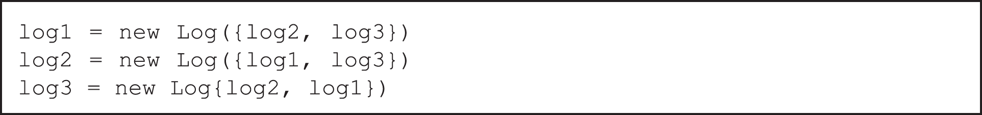
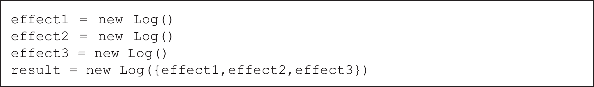
The developed model can easily model many different structures thanks to its flexible data structure. In this way, it provides us with the necessary infrastructure to make inferences. For example, if we want to express a situation where the verb and object directly support the Subject, we can create a structure like this:

When we want to create a cause-effect relationship, it is possible to do so with a structure like this:
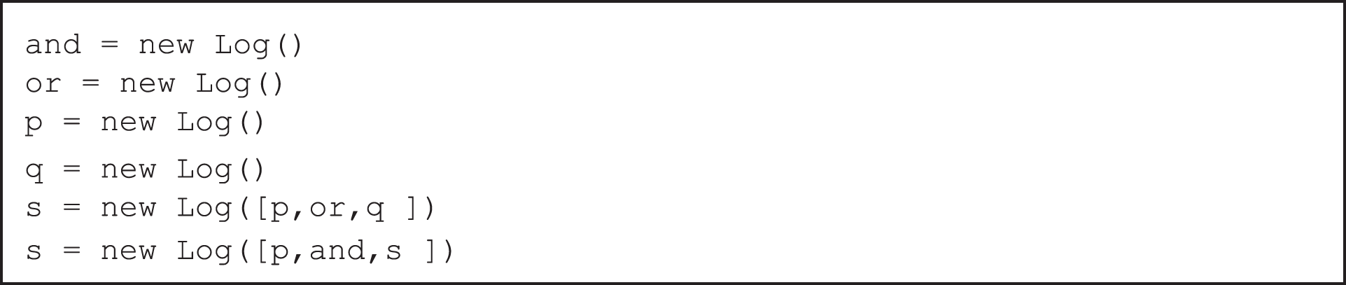
Any logical expression can be implemented as follows:
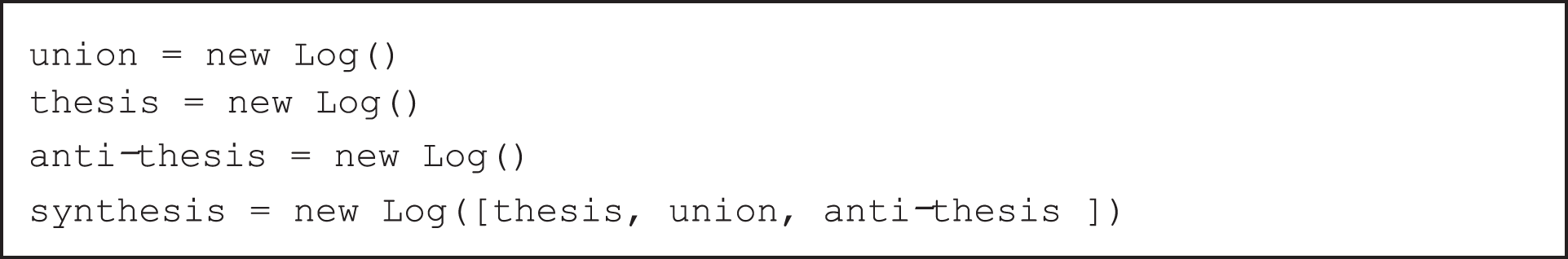
Finally, it is possible to show the thesis, antithesis, and synthesis structures as follows
With the Logging system I have developed, it is possible to implement many different features that are not included here. As the applications in which this system is integrated increase, it is possible to develop the system by adding new features in line with the system’s needs.
In software engineering, the process of acquiring log-related information occurs during the software period, independent of the relationship between events. However, as with the event concept, there are relationships. A new relational log design pattern has been developed from this perspective.
In software engineering, the proposed design pattern was compared to the blockchain’s data structure in traceability and observability. The system’s functionality was evaluated based on “immutability, dependability, consistency, context, and inference” In terms of time and space efficiency, it has been determined that the proposed structure outperforms blockchain technology.
In contrast to other methods, our log design pattern emphasizes the interaction between events. Thus, the design pattern we created enables the creation of complex relationships between logs and the derivation of conclusions from them. In addition, the log design pattern we created is interactive, and this two-way communication facilitates the system’s remote control. It also enables the extraction of complex information inferences. Integrating the log system with the software, the log structure, typically used during compilation, is actively utilized during runtime.
The suggested log design pattern may be utilized throughout the design phase and all software engineering processes. It is embedded in the code, participates in the decision-making mechanisms of logical processes, and ensures that the software is observable and traceable even after the product has been delivered to the end user. In this context, it is anticipated that the log design pattern we propose will contribute to problem-solving, particularly in large-scale software projects, by supporting the methods used to monitor software projects and guaranteeing the traceability of relationships.
Funding Statement: The authors received no specific funding for this study.
Conflicts of Interest: The authors declare they have no conflicts of interest to report regarding the present study.
References
1. S. Karumuri, F. Solleza, S. Zdonik and N. Tatbul, “Towards observability data management at scale,” ACM Sigmod Record, vol. 49, no. 4, pp. 18–23, 2021. [Google Scholar]
2. S. Munawar, R. Yousaf and M. Hamid, “Extended scrum process model using software reliability engineering concerns,” Journal of Information Communication Technologies and Robotic Applications, vol. 8, no. 2, pp. 1–10. 2018. [Google Scholar]
3. M. Hamid, F. Zeshan, A. Ahmad, S. Munawar, E. Aimeur et al., “An intelligent decision support system for effective handling of IT projects,” Journal of Intelligent & Fuzzy Systems, vol. 38, no 3, pp. 2635–2647, 2020. [Google Scholar]
4. S. Niedermaier, F. Koetter, A. Freymann and S. Wagner, “On observability and monitoring of distributed systems,” in Proc. of the Int. Conf. on Service-Oriented Computing, Toulouse, France, vol. 11895, pp. 36–52, 2019. [Google Scholar]
5. K. Indrasiri and P. Siriwardena, Microservices for the Enterprise: Designing, Developing, and Deploying, 1st ed., vol. 1. Berkeley, CA, USA: Apress, pp. 441, 2018. [Google Scholar]
6. D. Meißner, “Towards time travel in distributed event-sourced systems,” in Proc. of the 12th ACM Int. Conf. on Distributed and Event-Based Systems, Hamilton, New Zealand, pp. 266–269, 2018. [Google Scholar]
7. C. Majors, L. Fong-Jones and G. Miranda, Observability Engineering: Achieving Production Excellence, 1st ed., vol. 1. Sebastopol, California, USA: O’Reilly Media, Inc., pp. 318, 2022. [Google Scholar]
8. S. R. Goniwada, “Cloud native architecture and design patterns,” in Cloud Native Architecture and Design Patterns, 1st ed., vol. 1. Berkeley, CA, USA: Apress, pp. 127–187, 2022. [Google Scholar]
9. M. Chakraborty and A. P. Kundan, “Observability,” in Monitoring Cloud-Native Applications, 1st ed., vol. 3. Berkeley, CA, USA: Apress, pp. 25–54, 2021. [Google Scholar]
10. D. Meißner, D. B. Erb and F. Kargl, “Performance engineering in distributed event-sourced systems,” in Proc. of the 12th ACM Int. Conf. on Distributed and Event-Based Systems, Hamilton, New Zealand, pp. 242–245, 2018. [Google Scholar]
11. R. Gatev, “Observability: Logs, metrics, and traces,” in Introducing Distributed Application Runtime (Dapr), 1st ed., vol. 1. Berkeley, CA, USA: Apress, pp. 233–252, 2021. [Google Scholar]
12. W. N. Robinson, “A requirements monitoring framework for enterprise systems,” Requirements Engineering, vol. 11, no. 1, pp. 17–41, 2006. [Google Scholar]
13. A. Boten and C. Majors, Cloud-native Observability with OpenTelemetry: Learn to Gain Visibility into Systems by Combining Tracing, Metrics, and Logging with OpenTelemetry, 1st ed., Birmingham, UK: Packt Publishing Ltd., pp. 386, 2022. [Google Scholar]
14. B. Li, X. Peng, Q. Xiang, H. Wang, T. Xie et al., “Enjoy your observability: An industrial survey of microservice tracing and analysis,” Empirical Software Engineering, vol. 27, no. 1, pp. 25, 2022. [Google Scholar]
15. A. Shafiq, A. Mashkoor, C. Mayr-Dorn and A. Egyed, “A literature review of machine learning and software development life cycle stages,” IEEE Access, vol. 9, pp. 140896–140920, 2021. [Google Scholar]
16. S. R. Goniwada, “Observability,” in Cloud Native Architecture and Design, 1st ed., vol. 1. Berkeley, CA, USA: Apress, pp. 661–676, 2022. [Google Scholar]
17. J. Levin and T. A. Benson, “ViperProbe: Rethinking microservice observability with eBPF,” in 2020 IEEE 9th Int. Conf. on Cloud Networking (CloudNetIEEE, Piscataway, NJ, USA, pp. 1–8, 2020. [Google Scholar]
18. I. Tzanettis, C. M. Androna, A. Zafeiropoulos, E. Fotopoulou and S. Papavassiliou, “Data fusion of observability signals for assisting orchestration of distributed applications,” Sensors, vol. 22, no. 5, pp. 1–21, 2022. [Google Scholar]
19. B. Erb, D. Mei, F. Ogger and F. Kargl, “Log pruning in distributed event-sourced systems,” in Proc. of the 12th ACM Int. Conf. on Distributed and Event-Based Systems, Hamilton, New Zealand, pp. 230–233, 2018. [Google Scholar]
20. R. Bharathi and R. Selvarani, “Machine learning approach for quantifying the design error propagation in safety critical software system,” IETE Journal of Research, vol. 68, no. 1, pp. 467–481, 2022. [Google Scholar]
Cite This Article
 Copyright © 2023 The Author(s). Published by Tech Science Press.
This work is licensed under a Creative Commons Attribution 4.0 International License , which permits unrestricted use, distribution, and reproduction in any medium, provided the original work is properly cited.
 Downloads
 Citation Tools