
 Submit a Paper
 Propose a Special lssue
 Open Access
ARTICLE

Three-Dimensional Analytical Modeling of Axial-Flux Permanent Magnet Drivers
1 Northeastern University, Shenyang, 110819, China
2 Shenyang Polytechnic College, Shenyang, 110819, China
* Corresponding Author: Dazhi Wang. Email:
Computers, Materials & Continua 2023, 75(1), 259-276. https://doi.org/10.32604/cmc.2023.034622
Received 22 July 2022; Accepted 22 September 2022; Issue published 06 February 2023
 View Full Text
 Download PDF
Abstract
In this paper, the axial-flux permanent magnet driver is modeled and analyzed in a simple and novel way under three-dimensional cylindrical coordinates. The inherent three-dimensional characteristics of the device are comprehensively considered, and the governing equations are solved by simplifying the boundary conditions. The axial magnetization of the sector-shaped permanent magnets is accurately described in an algebraic form by the parameters, which makes the physical meaning more explicit than the purely mathematical expression in general series forms. The parameters of the Bessel function are determined simply and the magnetic field distribution of permanent magnets and the air-gap is solved. Furthermore, the field solutions are completely analytical, which provides convenience and satisfactory accuracy for modeling a series of electromagnetic performance parameters, such as the axial electromagnetic force density, axial electromagnetic force, and electromagnetic torque. The correctness and accuracy of the analytical models are fully verified by three-dimensional finite element simulations and a 15 kW prototype and the results of calculations, simulations, and experiments under three methods are highly consistent. The influence of several design parameters on magnetic field distribution and performance is studied and discussed. The results indicate that the modeling method proposed in this paper can calculate the magnetic field distribution and performance accurately and rapidly, which affords an important reference for the design and optimization of axial-flux permanent magnet drivers.Keywords
1.1 Application of PMD in Electric Drive System
The shaft alignment between the prime mover and the load in an electrical transmission system is a critical and difficult issue in installation, operation, and maintenance. As shown in Fig. 1, the shaft misalignment is generally classified as parallel misalignment (represented by γ), angular misalignment (represented by β), and a combination of the two types of misalignments. It has been proved that the alignment quality of shafts affects the exertion of equipment efficiency and service life directly.
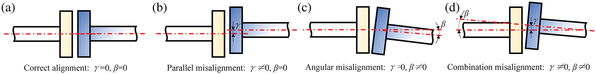
Figure 1: Description of driveshaft alignment problems. (a) Correct alignment; (b) Parallel misalignment; (c) Angular misalignment; (d) Combination misalignment
The permanent magnet driver (PMD) is a new type of connection equipment tailored for the alignment problem of transmission systems. The torque is transmitted through the reciprocity between magnetic fields, realizing non-contact transmission of energy [1]. Therefore, the requirements for the connection accuracy between the motor and the load are greatly reduced without affecting the normal working. Also, the ability to transmit energy and control speed is not influenced by the small-angle or small offset of shafts. In addition, PMD also reduces the mechanical vibration and noise caused by the mechanical connection of rigid bodies. It plays an irreplaceable role in transmission systems of many industrial fields with a high-temperature difference, high humidity, corrosiveness, and dust [2].
As shown in Fig. 2, PMDs are divided into the radial-flux type and axial-flux type according to different magnetic flux paths [3]. Compared with the axial-flux topology, the torque density of the radial-flux permanent magnet driver (RPMD) is higher, but the structure is more complex and the air-gap cannot be adjusted. In addition, the inner and outer rotors must be precisely aligned to maintain the force balance, which puts more stringent requirements on the mechanical structure [4]. Therefore, this paper takes the axial-flux permanent magnet driver (APMD) as the research objective, a kind of device with a compact structure, convenient installation, great heat dissipation, and adjustable air-gap.
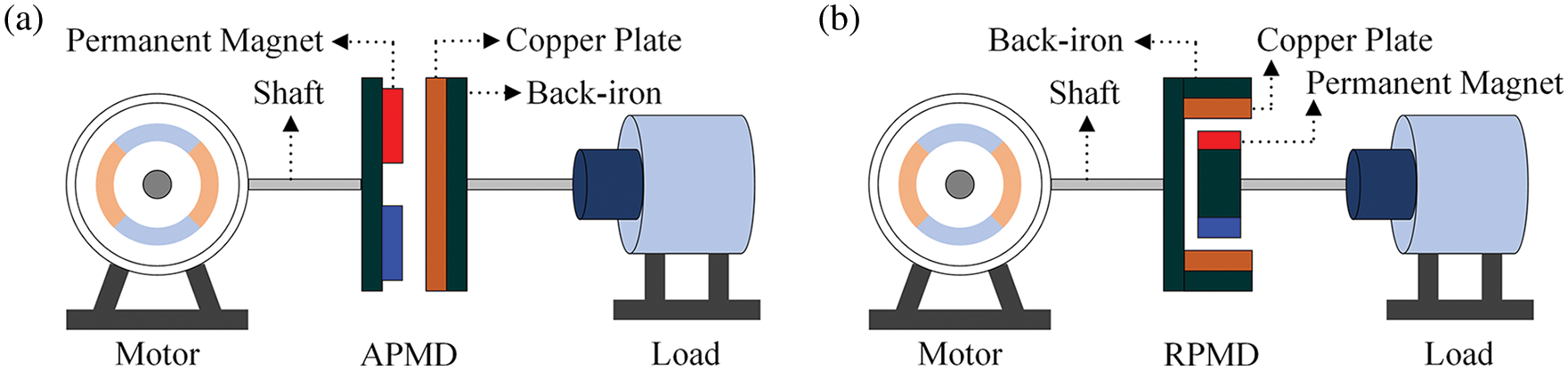
Figure 2: Two types of PMD. (a) Topology diagram of APMD; (b) Topology diagram of RPMD
1.2 Overview of Research Methodologies on APMD
For rotating electromagnetic devices such as drivers, motors, and actuators, being accurately modeled is the basis of optimization and novel topologies. Benefiting from the development of existing modeling methods, the difficulty of solving the eddy current (EC) problem, magnetic field (MF), and torque on the conductor rotor (CR) is greatly reduced. According to the different core ideas, the main modeling methods include numerical analysis method (NAM), spectral element method (SEM), and analytical analysis method (AAM) [2,5,6].
NAM is a discretization-based problem, which enables the analysis and research of electromagnetic field problems from the classical methods of the continuous system to the discrete systems, and realizes the acquisition of high-precision discrete solutions through computer-aided analysis [7–9]. Compared with AAM, the calculation results of FEM are more accurate and closer to the actual measurement results, and the magnetic saturation characteristics of the back-iron materials can be simulated [10,11]. However, the structural parameters need to be modified frequently in the optimization design of PMD, and it will cause a waste of time if FEM is adopted [12,13].
SEM can be regarded as a generalization of FEM with a special selection of quadrature integration points and nodal points [14]. Compared with FEM, SEM achieves high precision calculation results with lower CPU time and memory computation cost by defining concepts such as the “perfectly matched layer (PML)” and “domain truncation” [15].
Although AAM is not as accurate as NAM, it can reflect the influence of design parameters on equipment performance clearly and save a lot of calculation time. Therefore, it can still be used as a fast analysis tool for performance prediction, design, and optimization processes. According to different modeling principles, there are mainly two analytical methods for APMD enumerated as follows.
1.2.1 Separation Variable Method (SVM)
To predict the performance of APMD accurately, the three-dimensional (3-D) effect of the equipment cannot be ignored. From the modeling point of view, APMD is an inherently 3-D cylindrical structure. Therefore, it is necessary to combine the Dirichlet boundary condition, Neumann boundary condition, and Hankel transform to solve the Laplace equation based on SVM in 3-D cylindrical coordinates. Naturally, the Bessel function is included in the results, which contains many unknown independent variables and multiple complex coupling relationships [16]. Hence, this method will be more popular among researchers if the parameter determination process can be simplified.
1.2.2 Equivalent Magnetic Circuit (EMC)
Inspired by the circuit theory, EMC transforms the MF calculation problem into the magnetic circuit analysis and builds a magnetic circuit network. EMC has also been applied in the optimization design of APMD. The output torque, moment of inertia, and volume are optimized by establishing an EMC-based analytical model [17]. Compared with other methods, EMC not only considers the properties and characteristics of materials but also provides a clear analytical relationship between performance and structural parameters [18]. However, the magnetoresistance varies with structural parameters, it is difficult to predetermine the exact value of the magnetic flux path and the magnetoresistance of each region. The magnetic circuit can only be established depending on the designer’s experience without a theoretical foundation and only the approximate solution can be obtained, which cannot get the precise distribution of MF and EC, thus affecting the calculation accuracy of the model [19].
This paper intends to establish an accurate and comprehensive analytical model for APMD in 3-D cylindrical coordinates, including ontology modeling and performance calculation. The governing equations are solved by simplifying the boundary conditions, an attempt is made to describe the axial magnetization of sector-shaped permanent magnets (PMs) in an explicit algebraic form instead of the existing complex series expressions. The establishment of this algebraic model can greatly improve the calculation speed. The boundary of the computational domain is determined according to the domain truncation theory in SEM, which effectively saves computational costs and time. The parameters of the Bessel equation are determined simply and the MF distribution of PMs and the air-gap is solved. Finally, the performance parameters of APMD are obtained, including the axial electromagnetic force density (AEFD), the axial electromagnetic force (AEF), and electromagnetic torque. To verify the accuracy of the analytical models comprehensively proposed, the 3-D finite element simulation model and an experimental platform are established. The influence of several design parameters on the MF distribution is studied, and universal conclusions are obtained.
2 Topology Configuration of APMD and Modeling Assumptions
Cutting and expanding along the radius of the APMD in cylindrical coordinates and establishing the “five-layer structure” shown in Fig. 3 have been shown to be effective for modeling [3]. This paper attempts to extend the five-layer model into cylindrical coordinates that are more consistent with the closed geometry inherently of APMD. The main assumptions are proposed within a reasonable range.
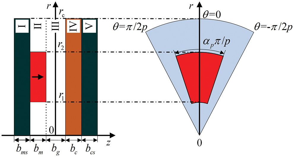
Figure 3: Geometric schematic diagram of APMD in cylindrical coordinates
2.1 Topology Configuration and Operating Principle of APMD
APMD consists of the PM rotor (PMR) and CR mounted oppositely. The PMR is composed of PM blocks and a back-iron plate (BRP). The axially magnetized PM blocks with even-number alternately placed along θ-direction. The BRP is configured to provide closed flux paths and mechanical support. The CR mainly consists of a BRP and a conductor plate placed coaxially. The conductor plate is usually made of metal materials with high conductivity to generate as many induced currents as possible. There is a certain air-gap between PMR and CR, which makes the connection between the prime mover and the load non-contact and flexible.
The operation of APMD obeys Lenz’s law. As shown in Fig. 2a, PMR is dragged by the prime mover, resulting in the relative motion with CR. The alternating MF induces EC in the conductor through the air-gap. The EC reaction field interacts with the PM field, but CR is still in a static state due to the torque of load. When the slip angle between CR and PMR reaches a certain value, the original static equilibrium state of the system will be broken. The electromagnetic torque increases with the increase of the slip angle until the load torque is exceeded, and CR starts to rotate and drive the load. The maximum load torque that APMD can bear is determined by the peak value of its static torque characteristics. If the peak value is exceeded by the load torque, a phenomenon similar to the motor out-of-step will occur, which will cause the load to be separated from the prime mover, thus playing the role of overload protection.
APMD is modeled in 3-D cylindrical coordinate due to the natural cylindrical boundary. As shown in Fig. 4, the 1/2 air-gap is selected as the origin of coordinates, and the directions of r, θ, and z represent radial, circumferential and axial directions, respectively. To improve the universality of the model, some assumptions are proposed to set the properties and necessary conditions of complex materials.
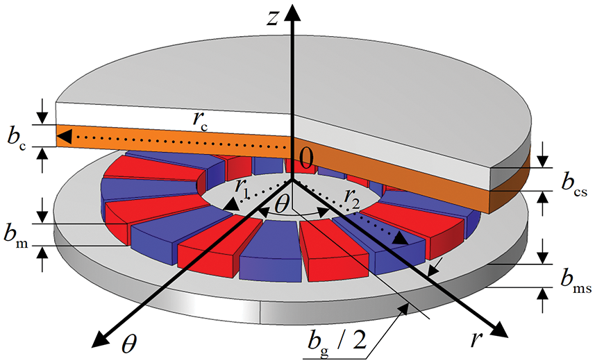
Figure 4: APMD model in 3-D cylindrical coordinates
a) The electromagnetic torque and EC on the back-iron of the copper plate can be ignored.
b) The materials from region Ⅱ to region IV are uniform and the relative permeability is constant. The permeability of region I and region V is infinite and the conductivity of both regions is zero.
c) The permeability of region I and region V is infinite and the conductivity of both regions is zero.
d) PMs are magnetized along the z-direction, and the residual magnetic density is only the component of the z-direction.
According to the topology and operating principle of APMD, the z-direction magnetic flux density (MFD) is the main flux producing electromagnetic torque. The conductivity of the back-iron material is much smaller than that of the copper plate, hence, the resulting electromagnetic torque is also negligible compared to them later. In summary, the electromagnetic torque and EC in BRP can be ignored, therefore, the first assumption is reasonable.
3 Analytical Modeling of APMD in 3-D Cylindrical Coordinates
It can be seen from the comparison of several main AAM mentioned in 1.2 that if the parameter determination process of the Bessel function can be simplified, the modeling method based on SVM to solve the Laplace equation can reach the highest accuracy and the best effect when considering the 3-D effects of devices. In this section, the complex boundary conditions of APMD are simplified to solve the Laplace equation. In addition, the geometric representation of sector-shaped PMs and the parameters of the Bessel function are determined. Through the MFD expression of the air-gap and PMs in 3-D cylindrical coordinates, the expressions of AEFD, AEF, and torque are derived ulteriorly.
3.1 Governing Equations and Boundary Conditions in 3-D Cylindrical Coordinates
In homogeneous media, the constitutive relationship of APMD can be described by MFD and the magnetic field intensity (MFI), denoted by
where μ0 is the vacuum permeability and μi is the relative permeability of each layer, unless stated otherwise,
In the five-layer diagram of APMD shown in Fig. 3, the current distributes in region IV only, and the others are non-current regions, satisfying the basic equation of MF distribution in (3). It is difficult to solve MFI directly. To reduce the difficulty of MF calculation, the scalar magnetic potential (SMP)
Theoretically, in the area covered by MF lines, SMP exists everywhere until it disappears at infinity. Therefore, it is necessary to set the magnetic insulation boundary condition (6) for the back-iron of PM. However, most of the magnetic flux of APMD closes along the main magnetic circuit between PM and the copper plate in practice, while a small portion of leakage flux closes itself along different paths near PMs. Inspired by the concepts of “perfectly matched layer” and “domain truncation” in SEM, the position at a tenth of the outer radius of PM is defined as the zero SMP [20,21]. Such a selection method can not only guarantee that MF is fully calculated, but also saves a lot of computation time and cost [22].
The permeability of back-iron is assumed to be infinite, the tangential component of MF at z = −bg/2 − bm and z = bg/2 + bc is zero naturally. At the interface between PM and the air-gap, the tangential component of MFI and the normal component of MFD cannot change abruptly, otherwise, the Continuity principle of flux and the Ampere circuital theorem will be violated. The boundary conditions (8) and (9) can be obtained by considering the constitutive relation of APMD and the connection conditions at the interface of different media.
The boundary of the z-direction has been specified in (8). To facilitate the later solution of PMs, MFI and MFD are considered as the boundary conditions in both the r and θ directions.
From the symmetry shown in Fig. 2a, it can be found that the magnetic potential varies periodically concerning the variable θ by 2π/p in the θ-direction. In region Ⅱ and region ⅡI, SMP satisfies the Laplace Eq. (5) and is calculated by SVM. Although the accuracy of solving field equations by SVM is satisfactory, the Bessel function is involved. When solving the Laplace equation in cylindrical coordinates, the general solutions of field equations are the cylindrical harmonic function composed of the first kind of n-order Bessel function, the second kind of n-order Bessel function, and other functions. In addition, it contains a series of numerous and jumbled parameters, and the expansion coefficients of the Bessel function are quite difficult to determine directly. In this paper, the MF distribution characteristics of APMD and its geometric characteristics in axial, circumferential, and radial directions in 3-D cylindrical coordinates are considered. The cylindrical harmonic function is reasonably simplified to obtain a common form including the general solution of the Bessel function [18].
where n is the order of Bessel function, Fnp (qr) is the first kind of n-order Bessel function, q and Wni are design variables that are related to the APMD topology and are independent of the location coordinates.
Since there is no current distribution involved in PMs, the magnetic charge model located at z = −bg/2 can be used to calculate the analytical solution of 3-D MF. The N and S poles of PMs are characterized by the surface magnetic charges of equal magnitude and opposite polarity in the r−θ plane shown in Fig. 5, respectively. The surface magnetic charge density (MCD) can be expressed by the ratio of residual MFD Br and the vacuum permeability μ0 [2].
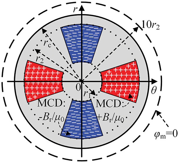
Figure 5: Surface magnetic charges on PMs
Based on the surface magnetic charge theory of PM and boundary conditions, Eq. (14) is established by introducing the Fourier-Bessel series, and the unknown coefficient Wni can be obtained smoothly. Once Wni is determined, the axial magnetization of sector-shaped PMs can be resolved through an explicit algebraic form rather than a complex series expression, which is of great significance to the modeling and optimization of APMD. The expressions of MFD of region Ⅱ and region ⅡI in 3-D cylindrical coordinates can be obtained by applying the models and constitutive relations (1), (3), and (4).
3.3 Calculations of External Characteristics
At present, there are three main methods to calculate electromagnetic force: Lorentz force method, Maxwell stress tensor (MST) method, and classical virtual work principle. The MFD models of the air-gap and PMs have been established above, AEF on each rotor can be calculated by integrating MFD on a specific surface using MST [23]. As a simple and fast method, AEF can be calculated if the MFD distribution at the corresponding location is known. To reflect the AEF distribution of APMD more intuitively, this paper first calculates AEFD of the rotor discs. The electromagnetic force is one of the main factors causing the deformation, vibration, and additional noise, and is the main target of the design, analysis, and optimization of APMD. The electromagnetic force can be accurately calculated by MST based on the previous MFD model. It should be noted that in the final expression of the electromagnetic force, the radial MFD is neglected due to the negligible value. The torque of APMD obtained by MST can be calculated according to [24].
4 Parameter Sensitivity Analysis, Comparisons and Discussions
In this section, the parameter sensitivity analysis will be carried out, and the analytical, simulated, and experimental results will be compared, analyzed, and discussed to verify the correctness and accuracy of the proposed model. This section contains the following three parts. In the first part, the statistical learning in data processing is expounded, and the APMD is meshed based on 3-D FEM. The second part studies the influence of design parameters on MF and AEFD distributions of APMD. The relationship between several design parameters and temperature rise, the sinusoidal degree of the air-gap MFD, and torque are comprehensively considered, which lays a foundation for optimization. In the third part, the torque-slip speed characteristics of APMD are studied and verified by simulations and experiments.
4.1 Data Processing and 3-D Meshing
To reflect the distribution pattern of simulation and experimental results more intuitively, statistical methods are used to post-process the data. Construct a fitting function f(x) for all functions with second-order continuous derivatives that minimize the value of the following residual sum-of-squares equation.
where λ is a constant coefficient. Considering that the second-order derivative is the gradient of the slope of the function at a certain point, the larger the second-order derivative, the more tortuous the trend of the function curve. Therefore, the value of λ can be considered from the following two limiting cases:
a)
b)
In short, the fitting function f(x) that meets the requirements can be found in the interval
A 3-D finite element analysis is carried out to validate the proposed analytical method. The 3-D meshing of APMD with five pairs of poles and its single-pole decompositions are constructed according to the specifications of the corresponding prototype (as exhibited in Fig. 6). The interactions among the magnetic poles can be effectively considered by imposing boundary conditions. It is essential to simulate MF induced by EC on the copper plate precisely, so the mesh is set to a high level of refinement for the copper plate, but this will undoubtedly increase the computational cost distinctly. The meshes are set to be relatively coarse for the two BRPs since they do not experience magnetic saturation.
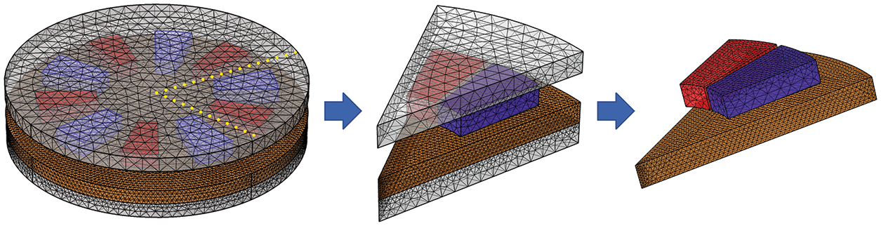
Figure 6: 3-D meshing and single-pole decompositions of APMD
4.2 Influence and Comparisons of Variable Design Parameters on Axial MFD Distribution
The influence of APMD parameters on MF distribution is studied in different coordinate directions, and the accuracy of analytical models is verified by finite element simulations. It can be seen that the analytical results demonstrate excellent consistency with the finite element results. According to the operation process of APMD, the electromagnetic torque is mainly transmitted in the axial direction. The transfer torque is affected by the strength of axial MFD directly, therefore, this section verifies the axial MFD mainly.
When the copper plate is at rest, the MFD distribution in the z-direction obtained from the 3-D steady-state finite element simulation is explicitly shown in Fig. 7. The MFD distributes in a sector-shaped area in the copper disk, which corresponds to the arrangement of PMs one by one, and the polarities are also alternately arranged. The finite element simulation results of the static MFD show that EC will be induced on the copper plate when it moves relative to PMR. EC forms closed loops in the copper plate, and the number of closed loops is equal to the number of magnetic poles of PMs. Furthermore, the direction of EC in the loops is related to the polarity of PMs.
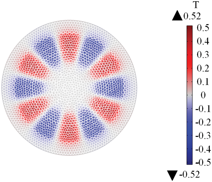
Figure 7: Distribution of axial MFD on copper plate
APMD transmits torque through the air-gap and regulating the thickness of the air-gap to an appropriate value enables the best performance of the device to be exerted. Therefore, it is crucial to study the relationship between the thickness of the air-gap and the MF distribution, the results are demonstrated in Fig. 8. The axial MFD is approximately sinusoidally distributed along the θ-direction. The higher the sinusoidal degree of the air-gap MFD is, the smaller the corresponding harmonic loss is and the higher the output torque is. In addition, there exists such a mapping relationship in APMD: a small air-gap thickness corresponds to the large MFD and EC density, which is macroscopically represented as a higher torque value. However, in practical applications, the torque performance cannot be pursued alone but ignores the heating problem of the copper plate. Once the temperature rise of the copper plate is too high, it will lead to irreversible demagnetization of PMs and deteriorate the electromagnetic performance of APMD. It can be seen that the loss generated by the electromagnetic field acts as a heat source to cause temperature rise, which in turn affects the distribution and loss of the electromagnetic field. There is a strong coupling relationship between electromagnetism and temperature rise [25]. Therefore, it is surely necessary and meaningful to conduct electromagnetic-temperature field coupling analysis on APMD.
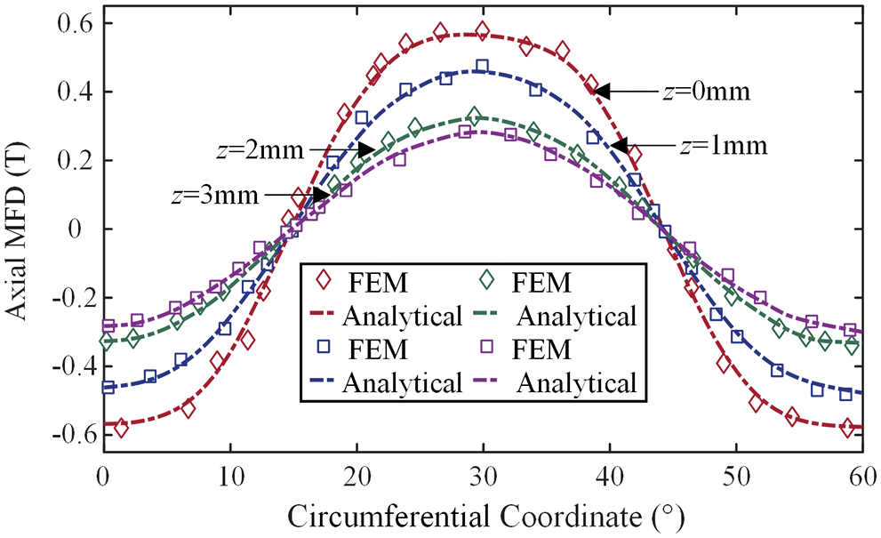
Figure 8: Relationship between the multiple air-gap thicknesses and axial MFD
The relationship between the inner radius of PMs and the axial MFD of APMD can be seen in Fig. 9. Within a certain range, the longer the inner radius of PM, the greater the axial MFD. Beyond this range, they are negatively correlated, which is consistent with the results of [26]. Therefore, the good coordination between equipment performance and structural parameters is critical for developing the performance of APMD, which has also become an item that must be considered in the process of parameter optimization [25].
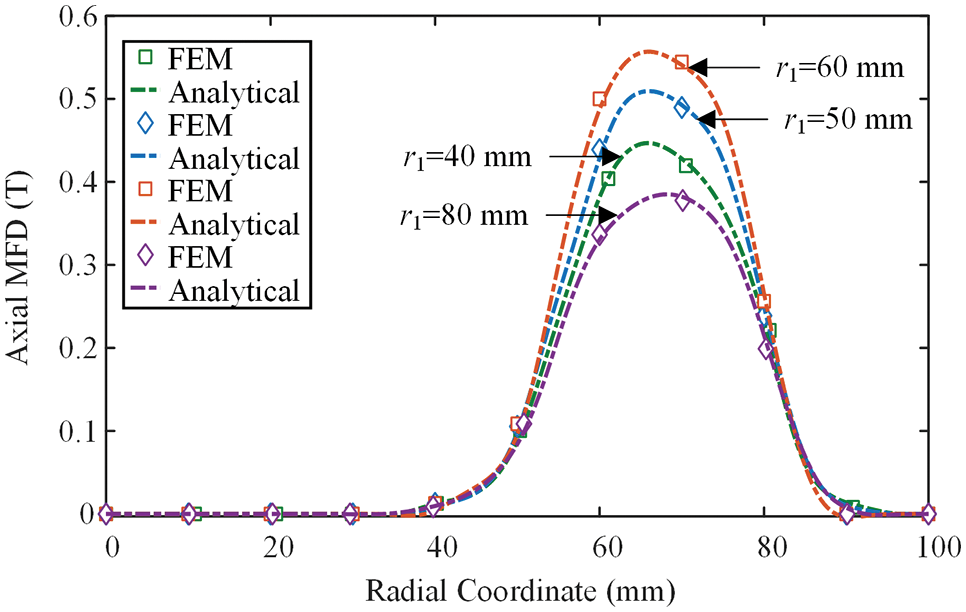
Figure 9: Trends of axial MFD under a range of PM inner radii
As a coefficient describing the actual distribution of the air-gap MF within a pole pitch, the pole-arc coefficient is inseparable from MFD and can be clearly shown in Fig. 10. In this paper, the relationship between the pole-arc coefficients and MFD is studied under the condition of uniform air-gap and unsaturated magnetic circuit, so that the pole-arc coefficients can intuitively reflect the distribution trend of MF. However, when the above assumptions are canceled, the pole-arc coefficient may be affected by the uniformity of the air-gap and the saturation of the magnetic circuit, resulting in MF distortion. Therefore, the design and optimization of parameters are particularly important, and the rationality of the parameter designing determines the performance of APMD directly.
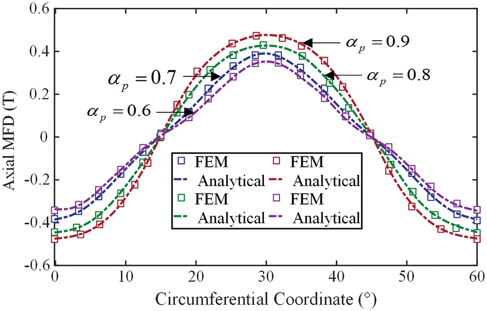
Figure 10: Axial MFD under variable pole-arc coefficients
Fig. 11 shows the simulation result of AEFD on copper plate through 3-D finite element simulation. The distribution of AEFD on the plane z = 0 is shown in Fig. 12, which shows a periodic variation along θ-direction. In each period, the force density varies within a fixed range, indicating that the rotation of the two discs does not affect the distribution of force density and force, ensuring that the equipment can operate stably. The distribution characteristics of AEFD are the same as MFD shown in Fig. 8, which can prove that AEFD is only related to MFD, i.e., the area where the PMs are located coincides with the area where AEFD is concentrated.
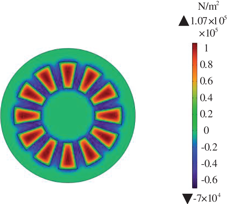
Figure 11: AEFD distribution on the surface of copper plate
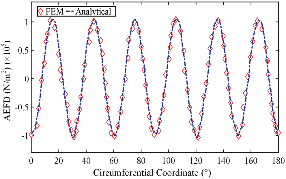
Figure 12: AEFD on the plane z = 0
4.3 Analysis of Torque Characteristic and Experimental Tests
To confirm the effectiveness of the proposed method, the demonstrations and comparisons are presented among analytical results, FEM, and experimental results. Experiments are performed on a 15 kW prototype equipped with the parameters shown in Table 1 and the test bench in Fig. 13.
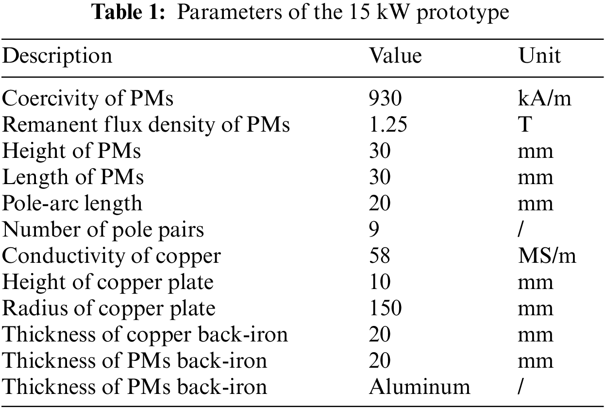
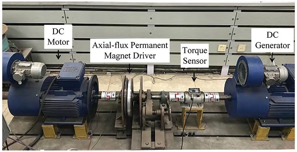
Figure 13: The test bench of APMD
The torque-slip speed characteristic curves calculated by the analytical method and 3-D finite element simulation for an air-gap length of 4 mm are shown in Fig. 14. The results obtained by both two methods are consistent with an error rate within 6%. The error between the analytical results and the finite element results in this paper is about 4% lower than the results before optimization in [27], which is almost the same as the error rate after optimization. In addition, since the model established in this paper is completely analytical and the scope of the computing domain is reasonably determined, the computation time is less than [27], and the requirements on device memory and CPU are lower.
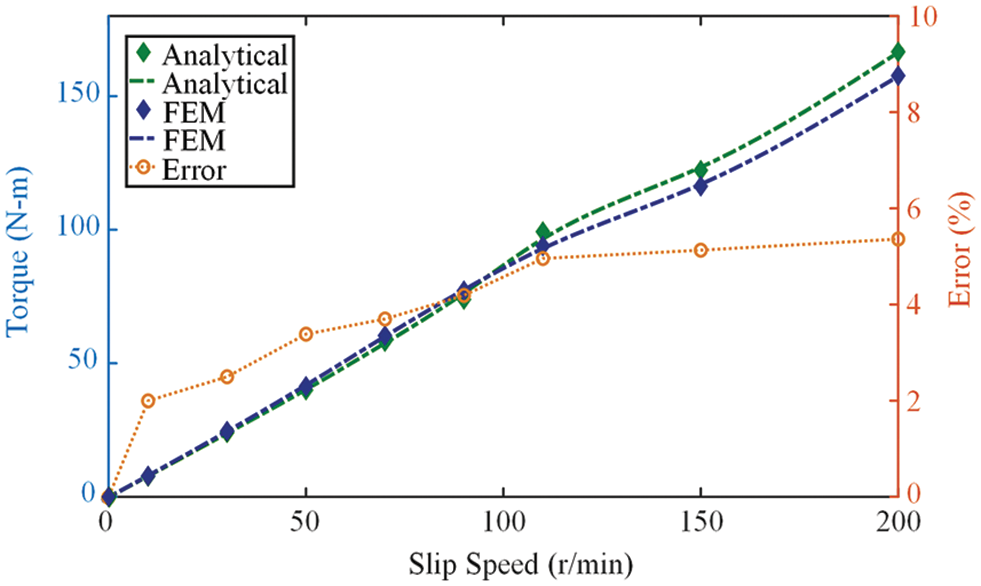
Figure 14: Torque-slip speed characteristics under 4 mm air-gap
To improve the convergence of the model, the open-loop problem is transformed into a closed-loop problem by setting a tenth of the outer radius of PM as the zero SMP. The details of the finite element simulation model are appropriately simplified in the modeling: the magnetization of magnetic materials is ignored, the partition meshing strategy is adopted, the key areas are encrypted, and the general solver is selected. These operations inevitably make the Jacobian coefficient of some grids exceed the limit, which not only improves the calculation efficiency and convergence of the model but also damages the fidelity and further manifests as a certain deviation from the analytical model. In addition, for a practical problem, most equations cannot be solved directly. It is necessary to simplify and transform the equations, set appropriate boundary conditions, and set initial values. These steps will also introduce errors between the results of finite element simulation and analytical calculation results. However, errors within a certain range are acceptable for practical engineering problems. The model built in this paper attempts to balance the computational efficiency and fidelity to improve the value of the model in engineering applications.
As studied in [27], the highly efficient working interval of APMD is usually concentrated in the region of low slip. Fig. 15 shows the torque output results of APMD operating with the air-gap thicknesses of 3 and 5 mm, respectively. The air-gap reluctance increases with the increase of thickness, which reduces the effective MFD in the air-gap. The transmission torque is reduced at the same slip speed, which is an important characteristic of APMD. When it is used as a governor, the output speed can be adjusted in practice by regulating the thickness of the air-gap.
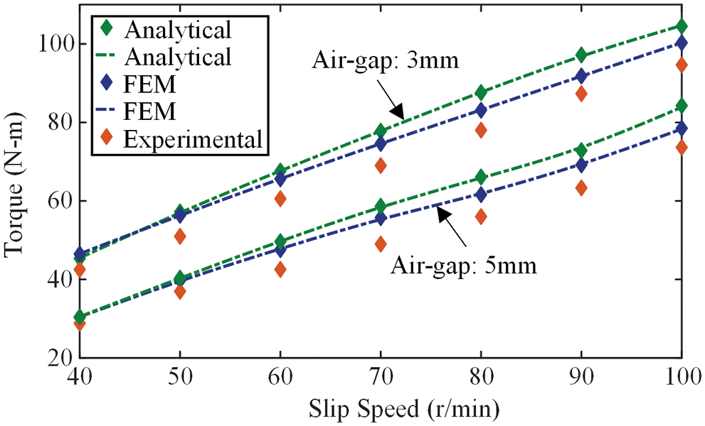
Figure 15: Torque-slip speed characteristics under 3 and 5 mm air-gap
From the above analysis, it can be easily concluded that APMD can adjust the output speed conveniently and is extremely inclusive of the forces on the drive shaft. This is an excellent quality that other mechanical connection devices lack, which is also one of the reasons why APMD is so popular in the transmission system.
APMD can effectively solve the harsh alignment problems of electric drive systems, however, there is a lack of independent and complete modeling theory. For a long time, many researchers have been modeling and analyzing APMD with reference to devices with similar characteristics such as motors and brakes, trying to predict the performance of APMD with higher accuracy and to improve the efficiency of the transmission system.
In this paper, the analytical models are established in 3-D cylindrical coordinates considering the inherent geometric properties of APMD. In order to balance the contradiction between the high accuracy of SVM and the difficulty of determining the parameters of the Bessel equation, the boundary conditions are simplified from the three directions of r, θ, and z, and the solutions of the governing equations are obtained in a relatively simple way. The range of the calculation domain is determined according to the domain truncation theory, which not only ensures the accuracy of the calculation results but also saves the calculation time and cost. After establishing the surface magnetic charge model of PMs in the r−θ plane and introducing the Fourier-Bessel series, the axial magnetization of sector-shaped PMs is expressed in an explicit algebraic form, rather than a complex series form. The model is clearly expressed by the design parameters of APMD, which possesses more distinct physical significance than the series expression in pure mathematical form. The parameters of the Bessel equation are determined, and the precise magnetic field analytical models of PMs and the air-gap are also given definitely. The distribution of MFD is accurately predicted and the model is fully analytical, so the electromagnetic torque can be calculated directly using MST. Based on 3-D finite element simulation, the influences of design parameters including the thickness of the air-gap, the inner diameter of PMs, and the pole-arc coefficient on axial MFD are studied, therefore, the accuracy of the analytical models is comprehensively verified. A 15 kW prototype is built and the torque-slip characteristics under different air-gap lengths are studied. The results show that the analytical calculation results are in good agreement with the finite element results and experimental results. The modeling method proposed in this paper can calculate the magnetic field distribution and electromagnetic torque accurately and rapidly and provides an important reference for the design and optimization of APMD.
Funding Statement: This work was supported by the National Natural Science Foundation of China under Grant [52077027] and Liaoning Province Science and Technology Major Project [No. 2020JH1/10100020].
Conflicts of Interest: The authors declare that they have no known competing financial interests or personal relationships that could have appeared to influence the work reported in this paper.
References
1. X. W. Yang, Y. G. Liu and L. Wang, “Nonlinear modeling of transmission performance for permanent magnet eddy current coupler,” Mathematical Problems in Engineering, vol. 2019, no. 10, pp. 1–14, 2019. [Google Scholar]
2. Y. B. Li, H. Y. Lin, H. Huang, C. Chen and H. Yang, “Analysis and performance evaluation of an efficient power-fed permanent magnet adjustable speed drive,” IEEE Transactions on Industrial Electronics, vol. 66, no. 1, pp. 784–794, 2019. [Google Scholar]
3. W. H. Li, D. Z. Wang, T. L. Tong, D. S. Kong, S. H. Wang et al., “A simple 3-D analytical modeling method and sensitivity analysis for the axial-flux permanent magnet eddy current coupler,” in Proc. ICoPESA, Singapore, pp. 77–82, 2022. [Google Scholar]
4. Y. B. Li, H. Y. Lin, Q. C. Tao, X. Q. Lu, H. Yang et al., “Analytical analysis of an adjustable-speed permanent magnet eddy-current coupling with a non-rotary mechanical flux adjuster,” IEEE Transactions on Magnetics, vol. 55, no. 6, pp. 1–5, 2019. [Google Scholar]
5. A. Raza, “Mathematical modelling of rotavirus disease through efficient methods,” Computers, Materials and Continua, vol. 72, no. 3, pp. 4727–4740, 2022. [Google Scholar]
6. I. Mahariq, “On the application of the spectral element method in electromagnetic problems involving domain decomposition,” Turkish Journal of Electrical Engineering & Computer Sciences, vol. 25, no. 2, pp. 1059–1069, 2017. [Google Scholar]
7. A. Raza, M. Rafiq, J. Awrejcewicz, N. Ahmed and M. Mohsin, “Stochastic analysis of nonlinear cancer disease model through virotherapy and computational methods,” Mathematics, vol. 10, no. 3, pp. 1–18, 2022. [Google Scholar]
8. A. Raza, Y. M. Chu, M. Y. Bajuri, A. Ahmadian, N. Ahmed et al., “Dynamical and nonstandard computational analysis of heroin epidemic model,” Results in Physics, vol. 34, no. 1, pp. 1–10, 2022. [Google Scholar]
9. A. Raza, J. Awrejcewicz, M. Rafiq, N. Ahmed, M. S. Ahsan et al., “Dynamical analysis and design of computational methods for nonlinear stochastic leprosy epidemic model,” Alexandria Engineering Journal, vol. 61, no. 10, pp. 8097–8111, 2022. [Google Scholar]
10. A. Raza, J. Awrejcewicz, M. Rafiq and M. Mohsin, “Breakdown of a nonlinear stochastic Nipah virus epidemic model through efficient numerical methods,” Entropy, vol. 23, no. 12, pp. 01–20, 2021. [Google Scholar]
11. J. H. J. Potgieter and M. J. Kamper, “Optimum design and comparison of slip permanent-magnet couplings with wind energy as case study application,” IEEE Transactions on Industry Applications, vol. 50, no. 5, pp. 3223–3234, 2014. [Google Scholar]
12. M. Rafiq, M. Naveed, Z. Khan, A. Raza, J. Awrejcewicz et al., “Modeling the spread of leishmaniasis disease via delayed analysis,” Alexandria Engineering Journal, vol. 61, no. 12, pp. 11197–11209, 2022. [Google Scholar]
13. A. Raza, M. Rafiq, J. Awrejcewicz, N. Ahmed and M. Mohsin, “Dynamical analysis of coronavirus disease with crowding effect, and vaccination: A study of third strain,” Nonlinear Dynamics, vol. 107, no. 4, pp. 3963–3982, 2022. [Google Scholar]
14. I. Mahariq and H. Kurt, “Strong field enhancement of resonance modes in dielectric microcylinders,” Journal of the Optical Society of America B, vol. 33, no. 4, pp. 656–662, 2016. [Google Scholar]
15. I. Mahariq, T. Abdeljawad, A. S. Karar, S. A. Alboon, H. Kurt et al., “Photonic nanojets and whispering gallery modes in smooth and corrugated micro-cylinders under point-source illumination,” Photonics, vol. 7, no. 3, pp. 1–11, 2020. [Google Scholar]
16. J. Ping, Y. Yue, M. Y. Jin, S. H. Fang, H. Y. Lin et al., “3-D analytical magnetic field analysis of axial flux permanent-magnet machine,” IEEE Transactions on Magnetics, vol. 50, no. 11, pp. 1–4, 2014. [Google Scholar]
17. Z. Mouton and M. J. Kamper, “Modeling and optimal design of an eddy current coupling for slip-synchronous permanent magnet wind generators,” IEEE Transactions on Industrial Electronics, vol. 61, no. 7, pp. 3367–3376, 2014. [Google Scholar]
18. J. Wang and J. G. Zhu, “A simple method for performance prediction of permanent magnet eddy current couplings using a new magnetic equivalent circuit model,” IEEE Transactions on Industrial Electronics, vol. 65, no. 3, pp. 2487–2495, 2018. [Google Scholar]
19. V. Aberoomand, M. Mirsalim and R. Fesharakifard, “Design optimization of double-sided permanent-magnet axial eddy-current couplers for use in dynamic applications,” IEEE Transactions on Energy Conversion, vol. 34, no. 2, pp. 909–920, 2019. [Google Scholar]
20. I. Mahariq and A. Erciyas, “A spectral element method for the solution of magnetostatic fields,” Turkish Journal of Electrical Engineering & Computer Sciences, vol. 25, no. 4, pp. 2922–2932, 2017. [Google Scholar]
21. I. Mahariq, M. Kuzuolu, I. H. Tarman and H. Kurt, “Photonic nanojet analysis by spectral element method,” IEEE Photonics Journal, vol. 6, no. 5, pp. 1–14, 2014. [Google Scholar]
22. I. Mahariq, H. I. Tarman and M. Kuzuoğlu, “On the accuracy of spectral element method in electromagnetic scattering problems,” International Journal of Computer Theory and Engineering, vol. 6, no. 6, pp. 495–499, 2014. [Google Scholar]
23. X. Dai, J. Y. Cao, Y. J. Long, Q. H. Liang, J. Q. Mo et al., “Analytical modeling of an eddy-current adjustable speed coupling system with a three-segment Halbach magnet array,” Electric Power Components and Systems, vol. 43, no. 17, pp. 1891–1901, 2015. [Google Scholar]
24. S. A. Hong, J. Y. Choi, S. M. Jang and K. H. Jung, “Torque analysis and experimental testing of axial flux permanent magnet couplings using analytical field calculations based on two polar coordinate systems,” IEEE Transactions on Magnetics, vol. 50, no. 11, pp. 1–4, 2014. [Google Scholar]
25. H. K. Yeo, H. J. Park, J. M. Seo, S. Y. Jung and J. S. Ro, “Electromagnetic and thermal analysis of a surface-mounted permanent-magnet motor with overhang structure,” IEEE Transactions on Magnetics, vol. 53, no. 6, pp. 1–4, 2017. [Google Scholar]
26. G. J. Zhu, Y. H. Zhu, W. M. Tong, X. Y. Han and J. G. Zhu, “Double-circulatory thermal analyses of a water-cooled permanent magnet motor based on a modified model,” IEEE Transactions on Magnetics, vol. 54, no. 3, pp. 1–4, 2018. [Google Scholar]
27. Z. Li, L. Yan, B. Y. Qu and K. Fu, “Analytical prediction and optimization of torque characteristic for flux-concentration cage-type eddy-current couplings with slotted conductor rotor topology,” International Journal of Applied Electromagnetics and Mechanics, vol. 62, no. 2, pp. 295–313, 2020. [Google Scholar]
Cite This Article
 Copyright © 2023 The Author(s). Published by Tech Science Press.
This work is licensed under a Creative Commons Attribution 4.0 International License , which permits unrestricted use, distribution, and reproduction in any medium, provided the original work is properly cited.
 Downloads
 Citation Tools