
 Submit a Paper
 Propose a Special lssue
 Open Access
ARTICLE

Zero-Index Metamaterial Superstrates UWB Antenna for Microwave Imaging Detection
1 Faculty of Electronic Engineering Technology, Universiti Malaysia Perlis, Pauh Putra Campus, 02600, Arau, Malaysia
2 Faculty of Electrical Engineering Technology, Universiti Malaysia Perlis, Pauh Putra Campus, 02600, Arau, Malaysia
3 Faculty of Mechanical and Manufacturing Engineering, Universiti Malaysia Pahang, 26600, Pekan, Malaysia
* Corresponding Author: Mohd Aminudin Jamlos. Email:
Computers, Materials & Continua 2023, 75(1), 277-292. https://doi.org/10.32604/cmc.2023.032840
Received 29 May 2022; Accepted 22 September 2022; Issue published 06 February 2023
 View Full Text
 Download PDF
Abstract
Metamaterials (MTM) can enhance the properties of microwaves and also exceed some limitations of devices used in technical practice. Note that the antenna is the element for realizing a microwave imaging (MWI) system since it is where signal transmission and absorption occur. Ultra-Wideband (UWB) antenna superstrates with MTM elements to ensure the signal transmitted from the antenna reaches the tumor and is absorbed by the same antenna. The lack of conventional head imaging techniques, for instance, Magnetic Resonance Imaging (MRI) and Computerized Tomography (CT)-scan, has been demonstrated in the paper focusing on the point of failure of these techniques for prompt diagnosis and portable systems. Furthermore, the importance of MWI has been addressed elaborately to portray its effectiveness and aptness for a primary tumor diagnosis. Other than that, MTM element designs have been discussed thoroughly based on their performances towards the contributions to the better image resolution of MWI with detailed reasonings. This paper proposes the novel design of a Zeroindex Split Ring Resonator (SRR) MTM element superstrate with a UWB antenna implemented in MWI systems for detecting tumor. The novel design of the MTM enables the realization of a high gain of a superstrate UWB antenna with the highest gain of 5.70 dB. Besides that, the MTM imitates the conduct of the zeroreflection phase on the resonance frequency, which does not exist. An antenna with an MTM unit is of a 7 × 4 and 10 × 5 Zero-index SRR MTM element that acts as a superstrate plane to the antenna. Apart from that, Rogers (RT5880) substrate material is employed to fabricate the designed MTM unit cell, with the following characteristics: 0.51 mm thickness, the loss tangent of 0.02, as well as the relative permittivity of 2.2, with Computer Simulation Technology (CST) performing the simulation and design. Both MTM unit cells of 7 × 4 and 10 × 5 attained 0° with respect to the reflection phase at the 2.70 GHz frequency band. The first design, MTM Antenna Design 1, consists of a 7 × 4 MTM unit cell that observed a rise of 5.70 dB with a return loss (S11) −20.007 dB at 2.70 GHz frequency. The second design, MTM Antenna Design 2, consists of 10 × 5 MTM unit cells that recorded a gain of 5.66 dB, having the return loss (S11) −19.734 dB at 2.70 GHz frequency. Comparing these two MTM elements superstrates with the antenna, one can notice that the 7 × 4 MTM element shape has a low number of the unit cell with high gain and is a better choice than the 10 × 5 MTM element in realizing MTM element superstrates antenna for MWI.Keywords
Artificial electromagnetic metamaterials (MTM) have become increasingly popular in recent years. Magnetic permeability, as well as electric permittivity, are properties that electromagnetic MTM can exhibit, according to the effective medium theory. Employing a metallic wire with negative permittivity created an artificially electrified plasma [1]. Other than that, MTM enables the design of various cellular designs utilizing various substrate materials, which opens up the possibilities to realize all potential material qualities [2–4]. Zero permittivity/permeability/index is a unique material parameter among the many uncommon material parameters offered by MTM, yielding many fascinating phenomena and uses [5,6], indicating that effective Zero-Index Metamaterial (ZIM) may boost uniform fields. Apart from that, the present research suggests that ZIM’s distinctive features may have opened up the latest possibilities for developing revolutionary high-gain antennas. For example, Zhou et al. [7] demonstrated that effective ZIM could enhance uniform fields.
An antenna transmits low-power microwave signals into tissues, resulting in attenuated, reflected, and absorbed signals. Note that active microwave imaging (MWI) uses backscattered signals, which are reflections caused by the propagation of signals from one medium to another, to produce microwave images. Active MWI will also be divided into tomography MWI and Ultra-Wideband (UWB) radar MWI. Moreover, the UWB radar MWI method was initially established to detect breast tumors [8]. An Ultra-Wideband (UWB) antenna with a wide operating frequency has been chosen as the detector due to a higher signal being transmitted through the tumor located inside the brain, resulting in a clearer and sharper image of the tumor detected. A low range frequency of 2.7 GHz (< 3 GHz) has been set up as the operating frequency due to the requirement of a longer signal to have adequate penetration in order for the signal to reach the tumor within the human brain. Progressively, quite a few approaches and configurations have been invented and modified to be aligned with advanced technology. This thesis generally applied similar principles of the technique with some changes to suit tumor detection within the brain. To date, there are sensitive technologies for head imaging like Magnetic Resonance Imaging (MRI) as well as Computerized Tomography (CT) scans for the primary verdict concerning brain tumors. These techniques are bulky, immobile, fixed in arrangement, expensive, time-consuming, and cannot be created and offered in a geographical region. As these techniques involve heavy machinery, they cannot be carried by the paraprofessional groups to the patient. In these cases, the primary assessment of the patient could be a crucial medical emergency. Consequently, researchers have projected MWI as another on-site detection system for brain tumor diagnosis. Among the other advantages of MWI embodying non-invasive are the potential to focus energy, a wide range of frequencies, a range of simulation tools, and a less costly and portable option compared to MRI and CT scans, which are enclosed within the advantages of MWI [9,10]. Other than that, MWI with accomplishment enforced in breast tumor detection is reviewed in [11,12] and more recently in brain tumor detection [13,14].
In MWI, lower frequency has contributed to higher penetration depth, whereas higher frequency has contributed to better image resolution [15]. Therefore, the performance of the MTM superstrates with the antenna involved in the MWI system has a vital role in better imaging. Traditional materials cannot be used to create an antenna with innovative characteristics since MTM have peculiar qualities. The MTM antenna is made up of one or more layers of MTM that are added to the antenna’s configuration or utilized as substrates to enhance its performance [16]. The selection of an MTM’s structure and application technique varies based on the antenna’s intended use. ZIM, for instance, benefits from a straightforward design and compact design. Moreover, it may enhance the antenna performances by superstrating together and giving a higher gain performance that is important to MWI detection to obtain better imaging of the tumor image.
MTMs are artificial materials whose qualities can be deduced from their component parts and their main purpose. For hundreds of years, researchers have been intensely interested in MTMs with nearly zero indices of refraction. Typically, a ZIM is meant to function as a transmitter or a reflector, depending on the limits of the significant flaw included inside the fake design [17]. According to Snell’s law, it is regarded as an incident ray having grazing incidence that originates from a source within the ZIM and strikes a ZIM interface. A beam with a nearly zero index in the medium will be refracted almost in a normal direction. Note that the normal direction is closer, the lower the optical index. Using a monopole source implanted in ZIM to confine the radiated energy to a narrow solid angle, Enoch et al. [18] pioneered in producing highly directed radiation. On the other hand, Zhou et al. [7] suggested a left-handed MTM as a substrate for designing directed radiation in response to Enoch’s work. The zero-index frequency may be modified to the appropriate specification to generate directional emission by manipulating the structure’s geometry. Additionally, studies of additional directional radiation-related works using ZIM were conducted. Nevertheless, the directive antennas relying on ZIM in the earlier references only work at a narrowband frequency or a single frequency [7]. ZIM frequently uses the boundaries of the significant flaw installed inside the fake building to function as a reflector or transmitter. An intriguing category of MTM known as zero-index media includes structures with a sufficient condition of zero refraction (at the frequency of interest). In the event that they are not, they will, in theory, be included as MTMs. It has been claimed that zero-index materials frequently exhibit the propensity to transform bending wavefronts into plane ones, style postpone lines, and restrict the far-field example of an antenna implanted within the medium. Apart from that, epsilon-close-to-zero (ENZ) materials have also recently been known to improve the specific waveguides’ productivity and reduce the reflection coefficient at a crossing point or curve [19]. Generally speaking, a ZIM is not coordinated to free space until the penetrability and penetrability are simultaneously zero, combined with regularly high reflectance. When a real component of the texture is electrically weak, a significant exception to the existing rule may appear. Investigate the possibility of planning indexless media tuned to free space since this restriction may be too severe and unavoidably implemented. A material having a permittivity on the cusp of zero that is unattractive is easily accessible. Hence, this work studies UWB antenna superstrates with ZIM elements as an inspiration from [18]. Simulations and measurements are used to examine the performance of the ZIM antennas. It is shown that the suggested ZIM antennas’ gain at biomedical frequencies can be higher than that of antennas without the ZIM.
This paper is written in the following sequence: starting with an introduction, Zero-Index Split Ring Resonator Metamaterial (MTM) Element Design, Zero-Index Split Ring Resonator Metamaterial (MTM). Element Performances, Zero-Index Split Ring Resonator Metamaterial (MTM) Element with UWB. Antenna Performances, Zero-Index Split Ring Resonator Metamaterial (MTM) Element with UWB Antenna for Microwave Imaging Detection Performances and ending by a conclusion.
2 Zero-Index Split Ring Resonator Metamaterial (MTM) Element Design
The suggested antenna design architecture is initiated by the metamaterial (MTM) unit cell. A unit cell design with a resonance characteristic in the frequency range of 3.1 to 10.6 GHz is what is desired. For designing MTM structures, a number of well-known techniques are employed, for instance, Split Ring Resonators (SRR) [15,20]. The first unit cell in this study is constructed on an SRR structure. Moreover, the SRR has four loops, each of which has slots at its opposing ends. Each loop is a smaller loop inside a larger one [16]. A magnetically resonant structure, like an SRR, responds to a perpendicular magnetic field in a way that can result in negative permeability. The addition of gaps (splits) to the ring also introduces capacitance, allowing for adjustment with respect to the structure’s resonant characteristic. Rectangular and SRR modifications to the initial unit cell are demonstrated in Fig. 1. Apart from that, the change involves closing the outer ring’s loop, which lowers the SRR’s series capacitance. Additionally, by closing the outer ring, the coupling between the inner and outer rings is improved, resulting in a broad backwards-wave passband [15]. A Rogers (RT5880) substrate having a 2.7 dielectric constant and a 0.51 mm thickness is used to print the unit cell. Thus, Table 1 summarizes the unit cell design specifications.
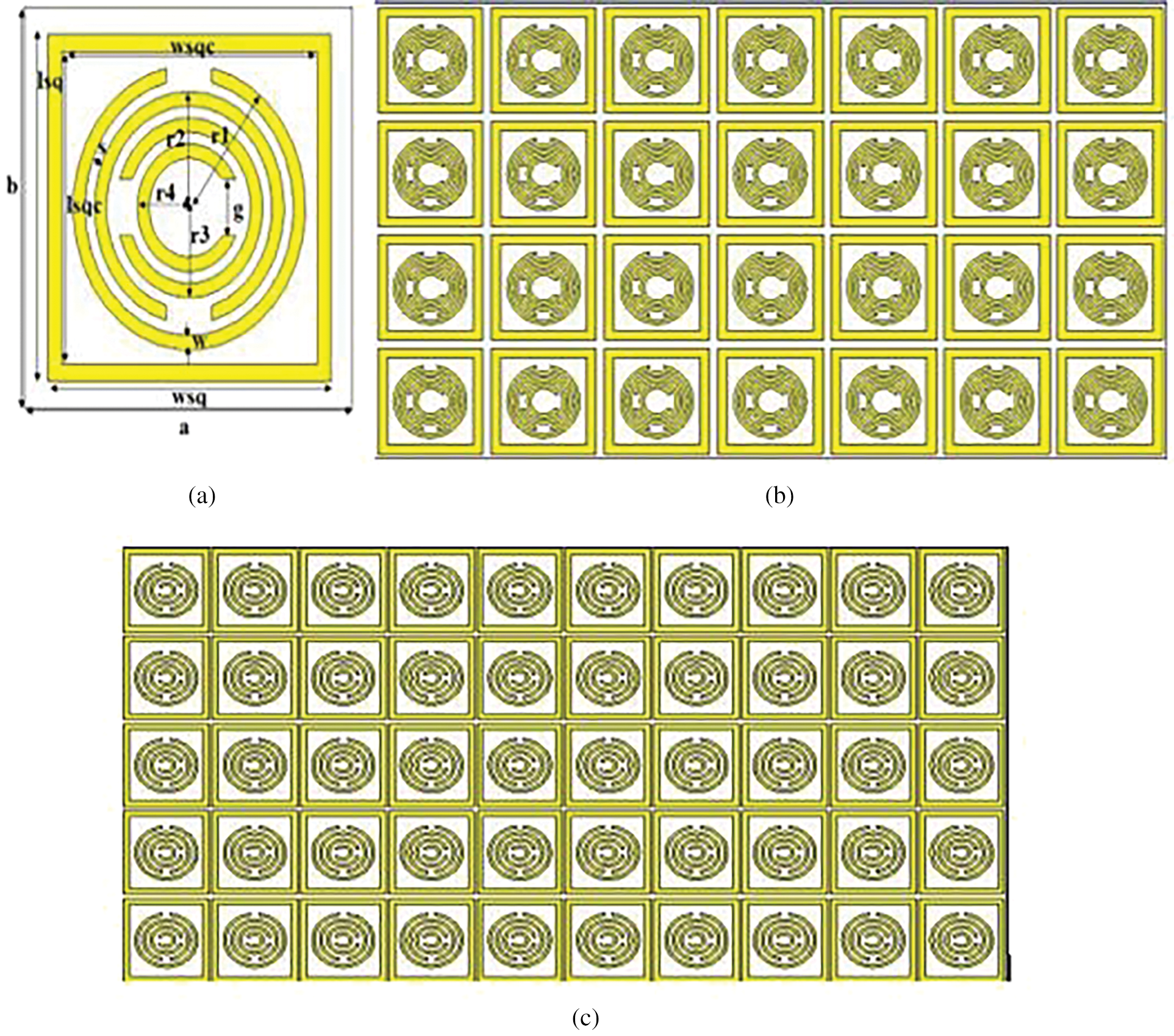
Figure 1: (a) Geometry of proposed front view of Metamaterial (MTM) Unit Cell, (b) Simulated MTM 7 × 4 unit cell Plane, and (c) Simulated MTM 10 × 5 unit cell Plane
There are six layers used in the design to form the overall structure of the MTM antenna. First, the bottom-most layer of the coaxial feeding embedded with a 0.035 mm-thick copper foil is placed in the ground plane. Subsequently, a 1.6 mm-thick Taconic substrate is placed above the next layer, while the graphene circular patch antenna is used as the patch antenna layer. Finally, the MTM unit cell array is embedded as a superstrate with the antenna, making the overall thickness of this antenna 21.215 mm, including the height of the superstrate, as portrayed in Fig. 2.
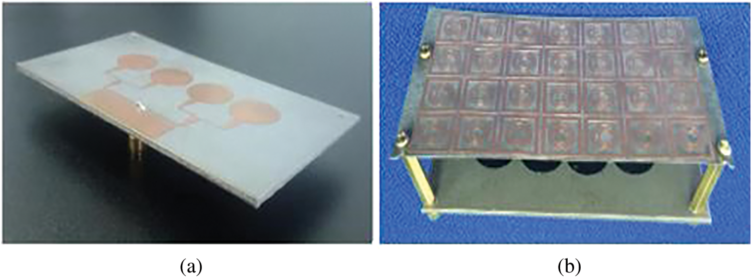
Figure 2: The fabricated suggested Metamaterial (MTM) antenna (a) antenna superstrates with no MTM plane (b) antenna superstrates with 7 × 4 MTM plane (c) antenna superstrates having 10 × 5 MTM plane
3 Zero-Index Split Ring Resonator Metamaterial (MTM) Element Performances
Employing Computer Simulation Technology (CST) software, the metamaterial (MTM) unit cell was simulated in the context of the finite difference frequency domain (FDFD) method of determining the Sparameter. Moreover, the test’s design was positioned between two waveguide terminals located at the bottom and top of the z-axis correspondingly. Therefore, along the z-axis, an electromagnetic wave was energized. Apart from that, the dividers on the other side of the x-axis were also applied, together with a perfectly direct electrical limit condition. In this case, the dividers opposing the y-axis were also applied, along with an impeccably leading attractive limit condition. This MTM structure is modelled using a frequency-domain solver to separate the refractive index (nr), effective permittivity (εr), and permeability (μr), constitutive factors from S21 and S11. The parametric investigation of the MTM unit cell design for the two sizes with respect to the proposed MTM plane structure is shown in Fig. 3, employing the CST software. In terms of the phase of reflection, its effectiveness can be seen. At the 2.70 GHz frequency range, the MTM 7 × 4-unit cells and 10 × 5-unit cells with dimensions 110 mm2 × 65 mm2 achieved a reflection phase of 0°.
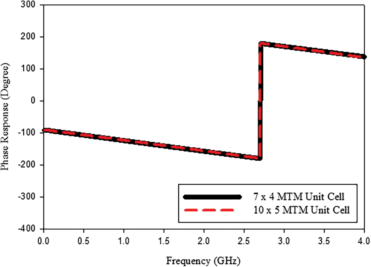
Figure 3: Phase Response size of MTM Unit Cell
As stated, prior, distinctive, or unique capabilities can be acquired directly using CST software. The obtained MTM 7 × 4-unit cells and 10 × 5-unit cells’ real and imaginary values for the dielectric constant, permeability (μ), nr, and wave impedance are shown in Figs. 4a–4d. Other than that, Niels-Weld techniques were utilized in the comparative study of MTM 7 × 4-unit cells and 10 × 5-unit cells to calculate the true parameters of permittivity (ε), permeability, nr, and wave impedance.
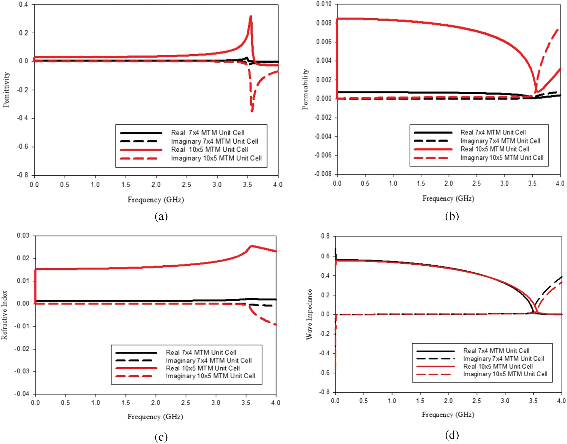
Figure 4: MTM 7 × 4-unit cells and 10 × 5-unit cells showed findings of (a) the permittivity, (b) the permeability, (c) the refractive index and (d) the wave impedance
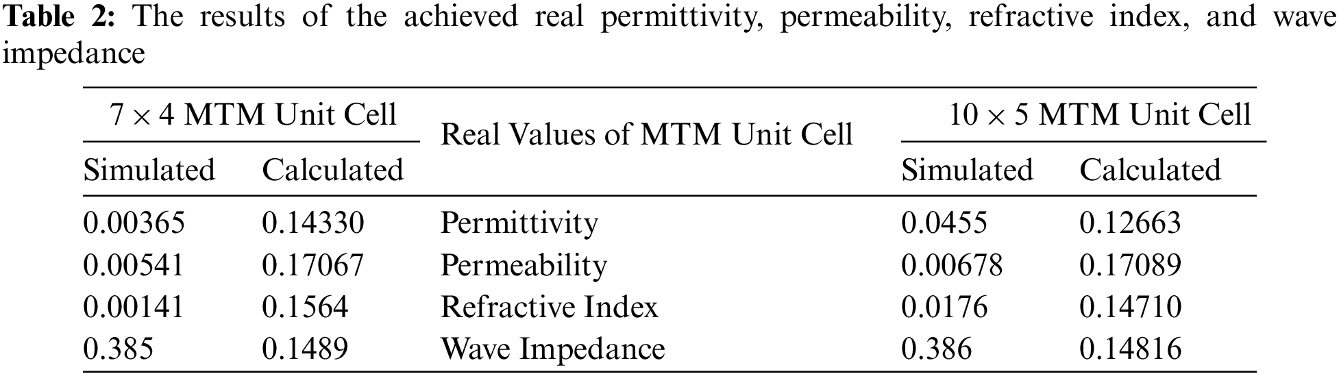
Coefficients of reflection and transmission are units in a fancy quantitative relation. Therefore, this advanced quantitative relation is divided into real and imaginary sections in order to analyze the zero-index features of ε and the permeability of the suggested MTM structure. The condition of the positive real component of permeability and ε, according to the MTM theory, is targeted at the suggested MTM design. Therefore, it can be seen from the feature’s plots that the ε and permeability findings for the proposed structure are close to zero at the on-point. The actual part of ε and permeability is portrayed in Figs. 4a and 4b. Hence, at 2.70 GHz frequency, the real part of ε and permeability’s positive values are near zero. Thus, at 2.70 GHz, the suggested Zero-Index MTM structure shows almost zero consequences of refraction. In Table 2, which was directly taken from CST software, are the actual ε, permeability, nr, and wave impedance that were attained. Based on Table 2, simulated and calculated results show good agreement. The outcome showed that for frequency bands of MTM 7 × 4-unit cells and 10 × 5-unit cells, the realized actual ε, permeability, nr, and wave impedance were extremely close to zero.
4 Zero-Index Split Ring Resonator Metamaterial (MTM) Elements with Ultra-Wideband Antenna Performances
The performance of some antennas with and without metamaterial elements in terms of gain is illustrated in Table 3 [19,21–27]

Figs. 5 and 6 display the simulation findings with respect to the reflection coefficient, S11, which is lower than −10 dB. The proposed antenna’s operating frequency of 2.70 GHz, which met the requirements for biomedical applications, is evidently shown in the figure. Since 90% of the signals are effectively transmitted, and only 10% are reflected, a reflection coefficient lower than −10 dB is utilized [28]. Additionally, a lower reflection coefficient is achieved using the partial ground approach and additional parasitic components. The MTM antenna having 7 × 4 and 10 × 5 elements are shown in Figs 5 and 6. The MTM antenna measures 110 mm × 65 mm in size. The port provides an impedance of 50 Ω in this case. The EM solver Computer Simulation Technology (CST) is used to simulate the MTM antenna structure.
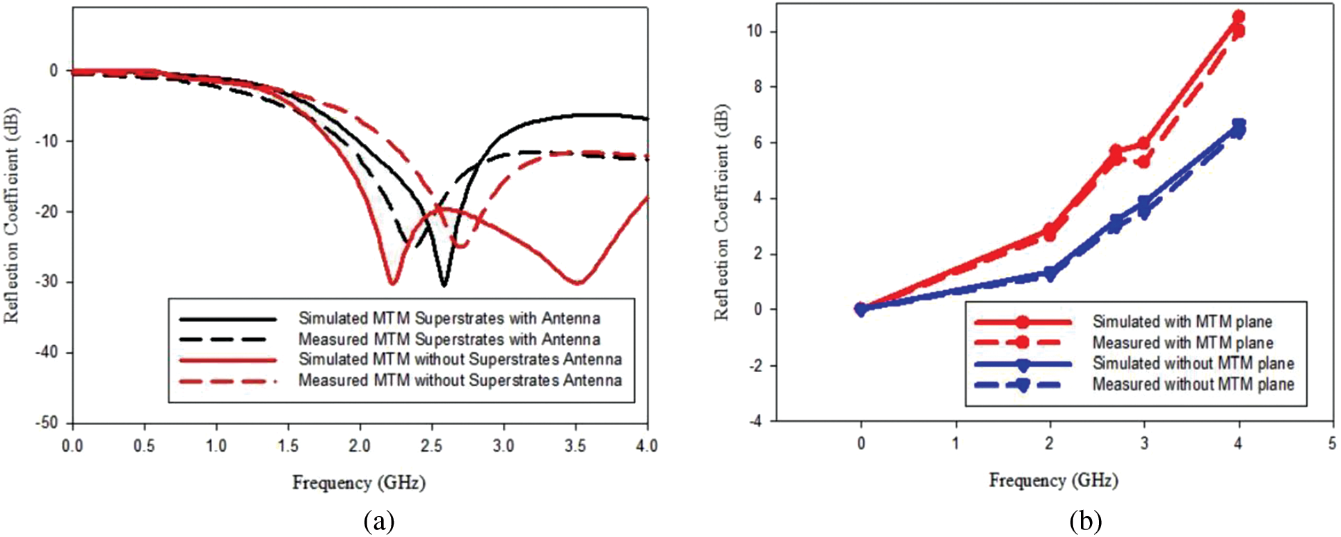
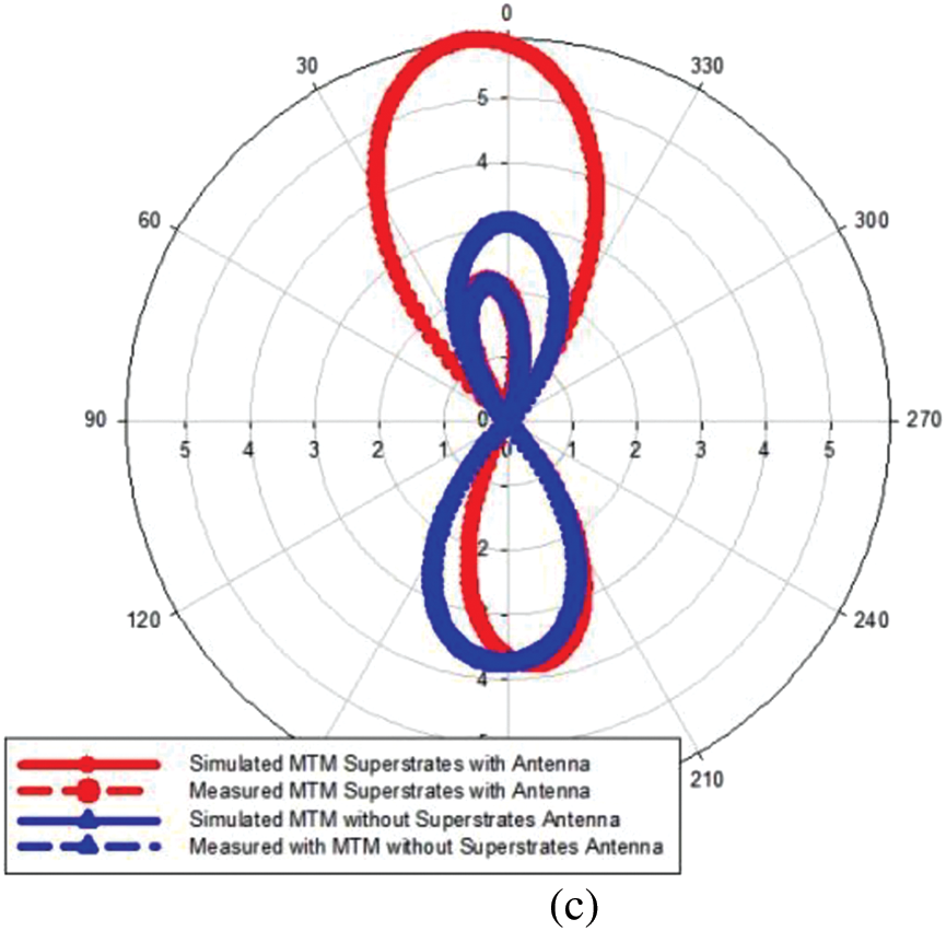
Figure 5: Simulated and measured 7 × 4 MTM Element Superstrates with and without Antenna (a) S11 result (b) gain result (c) radiation pattern
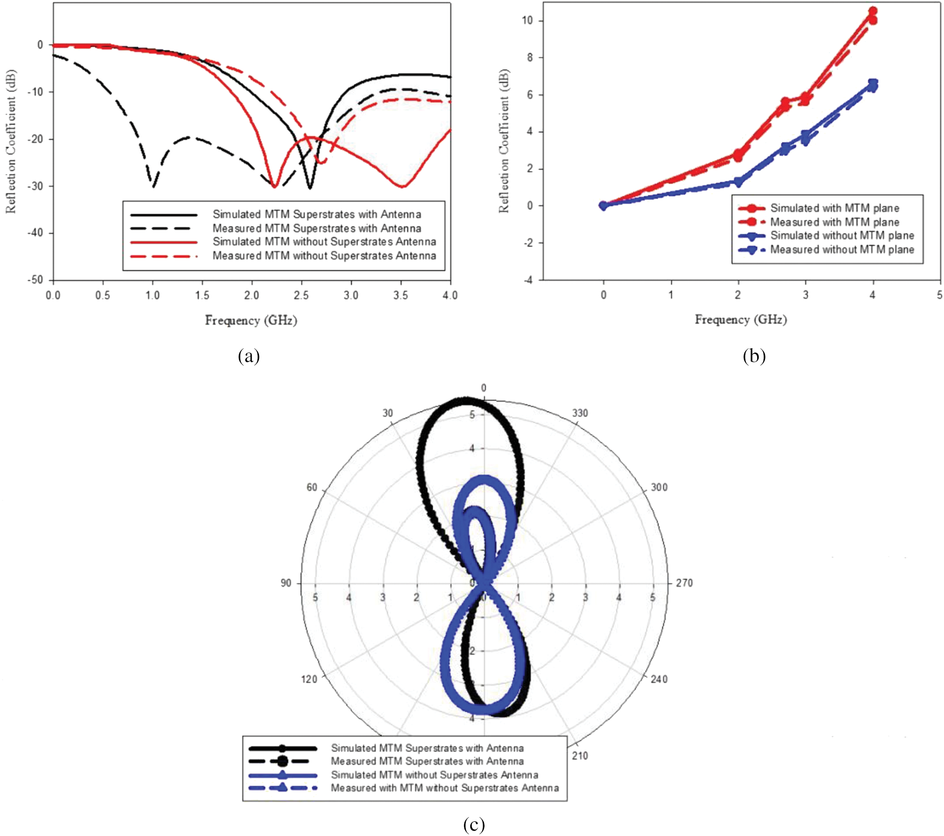
Figure 6: Simulated and measured 10 × 5 MTM Element Superstrates with and without Antenna (a) S11 result (b) gain result (c) radiation pattern
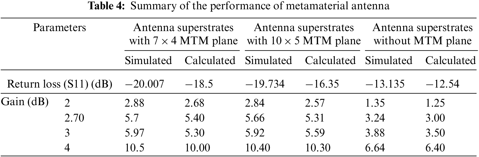
Upon associating the two MTM plane superstrates with the antenna, one can notice that the 7 × 4 MTM plane shape has a low number of unit cells with high gain and is a better choice than the 10 × 5 MTM plane, as shown in Table 4. Using confocal microwave imaging (MWI), the exceptional performance of the MTM antenna allowed for tumor recognition. With gains of up to 14.5 dB and a remarkably compact 90 mm × 45 mm form, it runs between 1.2 and 10.8 GHz. In order to test the system’s functionality, a head phantom that was built in-house is also cast-off for experimentation. The resultant image quality was also greatly enhanced by an Ultra-Wideband (UWB) confocal MWI algorithm utilized for image processing.
In this work, Zero-Index Split Ring Resonator MTM (SRR MTM) element superstrates with a UWB antenna are investigated. According to the previous research similar to the research project, for instance, the microstrip patch antenna gain’s Zero-Index Metamaterial (ZIM) superstrate, the electromagnetic parameters were investigated, and it was discovered that zero refraction happened at 9.908 to 11.1 GHz. Subsequently, anisotropic ZIM was loaded on top of the Vivaldi antenna with an 8.75 GHz resonance frequency. The previous research’s optimal gain demonstrated 2.6 dB and 4.23 dB. Moreover, the findings indicate that the energy radiated by the Zero-Index SRR MTM element superstrates with the UWB antenna becomes more concentrated, resulting in a higher gain obtained. Significantly, the UWB superstrates with Zero-Index SRR MTM elements are materialized. Otherwise, it is also anticipated that the suggested research MTM antenna may be implemented in the biomedical application area depending on the suitable operating frequency, which is in the range of 0.5–3.0 GHz.
5 Zero-Index Split Ring Resonator Metamaterial (MTM) Element with Ultra-Wideband Antenna for Microwave Imaging Detection Performances
A graph for the same cycle of signals in the frequency domain as well as the time domain is shown in Fig. 7a. Negative data values represent the frequency domain. In the meantime, a positive data value was captured in the temporal domain. Moreover, the frequency domain data must be transformed into the time domain since the confocal algorithm needs a round-trip time to create images. In contrast, Fig. 7b depicts a smooth time domain signal that has undergone the Inverse Fast Fourier transform (IFFT) procedure in order to become the original nonsmoothed signal. High and low spike forms are connected to the nonsmoothed signal. In comparison, the spline curve line indicates a smooth signal. For the purpose of detecting microwave brain tumours, the smoothed signal is essential for producing high spatial resolution images.
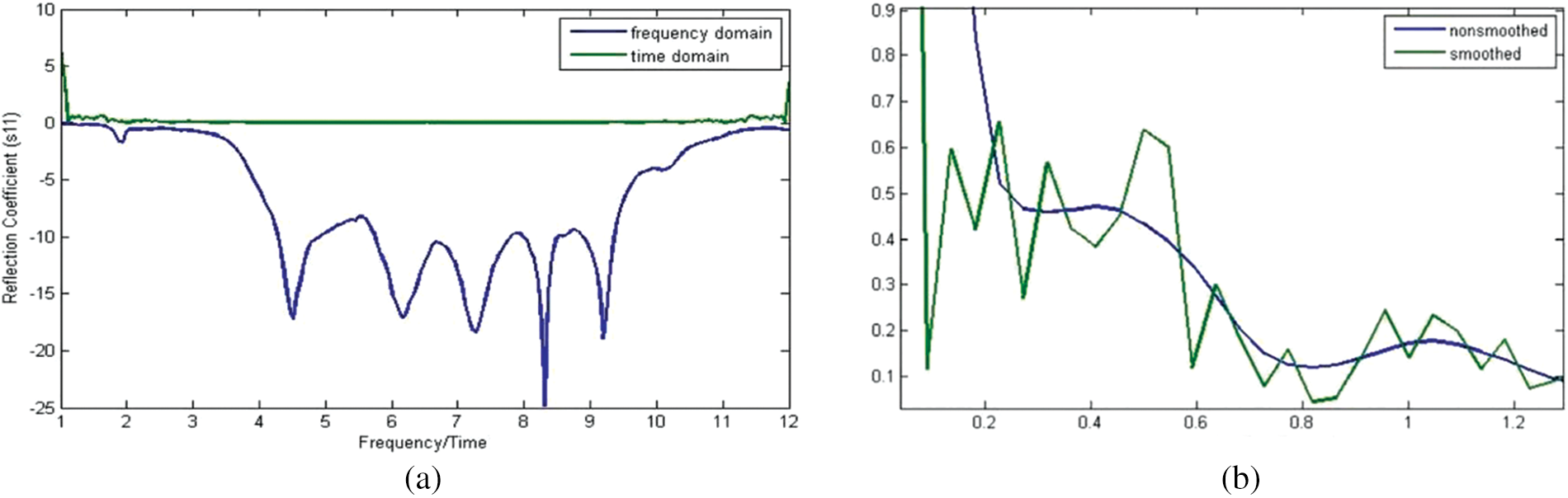
Figure 7: (a) The graph represents the time domain and frequency domain with respect to the same cycle of signals. (b) Smooth signal with respect to the time domain after undergoing the IFFT process towards the original nonsmoothed signal
The measurement setup concerning brain tumour detection utilizing microwave radar imaging techniques is shown in Fig. 8. It comprises a human head phantom having a tumor, an Ultra-Wideband (UWB) sensor, and a Vector Network Analyzer (VNA). Note that measurements are conducted in anechoic chambers to remove any extraneous signals that can interfere with the intended signals during the whole data collection procedure.
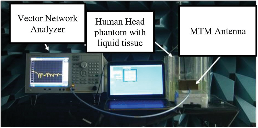
Figure 8: Measurement setup for microwave imaging
The multilayer human head phantom was positioned 10 mm from the UWB sensor in the ideal location for maximum signal penetration. To determine the difference in the scattering parameter value, the sensor radiated the signal in two distinct scenarios—one with a tumour present and the other without—at the human head phantom. In order to cover the whole one-sided phantom area, as illustrated in Fig. 9, in which the tumour is placed at position 5, the sensor radiated the signal toward nine separate locations. Tumor-containing and tumor-free data are subtracted from one another, and the resulting difference is processed to develop the desired image. Fig. 10 depicts the data generation and image construction flowchart for the UWB confocal algorithm. The Matrix Laboratory (MATLAB) software is employed to process the data produced by a confocal microwave imaging (MWI) algorithm.
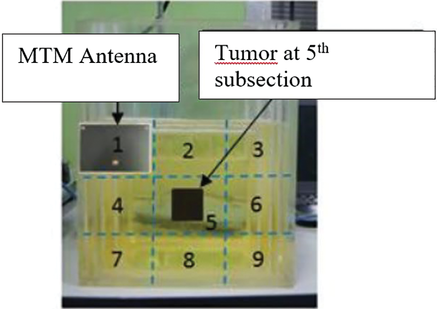
Figure 9: Scanning subsections on the human head phantom
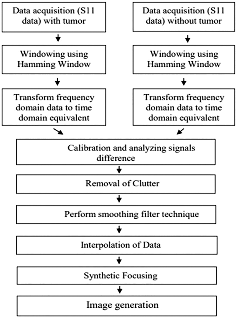
Figure 10: Flow chart of the upgraded delay and sum algorithm concerning data generation and image construction
Averaging and interpolation steps have been used in the process to produce a better and more distinct image for the algorithm. Additionally, averaging has the effect of removing clutters brought on by prevailing reflections from the surroundings, tools, and antennae. Theoretically speaking, interpolation is a technique for creating new data points that fall inside the range of a discrete existing data points’ set. In the meantime, interpolation, specifically for imaging, helps fill the empty element between the adjacent pixels via assumption depending on that specific adjacent pixels’ value [29–31].
Fig. 11 displays the images created by the UWB confocal algorithm and the original algorithm without and with tumor, correspondingly. The images were clearer and sharper, and areas with rising pixel intensity showed how effective the new delay and sum algorithm is. The strongest scattering region in the image, which produces the highest color intensity (reddish-orange spot), is the tumor. This is related to the tumor visible in the human head phantom.
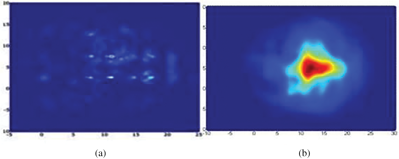
Figure 11: (a) Resulted in the image without tumor; (b) with tumor
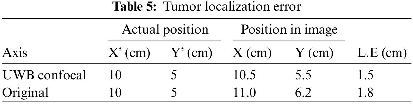
The efficiency of the improved confocal MWI algorithm is then assessed through the localization error analysis. These errors are carried out based on their distance from the reallocation of the tumour because the literature does not specify any minimum acceptable values for them. This is summarized in Table 5 for both the original algorithm as well as the UWB confocal. Compared to the original algorithm’s 1.8 cm error, the upgraded algorithm’s error was 1.5 cm.
A metamaterial (MTM) antenna has been proposed for microwave imaging (MWI) in this paper. While magnetic MTM has near-zero permeability, Zero-Index Metamaterial (ZIM) or double-positive media have near-zero permittivity (ε) for the electric MTM. The prototype has achieved a compact design also with an operational frequency range of 0 to 4.0 GHz with 7 × 4 MTM unit cell superstrates with the antenna. Note that the overall dimension concerning the MTM antenna is 110 mm × 65 mm. In order to locate a tumour utilizing confocal MWI on a human brain phantom, a high-performance ZIM superstrate with an antenna is demonstrated. Compared to a ZIM-less antenna, it delivered substantial gains. Other than that, experimental validation of this system’s functionality is performed using a head phantom created in-house. The resulting image quality was successfully enhanced using an image processing algorithm for UltraWideband (UWB) confocal MWI. Research on this system in the broader experimental MTM region and with many tumors is one of the proposed future projects.
Acknowledgement: This work was funded by the Fundamental Research Grant Scheme (FRGS/1/2018/ICT06/UNIMAP/02/1) of the Ministry of Higher Education of Malaysia.
Funding Statement: The authors received no specific funding for this study.
Conflicts of Interest: The authors declare that they have no conflicts of interest to report regarding the present study.
References
1. J. B. Pendry, A. J. Holden, D. J. Robbins and W. J. Stewart, “Magnetism from conductors and enhanced nonlinear phenomena,” IEEE Transactions on Microwave Theory and Techniques, vol. 47, no. 11, pp. 2075–2084, 1999. [Google Scholar]
2. J. Zhou, L. Zhang, G. Tuttle, T. Koschny and C. M. Soukoulis, “Negative index materials using simple short wire pairs.,” Physical Review B-Condensed Matter and Materials Physics, vol. 73, no. 4, pp. 041101, 2006. [Google Scholar]
3. A. T. Devapriya and S. Robinson, “Investigation on metamaterial antenna for terahertz applications,” Journal of Microwaves, Optoelectronics and Electromagnetic Applications, vol. 18, no. 3, pp. 377–389, 2019. [Google Scholar]
4. K. Zhang, P. Jack Soh and S. Yan, “Meta-wearable antennas-A review of metamaterial based antennas in wireless body area networks,” Materials, vol. 14, no. 1, pp. 1–20, 2021. [Google Scholar]
5. Q. Hou, H. Tang, Y. Liu and X. Zhao, “Dual-frequency and broadband circular patch antennas with a monopole-type pattern based on epsilon-negative transmission line,” IEEE Antennas and Wireless Propagation Letters, vol. 11, pp. 442–445, 2012. [Google Scholar]
6. Y. Yao, X. Wang and J. Yu, “Multiband planar monopole antenna for LTE MIMO systems,” International Journal of Antennas and Propagation, vol. 2012, 2012. [Google Scholar]
7. H. Zhou, Z. Pei, S. Qu, Z. Song, W. Jiafu et al., “A novel high-directivity microstrip patch antenna based on zero-index metamaterial,” IEEE Antennas and Wireless Propagation Letters, vol. 8, pp. 538–541, 2009. [Google Scholar]
8. S. C. Hagness, A. Taftore and J. E. Bridges, “Erratum: Correction to two-dimensional fdtd analysis of a pulsed microwave confocal system for breast cancer detection: Fixed-focus and antenna-array sensors,” IEEE Transactions on Biomedical Engineering, vol. 46, no. 3, pp. 364, 1999. [Google Scholar]
9. A. M. Abbosh, A. Zamani and A. T. Mobashsher, “Real-time frequency-based multistatic microwave imaging for medical applications (Invited),” in 2015 IEEE MTT-S Int. Microwave Workshop Series on RF and Wireless Technologies for Biomedical and Healthcare Applications, IMWS-BIO 2015-Proc., Taipei, Taiwan, pp. 127–128, 2015. [Google Scholar]
10. S. Sasada, N. Masumoto, H. Song, E. Akiko, K. Takayuki et al., “Microwave breast imaging using rotational bistatic impulse radar for the detection of breast cancer: Protocol for a prospective diagnostic study,” JMIR Research Protocols, vol. 9, no. 10, pp. 17524, 2020. [Google Scholar]
11. M. Z. Mahmud, M. T. Islam, N. Misran, A. F. Almutairi and M. Cho, “Ultra-wideband (UWB) antenna sensor based microwave breast imaging: A review,” Sensors (Switzerland), vol. 18, no. 9, pp. 2951, 2018. [Google Scholar]
12. N. Koma’rudin, Z. A. Zakaria, P. J. Soh, H. Lago, H. Alsariera et al., “A review of recent microwave breast imaging,” International Journal on Communications Antenna and Propagation, vol. 10, no. 4, pp. 257–267, 2020. [Google Scholar]
13. B. Velan, L. Jegan Antony Marcilin, I. Rexiline Sheeba, S. Mani and M. S. Sanju, “Design of microwave wideband antenna for brain tumor imaging applications,” in Proc. -Int. Conf. on Artificial Intelligence and Smart Systems, ICAIS 2021, Coimbatore, Tamilnadu, pp. 906–910, 2021. [Google Scholar]
14. H. R. Sholeh, M. Rizkinia and B. Basari, “Design of microwave-based brain tumor detection framework with the development of sparse and low-rank compressive sensing image reconstruction,” International Journal of Technology, vol. 11, no. 5, pp. 984–994, 2020. [Google Scholar]
15. M. M. Islam, M. T. Islam, M. R. I. Faruque, M. Samsuzzaman, N. Misran et al., “Microwave imaging sensor using compact metamaterial UWB antenna with a high correlation factor,” Materials, vol. 8, no. 8, pp. 4631–4651, 2015. [Google Scholar]
16. M. M. Islam, M. T. Islam, M. Samsuzzaman, M. R. I. Faruque, N. Misran et al., “A miniaturized antenna with negative index metamaterial based on modified SRR and CLS unit cell for UWB microwave imaging applications,” Materials, vol. 8, no. 2, pp. 392–407, 2015. [Google Scholar]
17. T. T. Koutserimpas and R. Fleury, “Zero refractive index in time-floquet acoustic metamaterials,” Journal of Applied Physics, vol. 123, no. 9, pp. 091709, 2018. [Google Scholar]
18. S. Enoch, G. Tayeb, P. Sabouroux, N. Guérin and P. Vincent, “A metamaterial for directive emission,” Physical Review Letters, vol. 89, no. 21, pp. 213902, 2002. [Google Scholar]
19. H. Liu, S. Lei, X. Shi and L. Li, “Study of antenna superstrates using metamaterials for directivity enhancement based on fabry-perot resonant cavity,” International Journal of Antennas and Propagation, vol. 2013, 2013. [Google Scholar]
20. S. E. Mendhe and Y. P. Kosta, “Metamaterial properties and applications,” International Journal of Information Technology and Knowledge Management, vol. 4, no. 1, pp. 85–89, 2011. [Google Scholar]
21. W. Bingheng, J. Yicai and F. Guangyou, “Design and measurement of compact tapered slot antenna for UWB microwave imaging radar,” in ICEMI 2009-Proc. of 9th Int. Conf. on Electronic Measurement and Instruments, Beijing, China, pp. 2226–2229, 2009. [Google Scholar]
22. S. Adnan, R. A. Abd-Alhameed, H. I. Hraga, I. T. E. Elfergani, J. M. Noras et al., “Microstrip antenna for microwave imaging application,” in Progress in Electromagnetics Research Symp., Marrakesh, Morocco, pp. 431–434, 2011. [Google Scholar]
23. M. A. Jamlos, W. A. Mustafa and N. Husna, “Ultra-wideband confocal microwave imaging for brain tumor detection,” IOP Conference Series: Materials Science and Engineering, vol. 557, pp. 012002, 2019. [Google Scholar]
24. M. T. Islam, M. M. Islam, M. Samsuzzaman, M. R. I. Faruque and N. Misran, “A negative index metamaterial-inspired UWB antenna with an integration of complementary srr and cls unit cells for microwave imaging sensor applications,” Sensors (Switzerland), vol. 15, no. 5, pp. 11601–11627, 2015. [Google Scholar]
25. M. T. Islam, M. T. Islam, M. Samsuzzaman, H. Arshad and H. Rmili, “Metamaterial loaded nine high gain vivaldi antennas array for microwave breast imaging application,” IEEE Access, vol. 8, pp. 227678–227689, 2020. [Google Scholar]
26. M. Anto Bennet, R. Himaya, K. Deepa, V. Divya and V. Aarthi, “Design and implementation of rectangular microstrip patch antennas for biomedical applications,” International Journal of Recent Technology and Engineering, vol. 7, no. 6, pp. 170–176, 2019. [Google Scholar]
27. M. Bhaskar, Z. Akhter, S. L. Gupta and M. J. Akhtar, “Design of anisotropic zero-index metamaterial loaded tapered slot vivaldi antenna for microwave imaging,” in IEEE Antennas and Propagation Society, AP-S Int. Symp. (Digest), Memphis, Tennessee, USA, pp. 1594–1595, 2014. [Google Scholar]
28. M. I. Jais, M. F. Jamlos, M. Jusoh, T. Sabapathy, M. K. A. Nayan et al., “1.575 GHz Dual-polarization textile antenna (DPTA) for GPS application,” in IEEE Symp. on Wireless Technology and Applications, ISWTA, Kuching, Malaysia, pp. 376–379, 2013. [Google Scholar]
29. W. Shao and R. S. Adams, “UWB microwave imaging for early breast cancer detection: A novel confocal imaging algorithm,” in IEEE Antennas and Propagation Society, AP-S Int. Symp. (Digest), WA, USA, pp. 707–709, 2011. [Google Scholar]
30. X. Li and S. C. Hagness, “A confocal microwave imaging algorithm for breast cancer detection,” IEEE Microwave and Wireless Components Letters, vol. 11, no. 3, pp. 130–132, 2001. [Google Scholar]
31. X. Xiao and T. Kikkawa, “UWB imaging for early breast cancer detection by confocal algorithm,” in 2007 Int. Conf. on Solid State Devices and Materials, Ibaraki, Japan, pp. 1–10, 2015. [Google Scholar]
Cite This Article
 Copyright © 2023 The Author(s). Published by Tech Science Press.
This work is licensed under a Creative Commons Attribution 4.0 International License , which permits unrestricted use, distribution, and reproduction in any medium, provided the original work is properly cited.
 Downloads
 Citation Tools